2003 NISSAN X-TRAIL sensor
[x] Cancel search: sensorPage 1090 of 3066
DI-36
COMBINATION METERS (RHD MODELS)
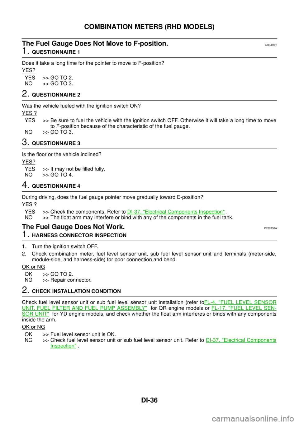
The Fuel Gauge Does Not Move to F-position.
EKS0030V
1.QUESTIONNAIRE 1
Does it take a long time for the pointer to move to F-position?
YES?
YES >> GO TO 2.
NO >> GO TO 3.
2.QUESTIONNAIRE 2
Was the vehicle fueled with the ignition switch ON?
YES ?
YES >> Be sure to fuel the vehicle with the ignition switch OFF. Otherwise it will take a long time to move
to F-position because of the characteristic of the fuel gauge.
NO >> GO TO 3.
3.QUESTIONNAIRE 3
Is the floor or the vehicle inclined?
YES?
YES >> It may not be filled fully.
NO >> GO TO 4.
4.QUESTIONNAIRE 4
During driving, does the fuel gauge pointer move gradually toward E-position?
YES ?
YES >> Check the components. Refer toDI-37, "Electrical Components Inspection".
NO >> The float arm may interfere or bind with any of the components in the fuel tank.
The Fuel Gauge Does Not Work.EKS0030W
1.HARNESS CONNECTOR INSPECTION
1. Turn the ignition switch OFF.
2. Check combination meter, fuel level sensor unit, sub fuel level sensor unit and terminals (meter-side,
module-side, and harness-side) for poor connection and bend.
OK or NG
OK >> GO TO 2.
NG >> Repair connector.
2.CHECK INSTALLATION CONDITION
Check fuel level sensor unit or sub fuel level sensor unit installation (refer toFL-4, "
FUEL LEVEL SENSOR
UNIT, FUEL FILTER AND FUEL PUMP ASSEMBLY"for QR engine models orFL-17, "FUEL LEVEL SEN-
SOR UNIT"for YD engine models, and check whether the float arm interferes or binds with any components
inside the arm.
OK or NG
OK >> Fuel level sensor unit is OK.
NG >> Check fuel level sensor unit or sub fuel level sensor unit. Refer toDI-37, "
Electrical Components
Inspection".
Page 1091 of 3066
COMBINATION METERS (RHD MODELS)
DI-37
C
D
E
F
G
H
I
J
L
MA
B
DI
Low Fuel Warning Lamp Illuminate or Not IlluminateEKS0030X
1.DIAGNOSIS MODE INSPECTION
Preform combination meter diagnosis mode. Refer toDI-28, "
Meter/Gauge Operation and Odo/Trip Meter
Segment Check in Diagnosis Mode".
OK or NG
OK >> Check fuel level sensor unit or sub fuel level sensor unit. Refer toDI-37, "Electrical Components
Inspection".
NG >> Replace combination meter.
Electrical Components InspectionEKS0031V
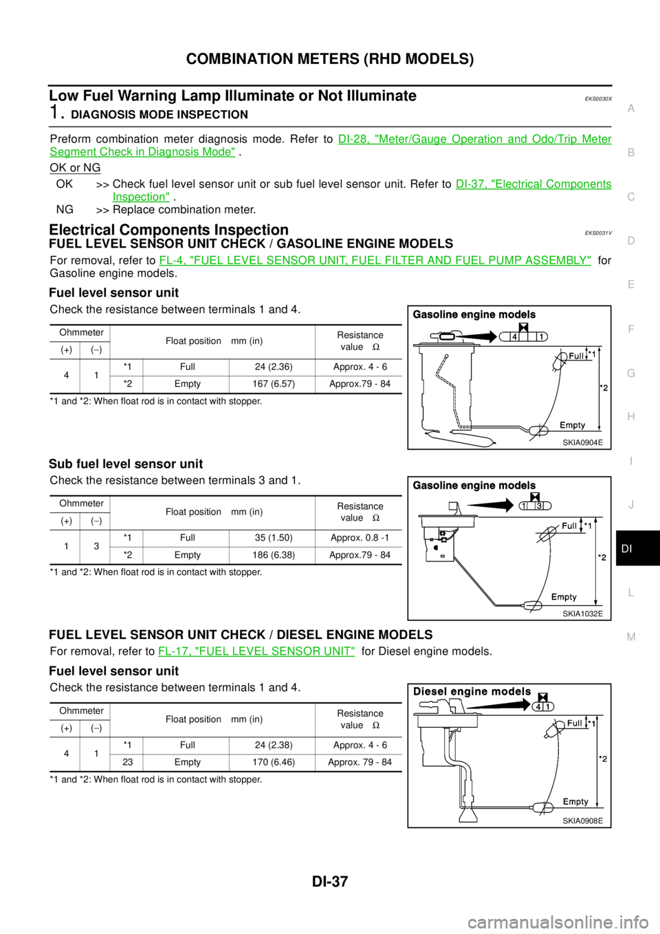
FUEL LEVEL SENSOR UNIT CHECK / GASOLINE ENGINE MODELS
For removal, refer toFL-4, "FUEL LEVEL SENSOR UNIT, FUEL FILTER AND FUEL PUMP ASSEMBLY"for
Gasoline engine models.
Fuel level sensor unit
Check the resistance between terminals 1 and 4.
*1 and *2: When float rod is in contact with stopper.
Sub fuel level sensor unit
Check the resistance between terminals 3 and 1.
*1 and *2: When float rod is in contact with stopper.
FUEL LEVEL SENSOR UNIT CHECK / DIESEL ENGINE MODELS
For removal, refer toFL-17, "FUEL LEVEL SENSOR UNIT"for Diesel engine models.
Fuel level sensor unit
Check the resistance between terminals 1 and 4.
*1 and *2: When float rod is in contact with stopper.Ohmmeter
Float position mm (in)Resistance
valueW
(+) (-)
41*1 Full 24 (2.36) Approx. 4 - 6
*2 Empty 167 (6.57) Approx.79 - 84
SKIA0904E
Ohmmeter
Float position mm (in)Resistance
valueW
(+) (-)
13*1 Full 35 (1.50) Approx. 0.8 -1
*2 Empty 186 (6.38) Approx.79 - 84
SKIA1032E
Ohmmeter
Float position mm (in)Resistance
valueW
(+) (-)
41*1 Full 24 (2.38) Approx. 4 - 6
23 Empty 170 (6.46) Approx. 79 - 84
SKIA0908E
Page 1092 of 3066
DI-38
COMBINATION METERS (RHD MODELS)
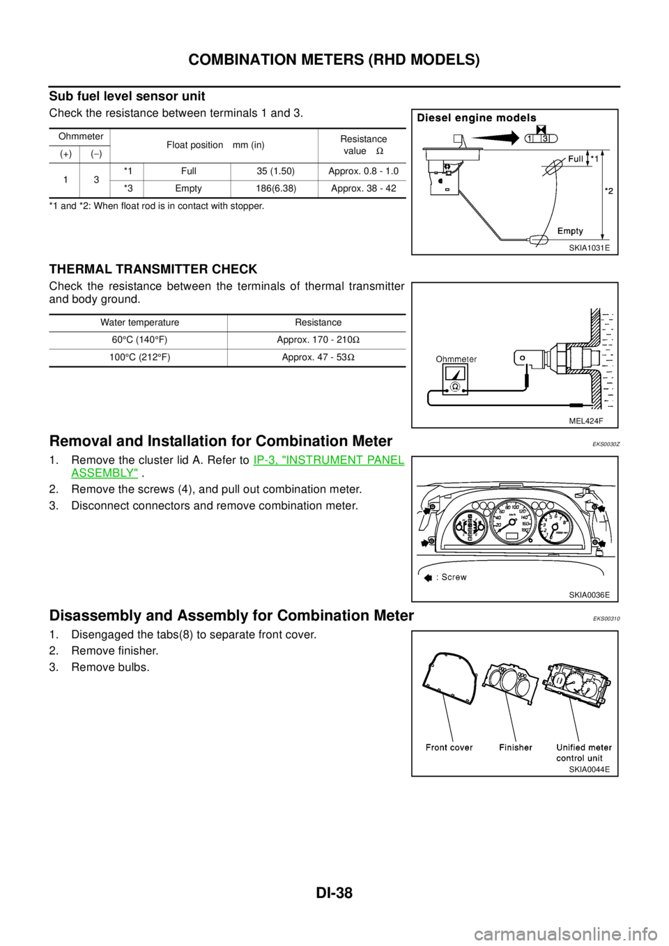
Sub fuel level sensor unit
Check the resistance between terminals 1 and 3.
*1 and *2: When float rod is in contact with stopper.
THERMAL TRANSMITTER CHECK
Check the resistance between the terminals of thermal transmitter
and body ground.
Removal and Installation for Combination MeterEKS0030Z
1. Remove the cluster lid A. Refer toIP-3, "INSTRUMENT PANEL
ASSEMBLY".
2. Remove the screws (4), and pull out combination meter.
3. Disconnect connectors and remove combination meter.
Disassembly and Assembly for Combination MeterEKS00310
1. Disengaged the tabs(8) to separate front cover.
2. Remove finisher.
3. Remove bulbs.
Ohmmeter
Float position mm (in)Resistance
valueW
(+) (-)
13*1 Full 35 (1.50) Approx. 0.8 - 1.0
*3 Empty 186(6.38) Approx. 38 - 42
SKIA1031E
Water temperature Resistance
60°C(140°F) Approx. 170 - 210W
100°C (212°F) Approx. 47 - 53W
MEL424F
SKIA0036E
SKIA0044E
Page 1104 of 3066
DI-50
WARNING LAMPS
Electrical Components Inspection
EKS002HK
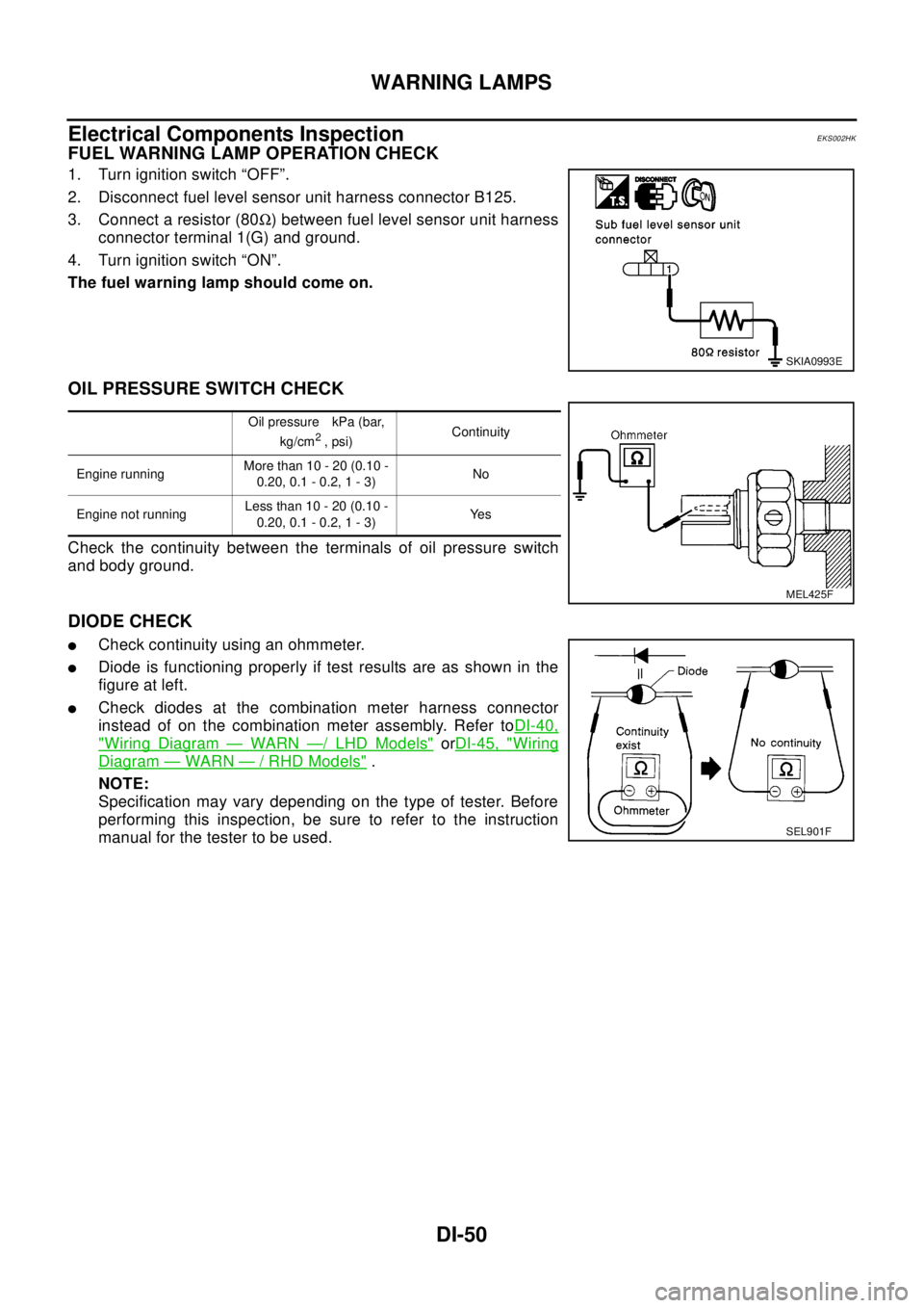
FUEL WARNING LAMP OPERATION CHECK
1. Turn ignition switch “OFF”.
2. Disconnect fuel level sensor unit harness connector B125.
3. Connect a resistor (80W) between fuel level sensor unit harness
connector terminal 1(G) and ground.
4. Turn ignition switch “ON”.
The fuel warning lamp should come on.
OIL PRESSURE SWITCH CHECK
Check the continuity between the terminals of oil pressure switch
and body ground.
DIODE CHECK
lCheck continuity using an ohmmeter.
lDiode is functioning properly if test results are as shown in the
figure at left.
lCheck diodes at the combination meter harness connector
instead of on the combination meter assembly. Refer toDI-40,
"Wiring Diagram—WARN—/LHDModels"orDI-45, "Wiring
Diagram—WARN—/RHDModels".
NOTE:
Specification may vary depending on the type of tester. Before
performing this inspection, be sure to refer to the instruction
manual for the tester to be used.
SKIA0993E
Oil pressure kPa (bar,
kg/cm2,psi)Continuity
Engine runningMore than 10 - 20 (0.10 -
0.20,0.1-0.2,1-3)No
Engine not runningLess than 10 - 20 (0.10 -
0.20,0.1-0.2,1-3)Ye s
MEL425F
SEL901F
Page 1106 of 3066

DI-52
WARNING CHIME
WARNING CHIME
PFP:24814
System DescriptionEKS002XF
POWER SUPPLY AND GROUND CIRCUIT
Power is supplied at all times
lthrough 10A fuse (No.31, located in fuse and fusible link box)
lto combination switch terminal 11,and
lto daytime light control unit terminal 1(with daytime light control unit).
lthrough 10A fuse [No.28, located in the fuse block (J/B)]
lto key switch terminal 1 and
lto time control unit terminal 1.
With ignition switch in ON or START position, power is supplied
lthrough 10A fuse [No.5, located in the fuse block (J/B)]
lto time control unit terminal 17.
Ground is supplied
lto time control unit terminal 16
lthrough body grounds M27 and M70.
When a signal, or combination of signals, is received by the time control unit, the warning chime will sound.
IGNITION KEY WARNING CHIME
With ignition switch in OFF or ACC position, and the driver's door open and driver’s door locked, the warning
chime will sound. Power is supplied
lthrough key switch terminal 2
lto time control unit terminal 18 and
Ground is supplied
lto time control unit terminal 28
lthrough unlock sensor terminal 5
Unlock sensor terminal 2 is grounded through body grounds M27 and M70, and
Ground is supplied
lto time control unit terminal 30
lthrough front door (driver side) switch terminal 2.
Front door switch (driver side) terminal 3 is grounded through body grounds B8 and B18.
LIGHT WARNING CHIME
With ignition switch OFF position, driver's door open, and lighting switch in 1ST or 2ND position, warning
chime will sound. Power is supplied
lfrom the lighting switch terminal 12 or daytime light control unit terminal 10 (with daytime light system)
lto time control unit terminal 19.
Ground is supplied
lfrom Front door switch (driver side) terminal 2
lto time control unit terminal 30.
Front door switch (driver side) terminal 3 is grounded through body grounds B8 and B18.
Page 1110 of 3066
DI-56
WARNING CHIME
Symptom Chart
EKS002XQ
Power Supply and Ground Circuit CheckEKS002YF
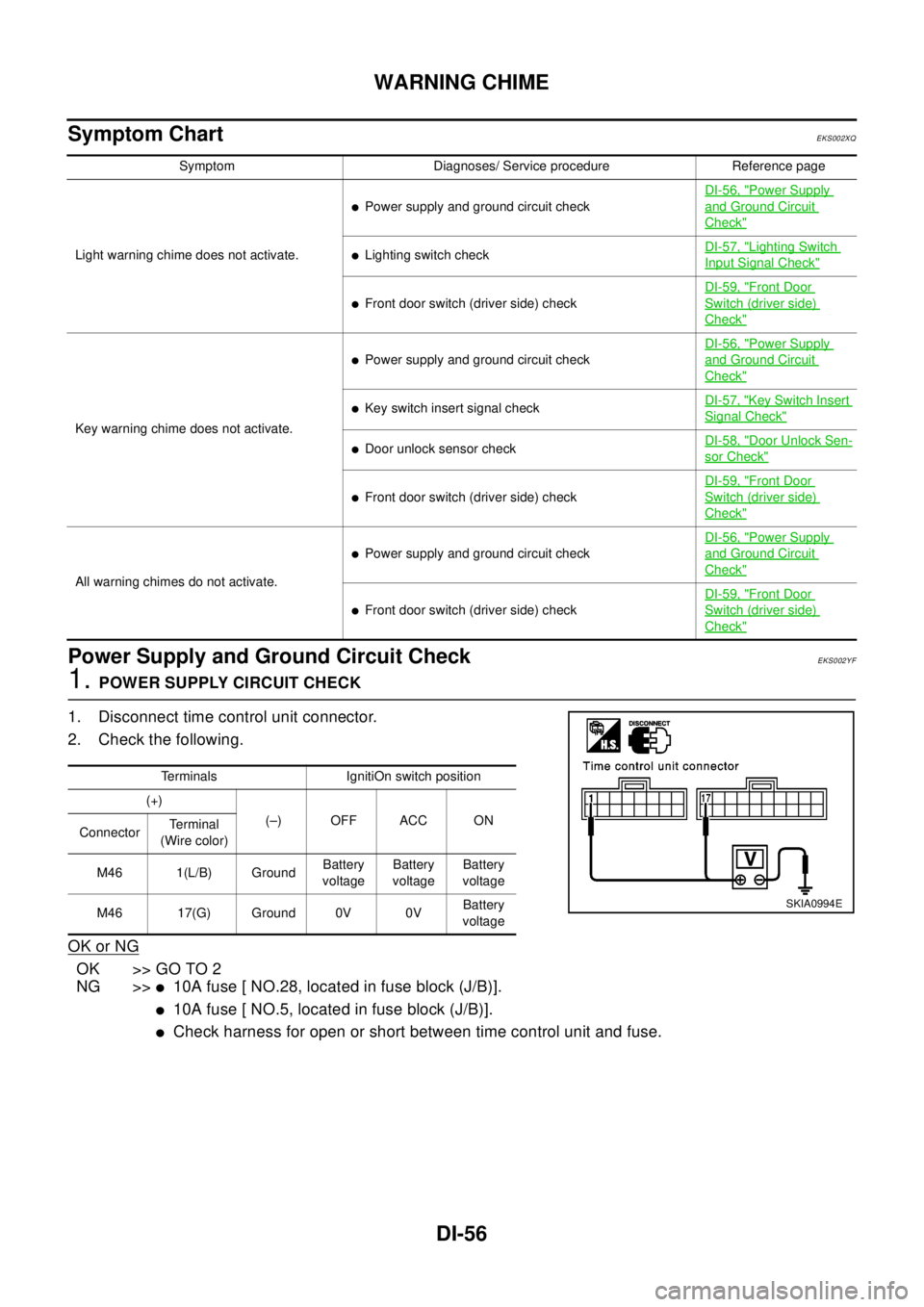
1.POWER SUPPLY CIRCUIT CHECK
1. Disconnect time control unit connector.
2. Check the following.
OK or NG
OK >> GO TO 2
NG >>
l10A fuse [ NO.28, located in fuse block (J/B)].
l10A fuse [ NO.5, located in fuse block (J/B)].
lCheck harness for open or short between time control unit and fuse.
Symptom Diagnoses/ Service procedure Reference page
Light warning chime does not activate.
lPower supply and ground circuit checkDI-56, "
Power Supply
and Ground Circuit
Check"
lLighting switch checkDI-57, "Lighting Switch
Input Signal Check"
lFront door switch (driver side) checkDI-59, "
Front Door
Switch (driver side)
Check"
Key warning chime does not activate.
lPower supply and ground circuit checkDI-56, "
Power Supply
and Ground Circuit
Check"
lKey switch insert signal checkDI-57, "Key Switch Insert
Signal Check"
lDoor unlock sensor checkDI-58, "Door Unlock Sen-
sor Check"
lFront door switch (driver side) checkDI-59, "
Front Door
Switch (driver side)
Check"
All warning chimes do not activate.
lPower supply and ground circuit checkDI-56, "
Power Supply
and Ground Circuit
Check"
lFront door switch (driver side) checkDI-59, "
Front Door
Switch (driver side)
Check"
Terminals IgnitiOn switch position
(+)
(–) OFF ACC ON
ConnectorTe r m i n a l
(Wire color)
M46 1(L/B) GroundBattery
voltageBattery
voltageBattery
voltage
M46 17(G) Ground 0V 0VBattery
voltage
SKIA0994E
Page 1112 of 3066
![NISSAN X-TRAIL 2003 Electronic Repair Manual DI-58
WARNING CHIME
2.CHECK KEY SWITCH (INSERT)
Check continuity between key switch connector M9 terminals 1 and
2.
OK or NG
OK >> Check the following.
l10A fuse [No. 28, located in fuse block (J/B)]
NISSAN X-TRAIL 2003 Electronic Repair Manual DI-58
WARNING CHIME
2.CHECK KEY SWITCH (INSERT)
Check continuity between key switch connector M9 terminals 1 and
2.
OK or NG
OK >> Check the following.
l10A fuse [No. 28, located in fuse block (J/B)]](/manual-img/5/57402/w960_57402-1111.png)
DI-58
WARNING CHIME
2.CHECK KEY SWITCH (INSERT)
Check continuity between key switch connector M9 terminals 1 and
2.
OK or NG
OK >> Check the following.
l10A fuse [No. 28, located in fuse block (J/B)]
lHarness for open or short between key switch and
fuse.
lHarness for open or short between time control unit and key switch.
NG >> Replace key switch.
Door Unlock Sensor CheckEKS002YG
1.CHECK DOOR UNLOCK SENSOR INPUT SIGNAL
Check voltage between time control unit harness connector M31 ter-
minal 28 (Y/G) and ground.
OK or NG
OK >> Door unlock sensor is OK.
NG >> GO TO 2.
2.CHECK DOOR UNLOCK SENSOR
1. Disconnect door unlock sensor connector.
2. Check continuity between door unlock sensor harness connec-
tor D9 terminals 2 and 5.
OK or NG
OK >> Check the following.
lDoor unlock sensor ground circuit.
lHarness for open or short between time control unit
and door unlock sensor.
NG >> Replace door unlock sensor.Condition of key switch Continuity
key switch inserted: Yes
key switch removed: No
SKIA0998E
Te r m i n a l s
Condition
(Driver's door)Voltage [V]
(+) (–)
28 GroundLocked Approx. 5
Unlocked 0
SKIA0999E
Condition of unlock sensor Continuity
Locked : No
Unlocked : Yes
SKIA1000E
Page 1115 of 3066
EC-1
ENGINE CONTROL SYSTEM
B ENGINE
CONTENTS
C
D
E
F
G
H
I
J
K
L
M
SECTION
A
EC
ENGINE CONTROL SYSTEM
QR (WITH EURO-OBD)
INDEX FOR DTC ...................................................... 12
Alphabetical Index .................................................. 12
DTC No. Index ....................................................... 14
PRECAUTIONS ........................................................ 16
Precautions for Supplemental Restraint System
(SRS) “AIR BAG” and “SEAT BELT PRE-TEN-
SIONER” ................................................................ 16
On Board Diagnostic (OBD) System of Engine and
A/T .......................................................................... 16
Precaution .............................................................. 16
Wiring Diagrams and Trouble Diagnosis ................ 19
PREPARATION ......................................................... 20
Special Service Tools ............................................. 20
Commercial Service Tools ...................................... 20
ENGINE CONTROL SYSTEM .................................. 22
System Diagram ..................................................... 22
Vacuum Hose Drawing ........................................... 23
System Chart ......................................................... 24
Multiport Fuel Injection (MFI) System .................... 24
Electronic Ignition (EI) System ............................... 27
Air Conditioning Cut Control ................................... 27
Fuel Cut Control (at No Load and High Engine
Speed) .................................................................... 28
CAN communication .............................................. 28
BASIC SERVICE PROCEDURE .............................. 30
Idle Speed and Ignition Timing Check .................... 30
Throttle Valve Closed Position Learning ................ 31
Accelerator Pedal Released Position Learning ...... 31
Idle Air Volume Learning ........................................ 31
Fuel Pressure Check .............................................. 34
ON BOARD DIAGNOSTIC (OBD) SYSTEM ............ 36
Introduction ............................................................ 36
Two Trip Detection Logic ........................................ 36
Emission-related Diagnostic Information ................ 37
NATS (Nissan Anti-theft System) ........................... 48
Malfunction Indicator (MI) ....................................... 48
OBD System Operation Chart ................................ 51
TROUBLE DIAGNOSIS ............................................ 57
Trouble Diagnosis Introduction ............................... 57DTC Inspection Priority Chart ................................. 61
Fail-safe Chart ........................................................ 62
Basic Inspection ..................................................... 64
Symptom Matrix Chart ............................................ 69
Engine Control Component Parts Location ............ 73
Circuit Diagram ....................................................... 77
ECM Harness Connector Terminal Layout ............. 79
ECM Terminals and Reference Value ..................... 79
CONSULT-II Function ............................................. 86
Generic Scan Tool (GST) Function ......................... 96
CONSULT-II Reference Value in Data Monitor ....... 97
Major Sensor Reference Graph in Data Monitor
Mode .....................................................................100
TROUBLE DIAGNOSIS - SPECIFICATION VALUE. 103
Description ............................................................103
Testing Condition ..................................................103
Inspection Procedure ............................................103
Diagnostic Procedure ...........................................104
TROUBLE DIAGNOSIS FOR INTERMITTENT INCI-
DENT .......................................................................107
Description ............................................................107
Diagnostic Procedure ...........................................107
POWER SUPPLY CIRCUIT FOR ECM ...................108
Wiring Diagram .....................................................108
ECM Terminals and Reference Value ...................109
Diagnostic Procedure ...........................................109
Component Inspection ..........................................113
DTC U1000 CAN COMMUNICATION LINE ............114
Description ............................................................114
On Board Diagnosis Logic ....................................114
DTC Confirmation Procedure ...............................114
Wiring Diagram .....................................................115
Diagnostic Procedure ...........................................116
DTC P0011 IVT CONTROL .....................................117
Description ............................................................117
CONSULT-II Reference Value in Data Monitor Mode
.117
ECM Terminals and Reference Value ...................117
On Board Diagnosis Logic ....................................118