Page 667 of 3066
TROUBLE DIAGNOSIS
ATC-89
C
D
E
F
G
H
I
K
L
MA
B
AT C
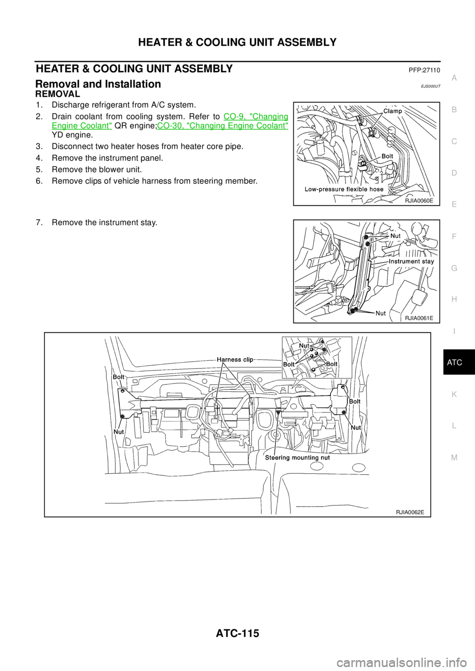
Low-pressure Side Becomes Negative.
Insufficient HeatingEJS001H7
SYMPTOM: Insufficient heating
Gauge indication Refrigerant cycle Probable cause Corrective action
Low-pressure side becomes nega-
tive.
Liquid tank or front/rear side of
expansion valve's pipe is
frosted or dewed.High-pressure side is closed
and refrigerant does not flow.
¯
Expansion valve or liquid tank
is frosted.Leave the system at rest until
no frost is present. Start it
again to check whether or not
the problem is caused by
water or foreign particles.
lIf water is the cause, initially
cooling is okay. Then the
water freezes causing a
blockage. Drain water from
refrigerant or replace refrig-
erant.
lIf due to foreign particles,
remove expansion valve
and remove the particles
with dry and compressed air
(not shop air).
lIf either of the above meth-
ods cannot correct the prob-
lem, replace expansion
valve.
lReplace desiccant assy.
lCheck lubricant for contami-
nation.
AC362A
Page 674 of 3066
ATC-96
TROUBLE DIAGNOSIS
Aspirator
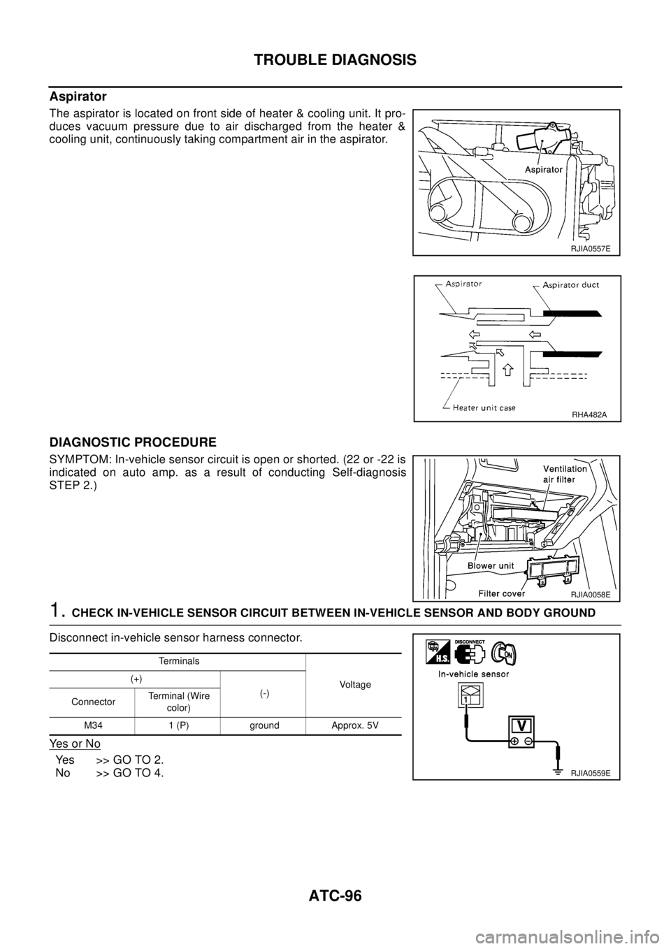
The aspirator is located on front side of heater & cooling unit. It pro-
duces vacuum pressure due to air discharged from the heater &
cooling unit, continuously taking compartment air in the aspirator.
DIAGNOSTIC PROCEDURE
SYMPTOM: In-vehicle sensor circuit is open or shorted. (22 or -22 is
indicated on auto amp. as a result of conducting Self-diagnosis
STEP 2.)
1.CHECK IN-VEHICLE SENSOR CIRCUIT BETWEEN IN-VEHICLE SENSOR AND BODY GROUND
Disconnect in-vehicle sensor harness connector.
Ye s o r N o
Yes >>GOTO2.
No >> GO TO 4.
RJIA0557E
RHA482A
RJIA0058E
Te r m i n a l s
Voltag e (+)
(-)
ConnectorTerminal (Wire
color)
M34 1 (P) ground Approx. 5V
RJIA0559E
Page 679 of 3066
TROUBLE DIAGNOSIS
ATC-101
C
D
E
F
G
H
I
K
L
MA
B
AT C
Intake Sensor CircuitEJS001HE
COMPONENT DESCRIPTION
Intake Sensor
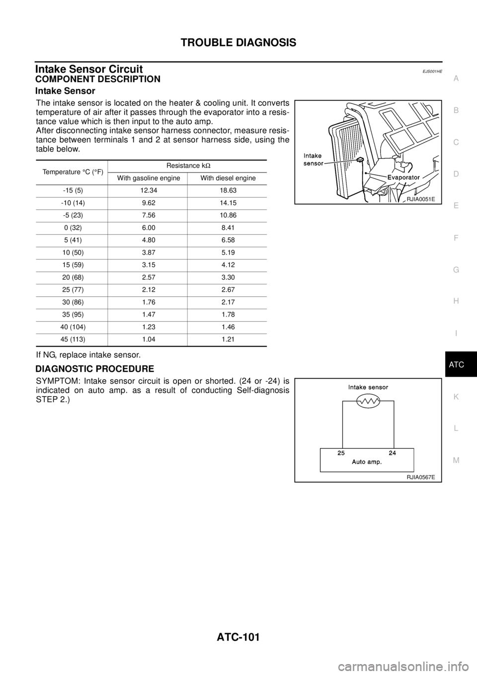
The intake sensor is located on the heater & cooling unit. It converts
temperature of air after it passes through the evaporator into a resis-
tance value which is then input to the auto amp.
After disconnecting intake sensor harness connector, measure resis-
tance between terminals 1 and 2 at sensor harness side, using the
table below.
If NG, replace intake sensor.
DIAGNOSTIC PROCEDURE
SYMPTOM: Intake sensor circuit is open or shorted. (24 or -24) is
indicated on auto amp. as a result of conducting Self-diagnosis
STEP 2.)
Temperature°C(°F)Resistance kW
With gasoline engine With diesel engine
-15 (5) 12.34 18.63
-10 (14) 9.62 14.15
-5 (23) 7.56 10.86
0(32) 6.00 8.41
5(41) 4.80 6.58
10 (50) 3.87 5.19
15 (59) 3.15 4.12
20 (68) 2.57 3.30
25 (77) 2.12 2.67
30 (86) 1.76 2.17
35 (95) 1.47 1.78
40 (104) 1.23 1.46
45 (113) 1.04 1.21
RJIA0051E
RJIA0567E
Page 688 of 3066
ATC-110
BLOWER UNIT
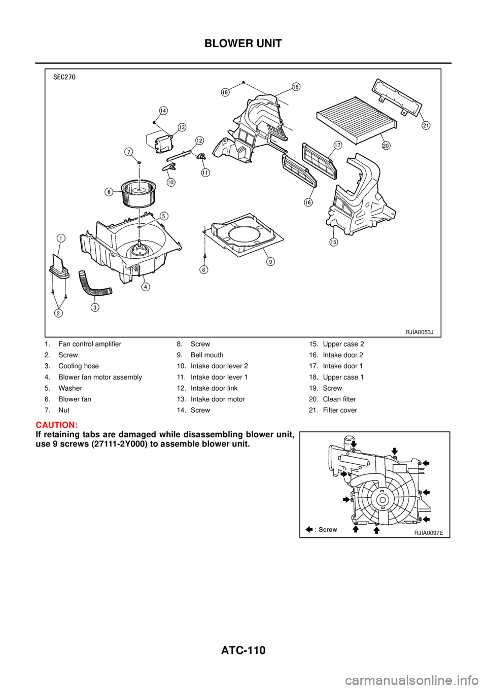
CAUTION:
If retaining tabs are damaged while disassembling blower unit,
use 9 screws (27111-2Y000) to assemble blower unit.
1. Fan control amplifier 8. Screw 15. Upper case 2
2. Screw 9. Bell mouth 16. Intake door 2
3. Cooling hose 10. Intake door lever 2 17. Intake door 1
4. Blower fan motor assembly 11. Intake door lever 1 18. Upper case 1
5. Washer 12. Intake door link 19. Screw
6. Blower fan 13. Intake door motor 20. Clean filter
7. Nut 14. Screw 21. Filter cover
RJIA0053J
RJIA0097E
Page 689 of 3066
BLOWER MOTOR
ATC-111
C
D
E
F
G
H
I
K
L
MA
B
AT C
BLOWER MOTORPFP:27226
Removal and InstallationEJS000UN
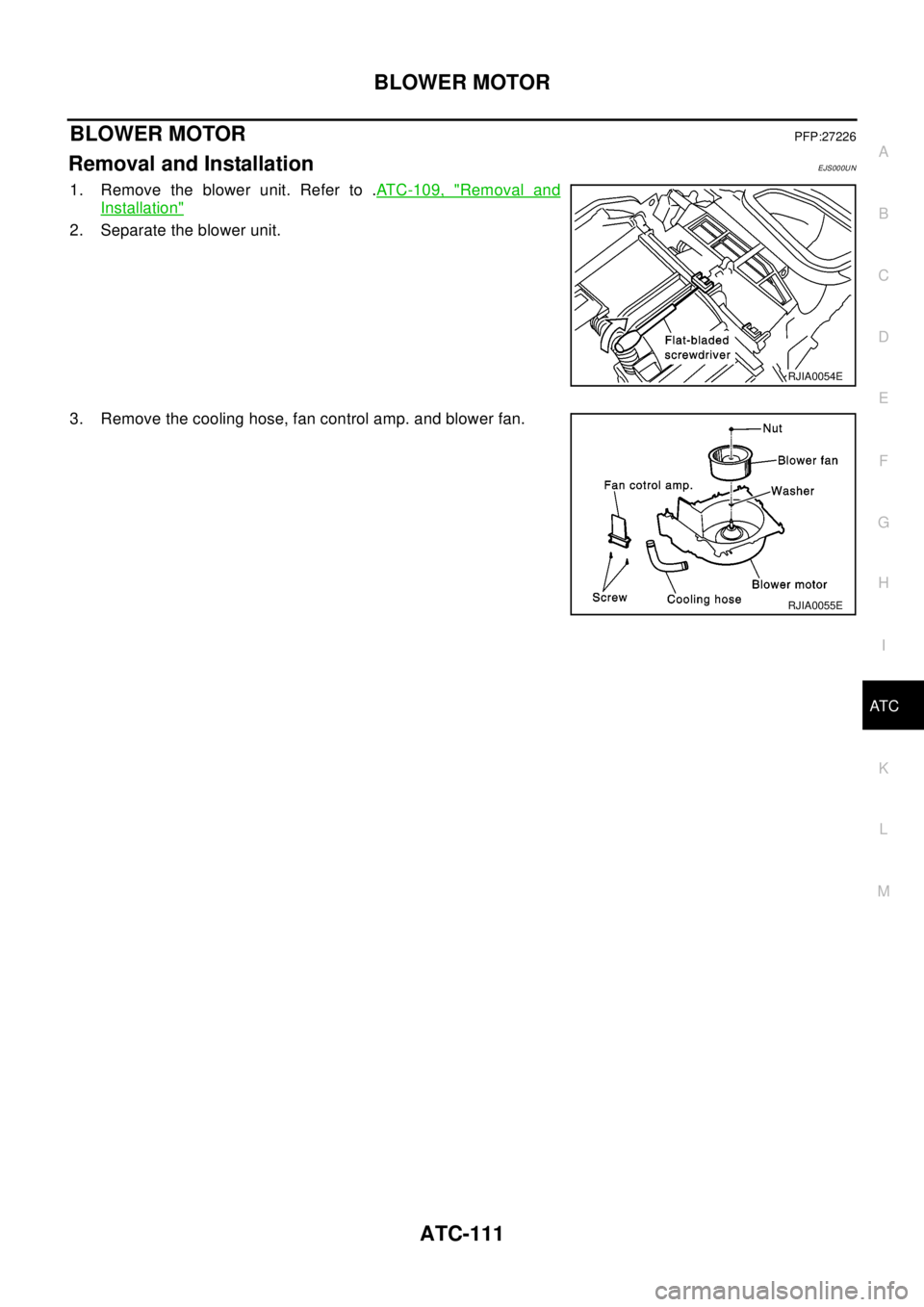
1. Remove the blower unit. Refer to .ATC-109, "Removal and
Installation"
2. Separate the blower unit.
3. Remove the cooling hose, fan control amp. and blower fan.
RJIA0054E
RJIA0055E
Page 693 of 3066
HEATER & COOLING UNIT ASSEMBLY
ATC-115
C
D
E
F
G
H
I
K
L
MA
B
AT C
HEATER & COOLING UNIT ASSEMBLYPFP:27110
Removal and InstallationEJS000UT
REMOVAL
1. Discharge refrigerant from A/C system.
2. Drain coolant from cooling system. Refer toCO-9, "
Changing
Engine Coolant"QR engine;CO-30, "Changing Engine Coolant"
YD engine.
3. Disconnect two heater hoses from heater core pipe.
4. Remove the instrument panel.
5. Remove the blower unit.
6. Remove clips of vehicle harness from steering member.
7. Remove the instrument stay.
RJIA0060E
RJIA0061E
RJIA0062E
Page 694 of 3066
ATC-116
HEATER & COOLING UNIT ASSEMBLY
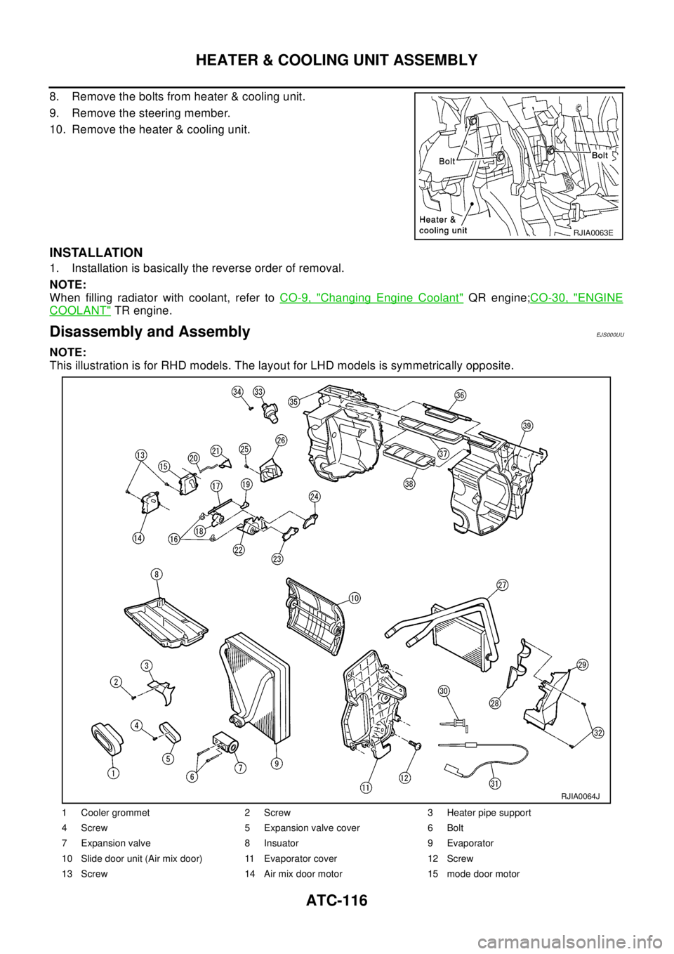
8. Remove the bolts from heater & cooling unit.
9. Remove the steering member.
10. Remove the heater & cooling unit.
INSTALLATION
1. Installation is basically the reverse order of removal.
NOTE:
When filling radiator with coolant, refer toCO-9, "
Changing Engine Coolant"QR engine;CO-30, "ENGINE
COOLANT"TR engine.
Disassembly and AssemblyEJ S00 0UU
NOTE:
This illustration is for RHD models. The layout for LHD models is symmetrically opposite.
RJIA0063E
1 Cooler grommet 2 Screw 3 Heater pipe support
4 Screw 5 Expansion valve cover 6 Bolt
7 Expansion valve 8 Insuator 9 Evaporator
10 Slide door unit (Air mix door) 11 Evaporator cover 12 Screw
13 Screw 14 Air mix door motor 15 mode door motor
RJIA0064J
Page 695 of 3066
HEATER & COOLING UNIT ASSEMBLY
ATC-117
C
D
E
F
G
H
I
K
L
MA
B
AT C
16 Screw 17 Ventilator door link 1 18 Ventilator door link 2
19 Ventilator door lever 20 Rod 21 Rod holder
22 Main link 23 Max cool door lever 24 Defroster door lever
25 Screw 26 Foot duct (right side) 27 Heater core
28 Heater core cover 29 Foot duct (left side) 30 Intake sensor bracket
31 Intake sensor 32 Screw 33 Aspirator
34 Screw 35 Heater & cooling unit case (right side) 36 Defroster door
37 Ventilator door 38 Max cool door 39 Heater & cooling unit case (left side)