Page 2666 of 3066
MTC-30
DUCTS AND GRILLES
Foot Duct
EJS000Y0
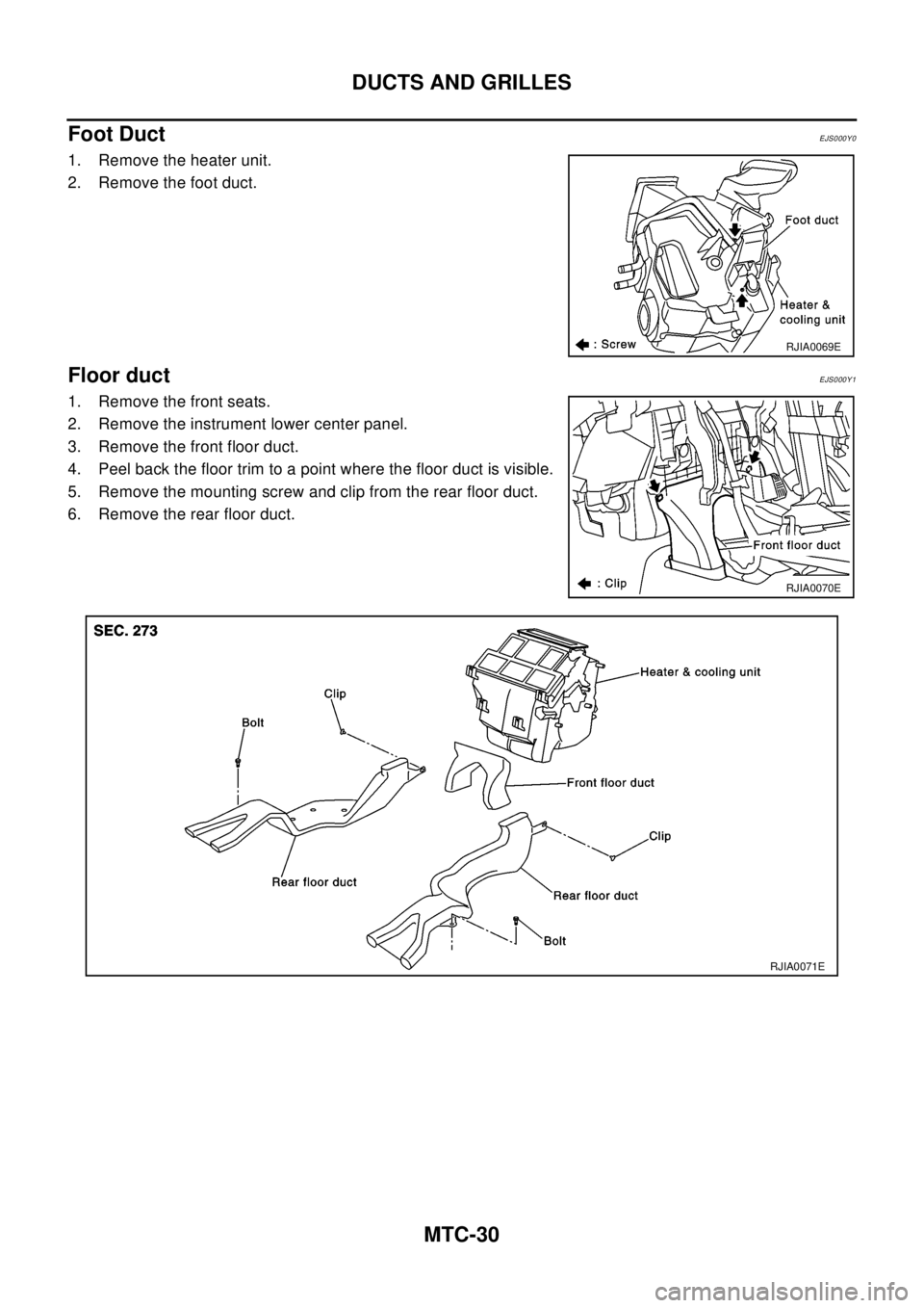
1. Remove the heater unit.
2. Remove the foot duct.
Floor ductEJS000Y1
1. Remove the front seats.
2. Remove the instrument lower center panel.
3. Remove the front floor duct.
4. Peel back the floor trim to a point where the floor duct is visible.
5. Remove the mounting screw and clip from the rear floor duct.
6. Remove the rear floor duct.
RJIA0069E
RJIA0070E
RJIA0071E
Page 2820 of 3066
RF-8
SUNROOF
SUNROOF UNIT
Removal
CAUTION:
lRemoval and installation of sunroof unit require 2 workers.
lWhen taking sunroof unit out, use shop cloths to protect seats and trim from damage.
lAfter installing sunroof unit and glass lid, be sure to carry out the leak test to confirm there is no
more leakage.
1. Remove headlining. Refer toEI-29, "
HEADLINING"
2. Disconnect drain hoses (4).
3. Disconnect interior lamp harness.
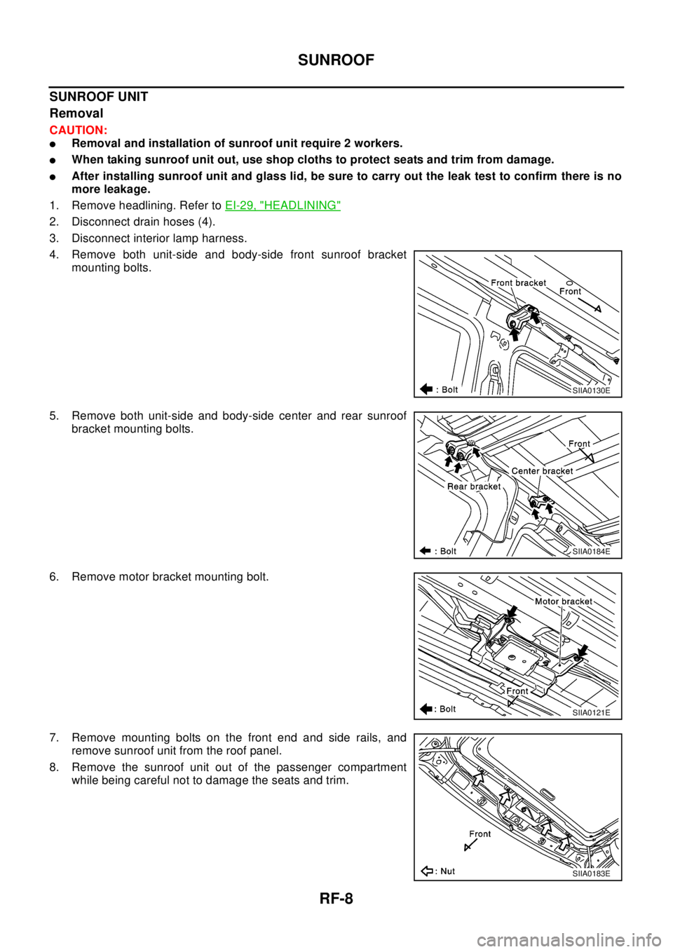
4. Remove both unit-side and body-side front sunroof bracket
mounting bolts.
5. Remove both unit-side and body-side center and rear sunroof
bracket mounting bolts.
6. Remove motor bracket mounting bolt.
7. Remove mounting bolts on the front end and side rails, and
remove sunroof unit from the roof panel.
8. Remove the sunroof unit out of the passenger compartment
while being careful not to damage the seats and trim.
SIIA0130E
SIIA0184E
SIIA0121E
SIIA0183E
Page 2860 of 3066
RSU-8
COIL SPRING AND STRUT
COIL SPRING AND STRUT
PFP:55302
Removal and InstallationEES0007H
REMOVAL
1. Remove tires.
2. Remove brake hose lock plate and remove brake hose from strut.
3. Remove mounting nuts and washers on upper portion of stabilizer connecting rod.
4. Remove strut-to-axle housing mounting bolts and nuts.
5. Remove luggage side lower finisher in luggage compartment.Remove mounting nuts on upper portion of
strut. Then remove strut from vehicle.
INSTALLATION
lRefer toRSU-5, "Components"for tightening torque. Install in the reverse order of removal.
Disassembly and AssemblyEES0007I
DISASSEMBLY
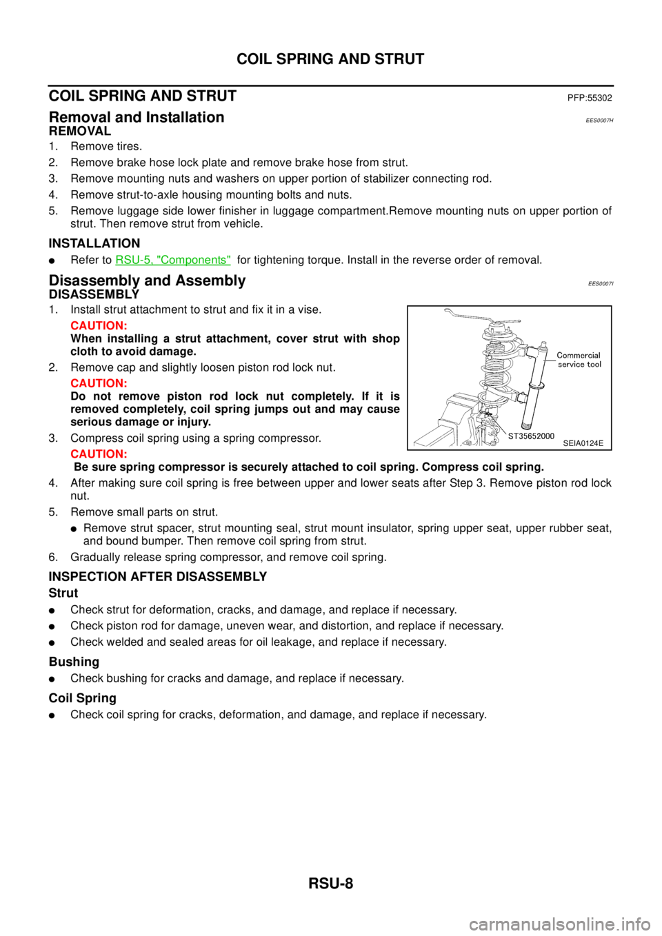
1. Install strut attachment to strut and fix it in a vise.
CAUTION:
When installing a strut attachment, cover strut with shop
cloth to avoid damage.
2. Remove cap and slightly loosen piston rod lock nut.
CAUTION:
Do not remove piston rod lock nut completely. If it is
removed completely, coil spring jumps out and may cause
serious damage or injury.
3. Compress coil spring using a spring compressor.
CAUTION:
Be sure spring compressor is securely attached to coil spring. Compress coil spring.
4. After making sure coil spring is free between upper and lower seats after Step 3. Remove piston rod lock
nut.
5. Remove small parts on strut.
lRemove strut spacer, strut mounting seal, strut mount insulator, spring upper seat, upper rubber seat,
and bound bumper. Then remove coil spring from strut.
6. Gradually release spring compressor, and remove coil spring.
INSPECTION AFTER DISASSEMBLY
Strut
lCheck strut for deformation, cracks, and damage, and replace if necessary.
lCheck piston rod for damage, uneven wear, and distortion, and replace if necessary.
lCheck welded and sealed areas for oil leakage, and replace if necessary.
Bushing
lCheck bushing for cracks and damage, and replace if necessary.
Coil Spring
lCheck coil spring for cracks, deformation, and damage, and replace if necessary.
SEIA0124E
Page 2861 of 3066
COIL SPRING AND STRUT
RSU-9
C
D
F
G
H
I
J
K
L
MA
B
RSU
ASSEMBLY
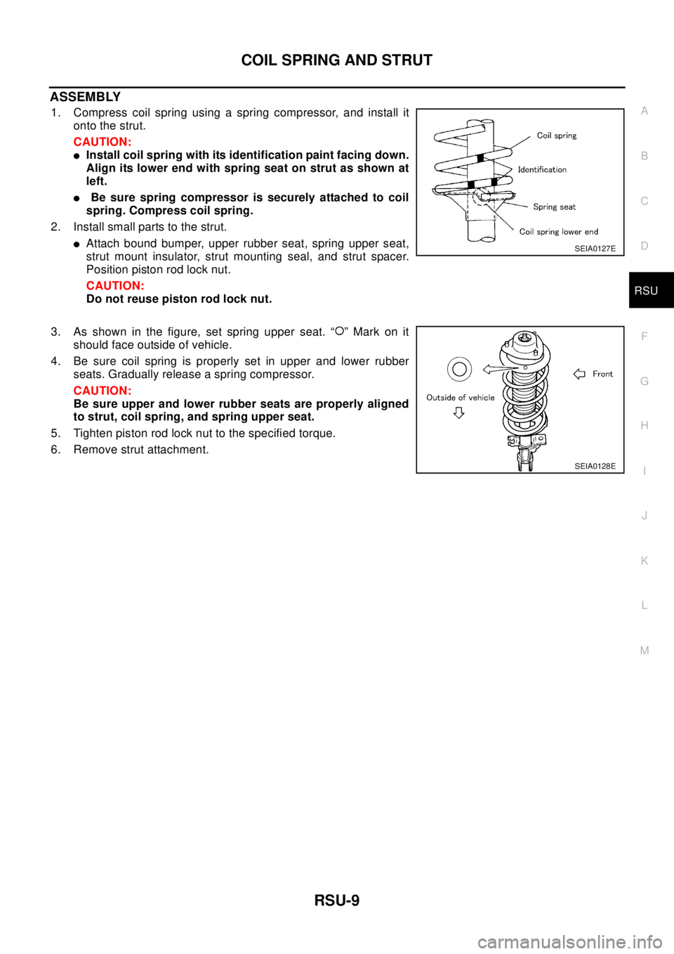
1. Compress coil spring using a spring compressor, and install it
onto the strut.
CAUTION:
lInstall coil spring with its identification paint facing down.
Align its lower end with spring seat on strut as shown at
left.
lBe sure spring compressor is securely attached to coil
spring. Compress coil spring.
2. Install small parts to the strut.
lAttach bound bumper, upper rubber seat, spring upper seat,
strut mount insulator, strut mounting seal, and strut spacer.
Position piston rod lock nut.
CAUTION:
Do not reuse piston rod lock nut.
3. As shown in the figure, set spring upper seat. “ ” Mark on it
should face outside of vehicle.
4. Be sure coil spring is properly set in upper and lower rubber
seats. Gradually release a spring compressor.
CAUTION:
Be sure upper and lower rubber seats are properly aligned
to strut, coil spring, and spring upper seat.
5. Tighten piston rod lock nut to the specified torque.
6. Remove strut attachment.SEIA0127E
SEIA0128E
Page 2997 of 3066
TRANSFER ASSEMBLY
TF-27
C
E
F
G
H
I
J
K
L
MA
B
TF
Drive gear assembly
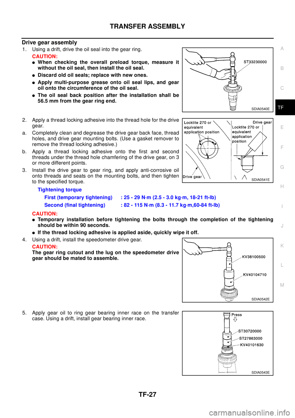
1. Using a drift, drive the oil seal into the gear ring.
CAUTION:
lWhen checking the overall preload torque, measure it
without the oil seal, then install the oil seal.
lDiscard old oil seals; replace with new ones.
lApply multi-purpose grease onto oil seal lips, and gear
oil onto the circumference of the oil seal.
lThe oil seal back position after the installation shall be
56.5 mm from the gear ring end.
2. Apply a thread locking adhesive into the thread hole for the drive
gear.
a. Completely clean and degrease the drive gear back face, thread
holes, and drive gear mounting bolts. (Use a gasket remover to
remove the thread locking adhesive.)
b. Apply a thread locking adhesive onto the first and second
threads under the thread hole chamfering of the drive gear, on 3
or more different points.
3. Install the drive gear to gear ring, and apply anti-corrosive oil
onto threads and seats on the mounting bolts, and then tighten
to the specified torque.
CAUTION:
lTemporary installation before tightening the bolts through the completion of the tightening
should be within 90 seconds.
lIf the thread locking adhesive is applied aside, quickly wipe it off.
4. Using a drift, install the speedometer drive gear.
CAUTION:
The gear ring cutout and the lug on the speedometer drive
gear should be mated to assemble.
5. Apply gear oil to ring gear bearing inner race on the transfer
case. Using a drift, install gear bearing inner race.
SDIA0540E
Tightening torque
First (temporary tightening) : 25 - 29 N·m (2.5 - 3.0 kg·m, 18-21 ft-lb)
Second (final tightening) : 82 - 115 N·m (8.3 - 11.7 kg·m,60-84 ft-lb)
SDIA0541E
SDIA0542E
SDIA0543E