2003 NISSAN X-TRAIL check transmission fluid
[x] Cancel search: check transmission fluidPage 993 of 3066

CL-1
CLUTCH
C TRANSMISSION/TRANSAXLE
CONTENTS
D
E
F
G
H
I
J
K
L
M
SECTION
A
B
CL
CLUTCH
PRECAUTIONS .......................................................... 2
Caution ..................................................................... 2
PREPARATION ........................................................... 3
Special Service Tools ............................................... 3
Commercial Service Tool ......................................... 3
NOISE, VIBRATION, AND HARSHNESS (NVH)
TROUBLESHOOTING ................................................ 4
NVH Troubleshooting Chart ..................................... 4
CLUTCH PEDAL ........................................................ 5
On-vehicle Inspection and Adjustment ..................... 5
HEIGHT ADJUSTMENT ....................................... 5
CLUTCH SWITCH POSITION ADJUSTMENT ..... 5
FREE PLAY INSPECTION .................................... 6
CLEARANCE CHECK ........................................... 6
Removal and Installation .......................................... 6
INSPECTION AFTER REMOVAL ......................... 7
CLUTCH FLUID .......................................................... 8
Air Bleeding Procedure ............................................ 8
CLUTCH MASTER CYLINDER .................................. 9
Removal and Installation .......................................... 9
REMOVAL ............................................................. 9
INSTALLATION ..................................................... 9
Disassembly and Assembly ................................... 10
DISASSEMBLY ................................................... 10
INSPECTION AFTER DISASSEMBLY ............... 10
ASSEMBLY ......................................................... 10
OPERATING CYLINDER ...........................................11Removal and Installation ........................................ 11
REMOVAL ........................................................... 11
INSTALLATION ................................................... 11
Disassembly and Assembly .................................... 11
DISASSEMBLY ................................................... 11
INSPECTION AFTER DISASSEMBLY ................ 11
ASSEMBLY ......................................................... 11
CLUTCH PIPING ....................................................... 12
Removal and Installation ........................................ 12
CLUTCH RELEASE MECHANISM ........................... 13
Removal and Installation ........................................ 13
REMOVAL ........................................................... 13
INSPECTION AFTER REMOVEL ....................... 13
INSTALLATION ................................................... 13
CLUTCH DISC, CLUTCH COVER AND FLYWHEEL... 15
Removal and Installation ........................................ 15
REMOBAL ........................................................... 15
INSPECTION AND ADJUSTMENT AFTER
REMOVAL ........................................................... 15
INSTALLATION ................................................... 16
SERVICE DATA AND SPECIFICATIONS (SDS) ...... 17
Clutch Control System ............................................ 17
Clutch Master Cylinder ........................................... 17
Clutch Operating Cylinder ...................................... 17
Clutch Disk ............................................................. 17
Clutch Cover ........................................................... 17
Clutch Pedal ........................................................... 17
Page 1146 of 3066
![NISSAN X-TRAIL 2003 Electronic Repair Manual EC-32
[QR (WITH EURO-OBD)]
BASIC SERVICE PROCEDURE
PREPARATION
Before performing “Idle Air Volume Learning”, make sure that all of the following conditions are satisfied.
Learning will be cancelle NISSAN X-TRAIL 2003 Electronic Repair Manual EC-32
[QR (WITH EURO-OBD)]
BASIC SERVICE PROCEDURE
PREPARATION
Before performing “Idle Air Volume Learning”, make sure that all of the following conditions are satisfied.
Learning will be cancelle](/manual-img/5/57402/w960_57402-1145.png)
EC-32
[QR (WITH EURO-OBD)]
BASIC SERVICE PROCEDURE
PREPARATION
Before performing “Idle Air Volume Learning”, make sure that all of the following conditions are satisfied.
Learning will be cancelled if any of the following conditions are missed for even a moment.
lBattery voltage: More than 12.9V (At idle)
lEngine coolant temperature: 70 - 100°C (158 - 212°F)
lPNP switch: ON
lElectric load switch: OFF
(Air conditioner, headlamp, rear window defogger)
On vehicles equipped with daytime light systems, set lighting switch to the 1st position to light
only small lamps.
lSteering wheel: Neutral (Straight-ahead position)
lVehicle speed: Stopped
lTransmission: Warmed-up
For A/T models with CONSULT-II, drive vehicle until “FLUID TEMP SE” in “DATA MONITOR” mode of “A/
T” system indicates less than 0.9V.
For A/T models without CONSULT-II and M/T models, drive vehicle for 10 minutes.
OPERATION PROCEDURE
With CONSULT-II
1. PerformEC-31, "Accelerator Pedal Released Position Learning".
2. PerformEC-31, "
Throttle Valve Closed Position Learning".
3. Start engine and warm it up to normal operating temperature.
4. Check that all items listed under the topic “PRE-CONDITIONING” (previously mentioned) are in good
order.
5. Select “IDLE AIR VOL LEARN” in “WORK SUPPORT” mode.
6. Touch “START” and wait 20 seconds.
SEF452Y
SEF454Y
Page 1511 of 3066
![NISSAN X-TRAIL 2003 Electronic Repair Manual BASIC SERVICE PROCEDURE
EC-397
[QR (WITHOUT EURO-OBD)]
C
D
E
F
G
H
I
J
K
L
MA
EC
PREPARATION
Before performing “Idle Air Volume Learning”, make sure that all of the following conditions are satisf NISSAN X-TRAIL 2003 Electronic Repair Manual BASIC SERVICE PROCEDURE
EC-397
[QR (WITHOUT EURO-OBD)]
C
D
E
F
G
H
I
J
K
L
MA
EC
PREPARATION
Before performing “Idle Air Volume Learning”, make sure that all of the following conditions are satisf](/manual-img/5/57402/w960_57402-1510.png)
BASIC SERVICE PROCEDURE
EC-397
[QR (WITHOUT EURO-OBD)]
C
D
E
F
G
H
I
J
K
L
MA
EC
PREPARATION
Before performing “Idle Air Volume Learning”, make sure that all of the following conditions are satisfied.
Learning will be cancelled if any of the following conditions are missed for even a moment.
lBattery voltage: More than 12.9V (At idle)
lEngine coolant temperature: 70 - 100°C (158 - 212°F)
lPNP switch: ON
lElectric load switch: OFF
(Air conditioner, headlamp, rear window defogger)
On vehicles equipped with daytime light systems, set lighting switch to the 1st position to light
only small lamps.
lSteering wheel: Neutral (Straight-ahead position)
lVehicle speed: Stopped
lTransmission: Warmed-up
For A/T models with CONSULT-II, drive vehicle until “FLUID TEMP SE” in “DATA MONITOR” mode of “A/
T” system indicates less than 0.9V.
For A/T models without CONSULT-II and M/T models, drive vehicle for 10 minutes.
OPERATION PROCEDURE
With CONSULT-II
1. PerformEC-396, "Accelerator Pedal Released Position Learning".
2. PerformEC-396, "
Throttle Valve Closed Position Learning".
3. Start engine and warm it up to normal operating temperature.
4. Check that all items listed under the topic “PRE-CONDITIONING” (previously mentioned) are in good
order.
5. Select “IDLE AIR VOL LEARN” in “WORK SUPPORT” mode.
6. Touch “START” and wait 20 seconds.
SEF452Y
SEF454Y
Page 2258 of 3066

PRECAUTIONS
GI-5
lUse only the fluids and lubricants specified in this manual.
lUse approved bonding agent, sealants or their equivalents when required.
lUse tools and recommended special tools where specified for safe and efficient service repairs.
lWhen repairing the fuel, oil, water, vacuum or exhaust systems, check all affected lines for leaks.
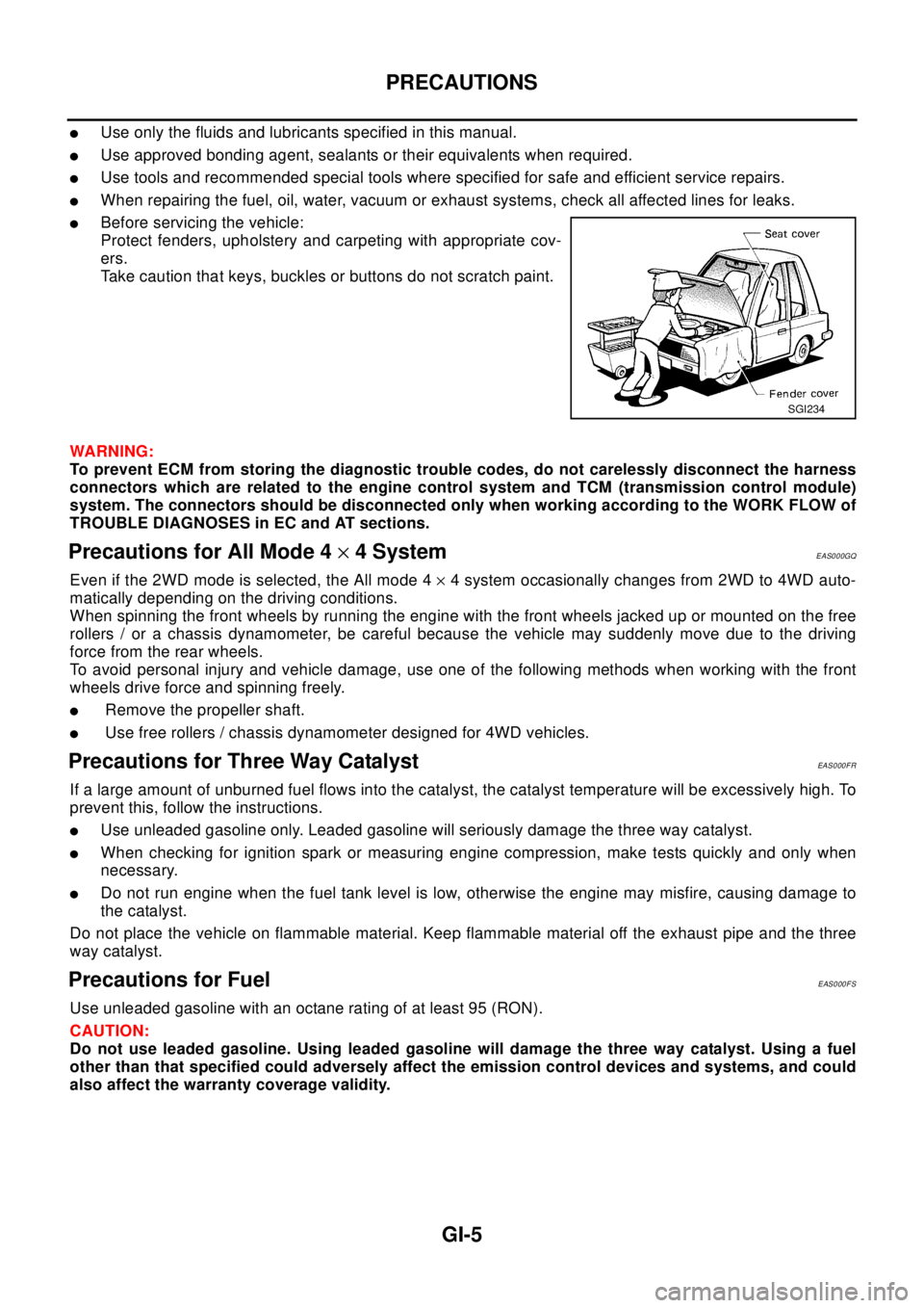
lBefore servicing the vehicle:
Protect fenders, upholstery and carpeting with appropriate cov-
ers.
Take caution that keys, buckles or buttons do not scratch paint.
WA RN ING:
To prevent ECM from storing the diagnostic trouble codes, do not carelessly disconnect the harness
connectors which are related to the engine control system and TCM (transmission control module)
system. The connectors should be disconnected only when working according to the WORK FLOW of
TROUBLE DIAGNOSES in EC and AT sections.
Precautions for All Mode 4´4 SystemEAS000GQ
Even if the 2WD mode is selected, the All mode 4´4 system occasionally changes from 2WD to 4WD auto-
matically depending on the driving conditions.
When spinning the front wheels by running the engine with the front wheels jacked up or mounted on the free
rollers / or a chassis dynamometer, be careful because the vehicle may suddenly move due to the driving
force from the rear wheels.
To avoid personal injury and vehicle damage, use one of the following methods when working with the front
wheels drive force and spinning freely.
lRemove the propeller shaft.
lUse free rollers / chassis dynamometer designed for 4WD vehicles.
Precautions for Three Way CatalystEAS000FR
If a large amount of unburned fuel flows into the catalyst, the catalyst temperature will be excessively high. To
prevent this, follow the instructions.
lUse unleaded gasoline only. Leaded gasoline will seriously damage the three way catalyst.
lWhen checking for ignition spark or measuring engine compression, make tests quickly and only when
necessary.
lDo not run engine when the fuel tank level is low, otherwise the engine may misfire, causing damage to
the catalyst.
Do not place the vehicle on flammable material. Keep flammable material off the exhaust pipe and the three
way catalyst.
Precautions for FuelEAS000FS
Use unleaded gasoline with an octane rating of at least 95 (RON).
CAUTION:
Do not use leaded gasoline. Using leaded gasoline will damage the three way catalyst. Using a fuel
other than that specified could adversely affect the emission control devices and systems, and could
also affect the warranty coverage validity.
SGI234
Page 2359 of 3066

IDX-2
ALPHABETICAL INDEX
Numerics
4WD mode switch ...................................TF-53
,TF-57
4WD shift indicator lamp .........................TF-32,TF-54
4WD solenoid valve ................................TF-49,TF-51
4WD warning lamp ..........TF-32,TF-40,TF-55,TF-58
A
A/C air flow .........................................ATC-28
,MTC-5
A/C component layout .....................................ATC-20
A/C compressor clutch removal and installation ...........
ATC-129
A/C compressor precaution ...............................ATC-7
A/C compressor special service tool ................ATC-11
A/C diagnostic work flow (auto A/C) ................ATC-30
A/C HFC134a (R134a) system precaution ........ATC-4
A/C HFC134a (R134a) system service procedure .......
ATC-123
A/C HFC134a (R134a) system service tools ...ATC-12
A/C HFC134a system service equipment precaution ...
ATC-8
A/C lubricant (R134a) ......................................ATC-21
A/C operational check .........................ATC-51,MTC-7
A/C performance test diagnoses .....................ATC-83
A/C reray ..........................................................ATC-80
A/C self-diagnoses (auto A/C) .........................ATC-42
A/C service data specification ........................ATC-143
A/C system description (auto A/C) ...................ATC-24
A/C trouble diagnoses (auto A/C) .......ATC-30,MTC-3
A/C, A - Wiring diagram ...................................ATC-35
A/CCUT - Wiring diagram ................................EC-824
A/T - Wiring diagram - AT - FTS ......................AT-138
A/T - Wiring diagram - AT - MAIN ....................AT-389
A/T - Wiring diagram - AT - PNP/SW ...............AT-132
A/T - Wiring diagram - AT - VSS A/T .AT-144,AT-394
A/T fluid checking ..................................AT-13,MA-36
A/T fluid replacement .............................AT-13,MA-36
A/T fluid temperature sensor ...........................AT-141
A/T IND - Wiring diagram ....................................DI-51
A/T indicator ........................................................DI-51
A/T shift lock system ........................................AT-446
A/T shift lock system - Wiring diagram ............AT-447
A/T trouble diagnoses ..........................AT-56,AT-279
A/T Wiring diagram - AT - ENG SS ...AT-148,AT-433
A/T Wiring diagram AT - 1ST ...........................AT-154
A/T Wiring diagram AT - 2ND ..........................AT-161
A/T Wiring diagram AT - 3RD ..........................AT-168
A/T Wiring diagram AT - 4TH ..........................AT-175
A/T Wiring diagram AT - BA/FTS .......AT-218,AT-428
A/T Wiring diagram AT - LPSV ..........AT-188,AT-438
A/T Wiring diagram AT - OVRCSV ....AT-210,AT-418
A/T Wiring diagram AT - SSV/A .........AT-195,AT-408
A/T Wiring diagram AT - SSV/B .........AT-200,AT-413
A/T Wiring diagram AT - TCV ............AT-183,AT-423
A/T Wiring diagram AT - TPS ............AT-205,AT-403
A/T Wiring diagrawm AT - VSSMTR ..AT-224,AT-399
ABS - Wiring diagram .....................................BRC-12
Absolute pressure sensor ................................EC-749
Accelerator control system ...............................ACC-2
Accelerator pedal position (APP) sensor ........EC-154,
EC-484
,EC-715
Accelerator pedal released position learning ...EC-664
Accelerator pedal released position switch ......EC-783
Actuator relay .....................................................TF-51
Aiming adjustment ...............................................LT-4
Air bag ..............................................................SRS-3
Air bag disposal ..............................................SRS-40
Air bleeding (hydraulic clutch) ..............................CL-8
Air bleeding for brake system ............................BR-10
Air cleaner and air duct(QR20DE) ....................EM-15
Air cleaner and air duct(YD22DDTi) ...............EM-112
Air cleaner filter replacement(QR20DE) ...........MA-23
Air cleaner filter replacement(YD22DDTi) .........MA-31
Air cleaner filter(QR20DE) ................................EM-15
Air cleaner filter(YD22DDTi) ...........................EM-112
Air conditioner cut control .....EC-27,EC-392,EC-662
Air flow meter - See Mass air flow sensor .......EC-130,
EC-260
,EC-463
Air mix door control linkage adjustment .........ATC-64,
ATC-119
,MTC-9,MTC-28
Air mix. door motor .........................ATC-61,ATC-119
Air spoiler, rear ...................................................EI-21
Alternator ...........................................................SC-12
Ambient sensor .................ATC-93,ATC-95,ATC-105
Angular tightening application(QR20DE) ............EM-5
Angular tightening application(YD22DDTi) .....EM-102
Antenna - See Power antenna ...........................AV-15
APPS - Wiring diagram .......EC-156,EC-486,EC-717
APRSW - Wiring diagram ................................EC-785
Audio ....................................................................AV-3
Auto air conditioner - Wiring diagram .............ATC-35
Automatic amplifier ...........................ATC-41,ATC-53
Automatic transmission fluid replacement .......MA-35,
MA-37
Axle ...................................................................MA-41
B
Back door ...........................................................BL-60
Back door trim .....................................................EI-25
Back door window ..............................................GW-7
Back window ......................................................GW-7
BACK/L - Wiring diagram ...................................LT-28
Back-up lamp ..........................................LT-28,LT-42
Back-up lamp switch (M/T) ...............................MT-13
Basic inspection ....................EC-64,EC-412,EC-672
Battery .................................................................SC-3
Baulk ring (M/T) ....................................MT-19,MT-24
Blower motor .....ATC-67,ATC-73,ATC-111,MTC-13,
MTC-17
,MTC-20
Blower resistor ................................................MTC-21
Blower unit .....................................ATC-109,MTC-20
Brake booster ....................................................BR-17
Brake fluid change ...............................................BR-9
Brake fluid level ................................................MA-38
Page 2496 of 3066

MA-4
DESCRIPTION
DESCRIPTION
PFP:00000
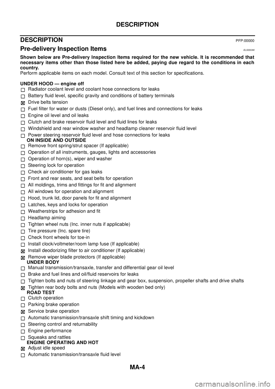
Pre-delivery Inspection ItemsELS000AK
Shown below are Pre-delivery Inspection Items required for the new vehicle. It is recommended that
necessary items other than those listed here be added, paying due regard to the conditions in each
country.
Perform applicable items on each model. Consult text of this section for specifications.
UNDER HOOD — engine off
Radiator coolant level and coolant hose connections for leaks
Battery fluid level, specific gravity and conditions of battery terminals
Drive belts tension
Fuel filter for water or dusts (Diesel only), and fuel lines and connections for leaks
Engine oil level and oil leaks
Clutch and brake reservoir fluid level and fluid lines for leaks
Windshield and rear window washer and headlamp cleaner reservoir fluid level
Power steering reservoir fluid level and hose connections for leaks
ON INSIDE AND OUTSIDE
Remove front spring/strut spacer (If applicable)
Operation of all instruments, gauges, lights and accessories
Operation of horn(s), wiper and washer
Steering lock for operation
Check air conditioner for gas leaks
Front and rear seats, and seat belts for operation
All moldings, trims and fittings for fit and alignment
All windows for operation and alignment
Hood, trunk lid, door panels for fit and alignment
Latches, keys and locks for operation
Weatherstrips for adhesion and fit
Headlamp aiming
Tighten wheel nuts (Inc. inner nuts if applicable)
Tire pressure (Inc. spare tire)
Check front wheels for toe-in
Install clock/voltmeter/room lamp fuse (If applicable)
Install deodorizing filter to air conditioner (If applicable)
Remove wiper blade protectors (If applicable)
UNDER BODY
Manual transmission/transaxle, transfer and differential gear oil level
Brake and fuel lines and oil/fluid reservoirs for leaks
Tighten bolts and nuts of steering linkage and gear box, suspension, propeller shafts and drive shafts
Tighten rear body bolts and nuts (Models with wooden bed only)
ROAD TEST
Clutch operation
Parking brake operation
Service brake operation
Automatic transmission/transaxle shift timing and kickdown
Steering control and returnability
Engine performance
Squeaks and rattles
ENGINE OPERATING AND HOT
Adjust idle speed
Automatic transmission/transaxle fluid level