Page 2418 of 3502
FL-2
PREPARATION
PREPARATIONPFP:00002
Commercial Service ToolsBBS005AD
Tool nameDescription
Fuel tank lock ring wrench Removing and installing fuel tank lock ring
ZZA0122D
Page 2422 of 3502

FL-6
FUEL LEVEL SENSOR UNIT, FUEL FILTER AND FUEL PUMP ASSEMBLY
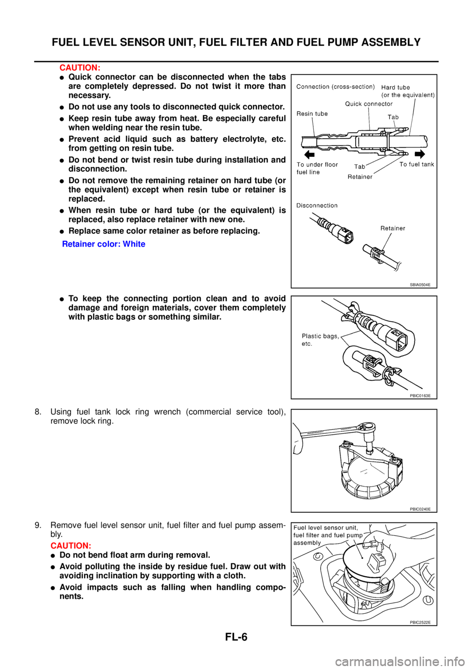
CAUTION:
�Quick connector can be disconnected when the tabs
are completely depressed. Do not twist it more than
necessary.
�Do not use any tools to disconnected quick connector.
�Keep resin tube away from heat. Be especially careful
when welding near the resin tube.
�Prevent acid liquid such as battery electrolyte, etc.
from getting on resin tube.
�Do not bend or twist resin tube during installation and
disconnection.
�Do not remove the remaining retainer on hard tube (or
the equivalent) except when resin tube or retainer is
replaced.
�When resin tube or hard tube (or the equivalent) is
replaced, also replace retainer with new one.
�Replace same color retainer as before replacing.
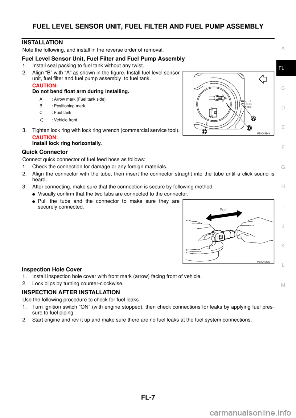
�To keep the connecting portion clean and to avoid
damage and foreign materials, cover them completely
with plastic bags or something similar.
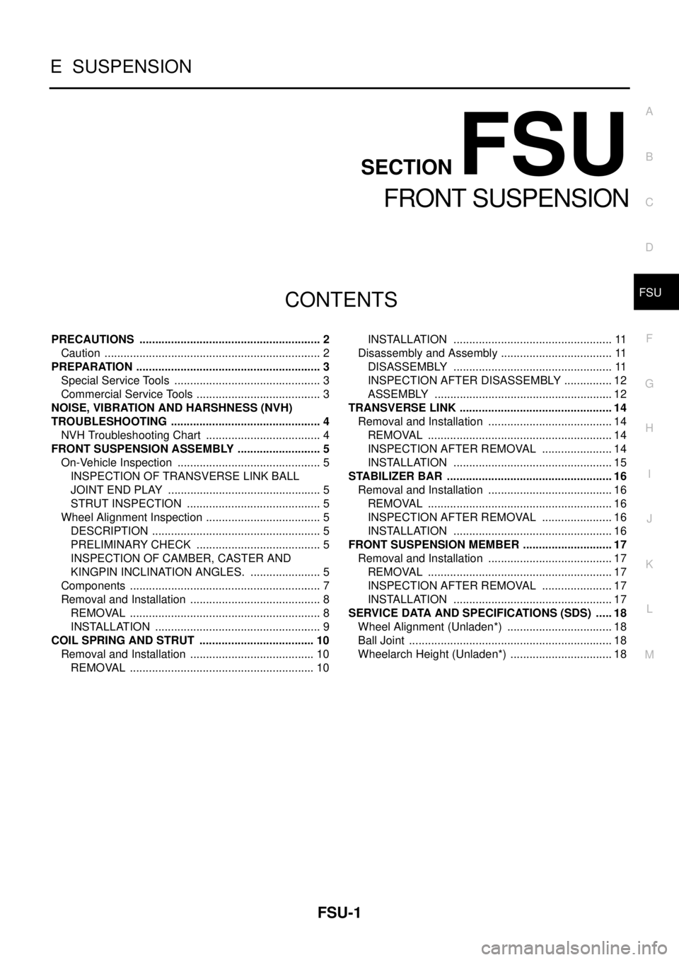
8. Using fuel tank lock ring wrench (commercial service tool),
remove lock ring.
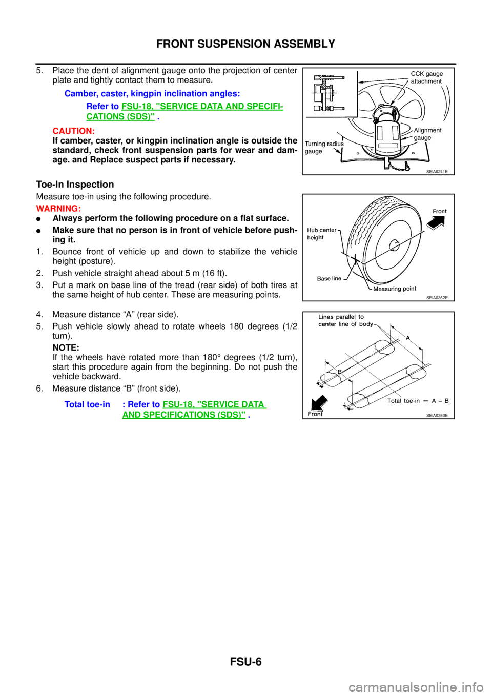
9. Remove fuel level sensor unit, fuel filter and fuel pump assem-
bly.
CAUTION:
�Do not bend float arm during removal.
�Avoid polluting the inside by residue fuel. Draw out with
avoiding inclination by supporting with a cloth.
�Avoid impacts such as falling when handling compo-
nents.Retainer color: White
SBIA0504E
PBIC0163E
PBIC0240E
PBIC2522E
Page 2423 of 3502

FUEL LEVEL SENSOR UNIT, FUEL FILTER AND FUEL PUMP ASSEMBLY
FL-7
C
D
E
F
G
H
I
J
K
L
MA
FL
INSTALLATION
Note the following, and install in the reverse order of removal.
Fuel Level Sensor Unit, Fuel Filter and Fuel Pump Assembly
1. Install seal packing to fuel tank without any twist.
2. Align “B” with “A” as shown in the figure. Install fuel level sensor
unit, fuel filter and fuel pump assembly to fuel tank.
CAUTION:
Do not bend float arm during installing.
3. Tighten lock ring with lock ring wrench (commercial service tool).
CAUTION:
Install lock ring horizontally.
Quick Connector
Connect quick connector of fuel feed hose as follows:
1. Check the connection for damage or any foreign materials.
2. Align the connector with the tube, then insert the connector straight into the tube until a click sound is
heard.
3. After connecting, make sure that the connection is secure by following method.
�Visually confirm that the two tabs are connected to the connector.
�Pull the tube and the connector to make sure they are
securely connected.
Inspection Hole Cover
1. Install inspection hole cover with front mark (arrow) facing front of vehicle.
2. Lock clips by turning counter-clockwise.
INSPECTION AFTER INSTALLATION
Use the following procedure to check for fuel leaks.
1. Turn ignition switch “ON” (with engine stopped), then check connections for leaks by applying fuel pres-
sure to fuel piping.
2. Start engine and rev it up and make sure there are no fuel leaks at the fuel system connections.
A : Arrow mark (Fuel tank side)
B : Positioning mark
C : Fuel tank
: Vehicle front
PBIC4584J
PBIC1653E
Page 2427 of 3502
SERVICE DATA AND SPECIFICATIONS (SDS)
FL-11
C
D
E
F
G
H
I
J
K
L
MA
FL
SERVICE DATA AND SPECIFICATIONS (SDS)PFP:00030
Standard and LimitBBS005AJ
Fuel tank capacity
Approx. 70 (15-3/8 Imp gal)
Fuel recommendationRefer to GI-6
Page 2428 of 3502
FL-12
SERVICE DATA AND SPECIFICATIONS (SDS)
Page 2429 of 3502

FSU-1
FRONT SUSPENSION
E SUSPENSION
CONTENTS
C
D
F
G
H
I
J
K
L
M
SECTION FSU
A
B
FSU
FRONT SUSPENSION
PRECAUTIONS .......................................................... 2
Caution ..................................................................... 2
PREPARATION ........................................................... 3
Special Service Tools ............................................... 3
Commercial Service Tools ........................................ 3
NOISE, VIBRATION AND HARSHNESS (NVH)
TROUBLESHOOTING ................................................ 4
NVH Troubleshooting Chart ..................................... 4
FRONT SUSPENSION ASSEMBLY ........................... 5
On-Vehicle Inspection .............................................. 5
INSPECTION OF TRANSVERSE LINK BALL
JOINT END PLAY ................................................. 5
STRUT INSPECTION ........................................... 5
Wheel Alignment Inspection ..................................... 5
DESCRIPTION ...................................................... 5
PRELIMINARY CHECK ........................................ 5
INSPECTION OF CAMBER, CASTER AND
KINGPIN INCLINATION ANGLES. ....................... 5
Components ............................................................. 7
Removal and Installation .......................................... 8
REMOVAL ............................................................. 8
INSTALLATION ..................................................... 9
COIL SPRING AND STRUT ..................................... 10
Removal and Installation ........................................ 10
REMOVAL ........................................................... 10INSTALLATION ................................................... 11
Disassembly and Assembly .................................... 11
DISASSEMBLY ................................................... 11
INSPECTION AFTER DISASSEMBLY ................ 12
ASSEMBLY ......................................................... 12
TRANSVERSE LINK ................................................. 14
Removal and Installation ........................................ 14
REMOVAL ........................................................... 14
INSPECTION AFTER REMOVAL ....................... 14
INSTALLATION ................................................... 15
STABILIZER BAR ..................................................... 16
Removal and Installation ........................................ 16
REMOVAL ........................................................... 16
INSPECTION AFTER REMOVAL ....................... 16
INSTALLATION ................................................... 16
FRONT SUSPENSION MEMBER ............................. 17
Removal and Installation ........................................ 17
REMOVAL ........................................................... 17
INSPECTION AFTER REMOVAL ....................... 17
INSTALLATION ................................................... 17
SERVICE DATA AND SPECIFICATIONS (SDS) ...... 18
Wheel Alignment (Unladen*) .................................. 18
Ball Joint ................................................................. 18
Wheelarch Height (Unladen*) ................................. 18
Page 2431 of 3502
PREPARATION
FSU-3
C
D
F
G
H
I
J
K
L
MA
B
FSU
PREPARATIONPFP:00002
Special Service Tools BES0003H
Commercial Service ToolsBES0003I
Tool number
Tool nameDescription
KV991040S0
CCK gauge attachment
1. Plate
2. Guide bolts
3. Nuts
4. Springs
5. Center plate
6. KV99104020 Adapter A
a: 72 mm (2.83 in) dia.
7. KV99104030 Adapter B
b: 65 mm (2.56 in) dia.
8. KV99104040 Adapter C
c: 57 mm (2.24 in) dia.
9. KV99104050 Adapter D
d: 53.4 mm (2.102 in) dia.Measuring wheel alignment
ST35652000
Strut attachmentDisassembling and assembling strut
ST3127S000
Preload gauge
1. GG9103000
Torque wrench
2. HT6294000
Socket adapter (1/2″)
3. HT6290000
Socket adapter (3/8″)Measuring rotating torque of ball joint
S-NT498
ZZA0807D
NT124
Tool nameDescription
Spring compressor Removing and installing coil spring
S-NT717
Page 2434 of 3502

FSU-6
FRONT SUSPENSION ASSEMBLY
5. Place the dent of alignment gauge onto the projection of center
plate and tightly contact them to measure.
CAUTION:
If camber, caster, or kingpin inclination angle is outside the
standard, check front suspension parts for wear and dam-
age. and Replace suspect parts if necessary.
Toe-In Inspection
Measure toe-in using the following procedure.
WARNING:
�Always perform the following procedure on a flat surface.
�Make sure that no person is in front of vehicle before push-
ing it.
1. Bounce front of vehicle up and down to stabilize the vehicle
height (posture).
2. Push vehicle straight ahead about 5 m (16 ft).
3. Put a mark on base line of the tread (rear side) of both tires at
the same height of hub center. These are measuring points.
4. Measure distance “A” (rear side).
5. Push vehicle slowly ahead to rotate wheels 180 degrees (1/2
turn).
NOTE:
If the wheels have rotated more than 180° degrees (1/2 turn),
start this procedure again from the beginning. Do not push the
vehicle backward.
6. Measure distance “B” (front side).Camber, caster, kingpin inclination angles:
Refer to FSU-18, "
SERVICE DATA AND SPECIFI-
CATIONS (SDS)" .
SEIA0241E
SEIA0362E
Total toe-in : Refer to FSU-18, "SERVICE DATA
AND SPECIFICATIONS (SDS)" .SEIA0363E