Page 792 of 3502

BL-134
TRUNK LID
Removal and Installation of Trunk Lid Lock BIS000Y3
REMOVAL
1. Remove the trunk lid finisher. Refer to EI-58, "TRUNK ROOM
TRIM & TRUNK LID FINISHER" .
2. Disconnect the emergency handle and trunk lid opener cable
from the clip.
3. After removing the harness connector, remove the mounting
bolts, and remove the trunk lid lock.
INSTALLATION
1. Install in the reverse order of removal.
2. After installing, close the trunk lid. Perform the lock and surface height adjustment. Refer to BL-131, "
Fit-
ting Adjustment" .
3. After installing, check the operation.
Trunk Lid Striker Removal and InstallationBIS000Y4
REMOVAL
1. Remove the trunk rear plate and trunk rear finisher. Refer to EI-
58, "Removal and Installation for Trunk Room Trim" .
2. Remove the mounting bolts, and remove the striker from the
trunk lock support.
INSTALLATION
1. Install in the reverse order of removal.
2. After installing, close the trunk lid. Perform the lock and surface height adjustment. Refer to BL-131, "
Fit-
ting Adjustment" .
3. After installing, check the operation. : 5.8 N·m (0.59 kg-m, 51 in-lb)
PIIB1228E
: 13.5 N·m (1.4 kg-m, 10 ft-lb)
PIIB1229E
Page 824 of 3502

BR-6
BRAKE PEDAL
BRAKE PEDALPFP:46501
Inspection and AdjustmentBFS000BG
Play and clearance inspection between brake pedal and floor panel with pedal depressed.
�Check brake pedal height from dash lower panel (1).
�Adjust height referring to the following specifications.
ADJUSTMENT
1. Loosen stop lamp switch, brake switch and/or ASCD cancel
switch by turning it counterclockwise by 45°.
2. Loosen lock nut “A” on input rod, then rotate input rod to set,
brake pedal to the specified height, and tighten lock nut “A”.
Refer to BR-22, "
COMPONENTS" .
CAUTION:
Make sure the threaded end of input rod stays inside clevis.
3. With pedal pulled and held by hand, press stop lamp switch,
brake switch and/or ASCD cancel switch until its threaded end
contacts bracket.
4. With threaded end of stop lamp switch, brake switch and/or
ASCD cancel switch contacting bracket, rotate switch clockwise
by 45° to secure.
CAUTION:
�Make sure that the clearance “C” between bracket and
end of stop lamp switch, brake switch and/or ASCD can-
cel switch is within the standard.
�When locking stop lamp switch and ASCD cancel switch,
pull brake pedal to avoid moving toward the direction
where switches are being pressed.
5. Check the pedal play.
CAUTION:
Make sure that stop lamps goes off when pedal is released.
6. Start engine to check brake pedal depressed height.
H1Brake pedal free height (from dash lower panel
(1) top surface)195.8 - 205.8 mm
(7.71 - 8.10 in)
H
2
Depressed brake pedal height
[under a force of 490 N (50 kg, 110 lb) with
engine running]More than 115 mm
(4.53 in)
CClearance between the threaded end of stop
lamp switch, brake switch and/or ASCD cancel
switch (2) and bracket (3)0.74 - 1.96 mm
(0.0291 - 0.0772 in)
A Pedal play3-11 mm
(0.12 - 0.43 in)
SFIA2743J
PFIA0824E
Page 826 of 3502
BR-8
BRAKE PEDAL
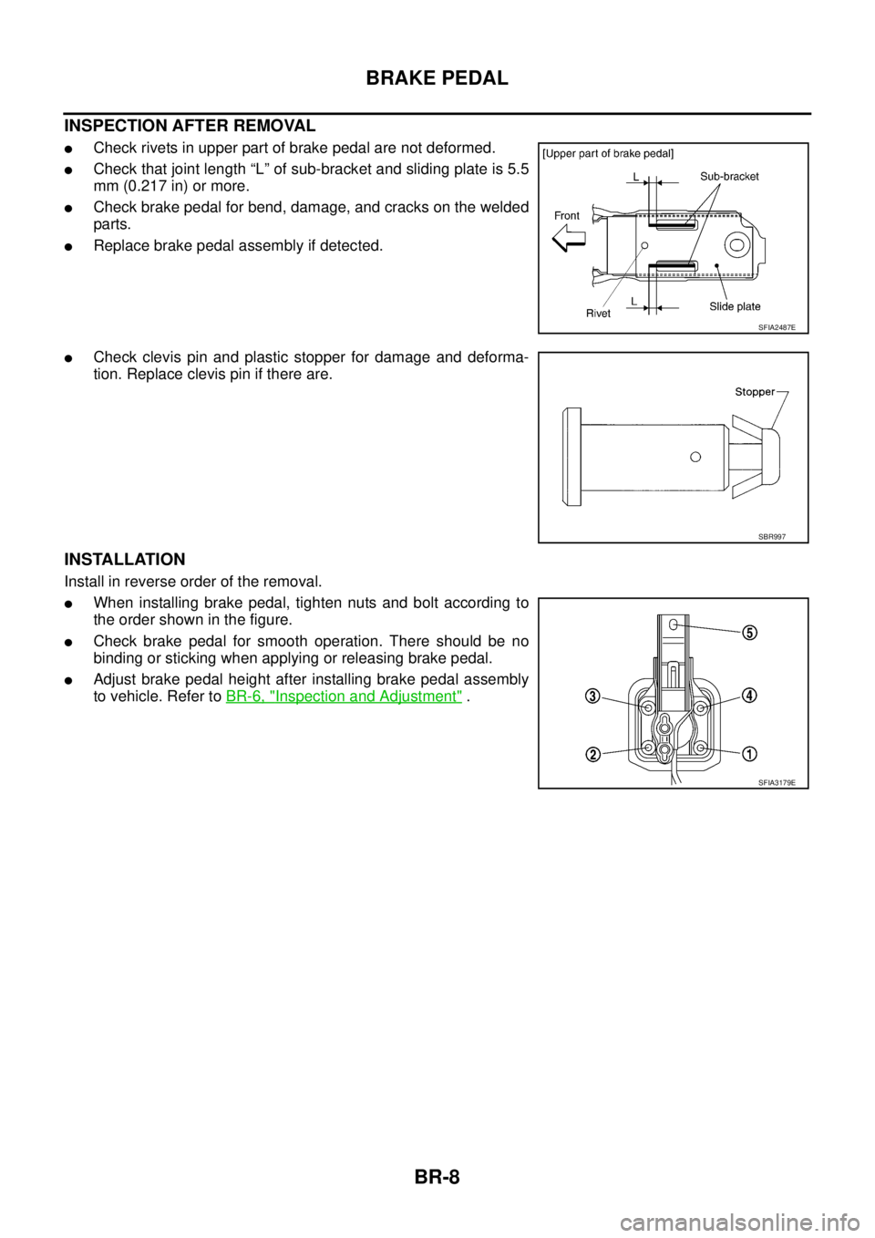
INSPECTION AFTER REMOVAL
�Check rivets in upper part of brake pedal are not deformed.
�Check that joint length “L” of sub-bracket and sliding plate is 5.5
mm (0.217 in) or more.
�Check brake pedal for bend, damage, and cracks on the welded
parts.
�Replace brake pedal assembly if detected.
�Check clevis pin and plastic stopper for damage and deforma-
tion. Replace clevis pin if there are.
INSTALLATION
Install in reverse order of the removal.
�When installing brake pedal, tighten nuts and bolt according to
the order shown in the figure.
�Check brake pedal for smooth operation. There should be no
binding or sticking when applying or releasing brake pedal.
�Adjust brake pedal height after installing brake pedal assembly
to vehicle. Refer to BR-6, "
Inspection and Adjustment" .
SFIA2487E
SBR997
SFIA3179E
Page 841 of 3502
 to brake")
BRAKE BOOSTER
BR-23
C
D
E
G
H
I
J
K
L
MA
B
BR
INSPECTION AFTER REMOVAL
Output Rod Length Inspection
1. Using a handy vacuum pump, apply a vacuum of −66.7 kPa (−
500 mmHg, −19.69 inHg) to brake booster.
2. Check output rod length.
INSTALLATION
1. Loosen lock nut to adjust input rod length so that the length “B”
(shown in the figure) satisfies the specified value.
2. Temporarily tighten lock nut after adjusting the length “B” to the
specified value, and then install brake booster on dash panel.
CAUTION:
Always install gasket between brake booster and dash-
board panel.
3. Install brake booster and brake pedal assembly nuts and bolt,
and then tighten to the specified torque. Refer to BR-7,
"Removal and Installation" .
4. Connect brake pedal with clevis of input rod.
5. Install brake master cylinder. Refer to BR-14, "
Removal and Installation" .
6. Install vacuum hose. Refer to BR-24, "
VACUUM LINES" .
7. Adjust brake pedal free height and the play of brake pedal. Refer to BR-6, "
Inspection and Adjustment" .
8. Tighten input rod lock nut to the specified torque. Refer to BR-22, "
COMPONENTS" .
9. Refill with new brake fluid and bleed air. Refer to BR-11, "
Hydraulic Circuit" . Standard dimension when applying vacuum of −66.7
kPa (−500 mmHg, −19.69 inHg) (Reference value)
Models without VDC : 10.4 mm (0.409 in)
Models with VDC : −6.2 mm (−0.244 in)
SBR208E
Length “B” : 125 mm (4.92 in)
SGIA0060E
Page 858 of 3502

SERVICE DATA AND SPECIFICATIONS (SDS)PFP:00030
General SpecificationsBFS000C7
Unit: mm (in)
Brake PedalBFS000C8
Unit: mm (in)
Brake BoosterBFS000C9
Vacuum")
BR-40
SERVICE DATA AND SPECIFICATIONS (SDS)
SERVICE DATA AND SPECIFICATIONS (SDS)PFP:00030
General SpecificationsBFS000C7
Unit: mm (in)
Brake PedalBFS000C8
Unit: mm (in)
Brake BoosterBFS000C9
Vacuum type
Check ValveBFS000CA
Front Disc BrakeBFS000CB
Unit: mm (in) Front brakeCylinder bore diameter 57.2 (2.252)
Pad length × width × thickness 125.6 × 46.0 × 11.0 (4.94 × 1.81 × 0.433)
Rotor outer diameter × thickness 296 × 24 (11.65 × 0.945)
Rear brake Cylinder bore diameter 34.93 (1.375)
Pad length × width × thickness 83.0 × 33.0 × 8.5 (3.268 × 1.299 × 0.335)
Rotor outer diameter × thickness 292 × 9 (11.50 × 0.354)
Master cylinder Cylinder bore diameter 23.8 (0.94)
Control valve Valve model Electric brake force distribution
Brake booster Booster model M215T
Diaphragm diameterPrimary 228.5 (9.0)
Secondary 203 (8.0)
Recommended brake fluid DOT 3 or DOT 4
Brake pedal height (from dash lower panel top surface) 195.8 - 205.8 (7.71 - 8.10)
Depressed brake pedal height
[under a force of 490 N (50 kg, 110 lb) with engine running]More than 115 (4.53)
Clearance between threaded end of stop lamp switch, brake
switch and/or ASCD cancel switch and bracket 0.74 - 1.96 (0.0291 - 0.0772)
Pedal play3 - 11 (0.12 - 0.43)
Input rod installation standard dimension 125 mm (4.92 in)
Vacuum leakage
[at vacuum of –66.7 kPa (–500 mmHg, –19.69 inHg)]Within 1.3 kPa (10 mmHg, 0.39 inHg) of vacuum for 15 seconds
Brake padStandard thickness 11.0 (0.433)
Repair limit thickness 2.0 (0.079)
Disc rotorStandard thickness 24.0 (0.945)
Wear limit 22.0 (0.866)
Maximum uneven wear (measured at 8 positions) 0.010 (0.0004) or less
Runout limit (with it attached to vehicle) 0.040 (0.0016) or less
Page 880 of 3502
![NISSAN TEANA 2003 Service Manual BRC-20
[ABS]
TROUBLE DIAGNOSIS
×: Applicable
−: Not applicable
Note: Brake warning lamp can be used for EBD warning lamp.
Active TestBFS000D2
CAUTION:
�Do not perform ACTIVE TEST while driving ve](/manual-img/5/57392/w960_57392-879.png "NISSAN TEANA 2003 Service Manual BRC-20
[ABS]
TROUBLE DIAGNOSIS
×: Applicable
−: Not applicable
Note: Brake warning lamp can be used for EBD warning lamp.
Active TestBFS000D2
CAUTION:
�Do not perform ACTIVE TEST while driving ve")
BRC-20
[ABS]
TROUBLE DIAGNOSIS
×: Applicable
−: Not applicable
Note: Brake warning lamp can be used for EBD warning lamp.
Active TestBFS000D2
CAUTION:
�Do not perform ACTIVE TEST while driving vehicle.
�Make sure to completely bleed air from brake system.
�Active test cannot be performed when ABS warning lamp is turned on.
�ABS and brake warning lamps turn on during active test.
OPERATION PROCEDURE
1. Perform “CONSULT-II Starting procedure”. Refer to GI-34, "CONSULT-II Start Procedure" .
2. Touch “ACTIVE TEST” in order on the CONSULT-II screen.
3. The “ SELECT TEST ITEM” screen is displayed.
4. Touch necessary test item.
5. Touch “START” with “MAIN SIGNALS” line inverted.
6. ACTIVE TEST screen will be displayed, so perform the following test.
�Solenoid valve
�ABS motor
NOTE:
�When active test is performed while depressing brake pedal, the pedal height will change, but this is
normal.
�Approximately 10 seconds after operation has begun, “TEST STOP” will be displayed.
�To perform a retest after “TEST STOP” is displayed, touch “BACK” and perform test from step 3.
BATTERY VOLT
(V)×××Condition of voltage supplied to ABS actuator
and electric unit (control unit) is displayed.
EBD SIGNAL
(ON/OFF)——×Condition of EBD operation (ON/OFF) is dis-
played.
ABS SIGNAL
(ON/OFF)——×Condition of ABS operation (ON/OFF) is dis-
played.
EBD FAIL SIG
(ON/OFF)——×Condition of EBD fail-safe signal (ON/OFF) is
displayed.
ABS FAIL SIG
(ON/OFF)——×Condition of ABS fail-safe signal (ON/OFF) is
displayed. Item (Unit)Monitor item selection
Remarks
ECU INPUT
SIGNALSMAIN SIGNALSSELECTION
FROM MENU
SFIA2085E
Page 971 of 3502
RADIATOR (ALUMINUM TYPE)
CO-19
[QR]
C
D
E
F
G
H
I
J
K
L
MA
CO
4. Make sure that the rim is completely crimped down.
5. Make sure that there is no leakage. Refer to CO-19, "
INSPECTION" .
INSPECTION
1. Apply pressure with radiator cap tester adapter (SST) and radia-
tor cap tester (commercial service tool).
WARNING:
To prevent the risk of hose coming undone while under
pressure, securely fasten it down with hose clamp.
CAUTION:
Attach hose to A/T fluid cooler to seal its inlet and outlet.
2. Check for leakage by soaking radiator in water container with
the testing pressure applied.Standard height “H” : 8.0 - 8.4 mm (0.315 - 0.331 in)
SLC554A
Testing pressure
: 157 kPa (1.57 bar, 1.6 kg/cm
2 , 23 psi)
SLC933
SLC934
Page 995 of 3502
RADIATOR (ALUMINUM TYPE)
CO-43
[VQ]
C
D
E
F
G
H
I
J
K
L
MA
CO
4. Make sure that the rim is completely crimped down.
5. Make sure that there is no leakage. Refer to CO-43, "
INSPECTION" .
INSPECTION
1. Apply pressure with radiator cap tester adapter (SST) and radia-
tor cap tester (commercial service tool).
WARNING:
To prevent the risk of hose coming undone while under
pressure, securely fasten it down with hose clamp.
CAUTION:
Attach hose to A/T fluid cooler or CVT fluid cooler to seal its
inlet and outlet.
2. Check for leakage by soaking radiator in water container with
the testing pressure applied.Standard height “H” : 8.0 - 8.4 mm (0.315 - 0.331 in)
SLC554A
Testing pressure
: 157 kPa (1.57 bar, 1.6 kg/cm
2 , 23 psi)
SLC933
SLC934
![NISSAN TEANA 2003 Service Manual RADIATOR (ALUMINUM TYPE)
CO-19
[QR]
C
D
E
F
G
H
I
J
K
L
MA
CO
4. Make sure that the rim is completely crimped down.
5. Make sure that there is no leakage. Refer to CO-19, "
INSPECTION" .
INSPECTION](/manual-img/5/57392/w960_57392-970.png "NISSAN TEANA 2003 Service Manual RADIATOR (ALUMINUM TYPE)
CO-19
[QR]
C
D
E
F
G
H
I
J
K
L
MA
CO
4. Make sure that the rim is completely crimped down.
5. Make sure that there is no leakage. Refer to CO-19, \"
INSPECTION\" .
INSPECTION")
![NISSAN TEANA 2003 Service Manual RADIATOR (ALUMINUM TYPE)
CO-43
[VQ]
C
D
E
F
G
H
I
J
K
L
MA
CO
4. Make sure that the rim is completely crimped down.
5. Make sure that there is no leakage. Refer to CO-43, "
INSPECTION" .
INSPECTION](/manual-img/5/57392/w960_57392-994.png "NISSAN TEANA 2003 Service Manual RADIATOR (ALUMINUM TYPE)
CO-43
[VQ]
C
D
E
F
G
H
I
J
K
L
MA
CO
4. Make sure that the rim is completely crimped down.
5. Make sure that there is no leakage. Refer to CO-43, \"
INSPECTION\" .
INSPECTION")