Page 23 of 3502

A/T FLUID
AT-15
D
E
F
G
H
I
J
K
L
MA
B
AT
6. Check A/T fluid condition.
�If ATF is very dark or smells burned, checking operation of A/
T. Flush cooling system after repair of A/T.
�If ATF contains frictional material (clutches, bands, etc.),
replace radiator and flush cooler line using cleaning solvent
and compressed air after repair of A/T. Refer to CO-37,
"RADIATOR" , CO-40, "RADIATOR (ALUMINUM TYPE)" .
7. Install the removed A/T fluid level gauge in the A/T fluid charging
pipe.
CAUTION:
Firmly fix the A/T fluid level gauge to the A/T fluid charging
pipe using a stopper attached.
Changing A/T FluidBCS000ZM
1. Warm up ATF.
2. Stop engine.
3. Drain ATF from drain plug and refill with new ATF. Always refill same volume with drained ATF.
CAUTION:
Do not reuse drain plug gasket.
4. Run engine at idle speed for 5 minutes.
5. Check A/T fluid level and condition. Refer to AT- 1 4 , "
Checking A/T Fluid" . If ATF is still dirty, repeat steps
2 through 5.
SAT638A
Fluid grade:
Genuine NISSAN ATF Matic Fluid D or equivalent.
Refer to MA-14, "
RECOMMENDED FLUIDS AND LUBRICANTS"
.
Fluid capacity
For QR20DE engine models
: Approx. 8.4 (7-3/8 lmp qt)
For VQ23DE engine models
: Approx. 8.9 (7-7/8 lmp qt)
Drain plug:
: 34 N·m (3.5 kg-m, 25 ft-lb)
Page 28 of 3502
AT-20
A/T CONTROL SYSTEM
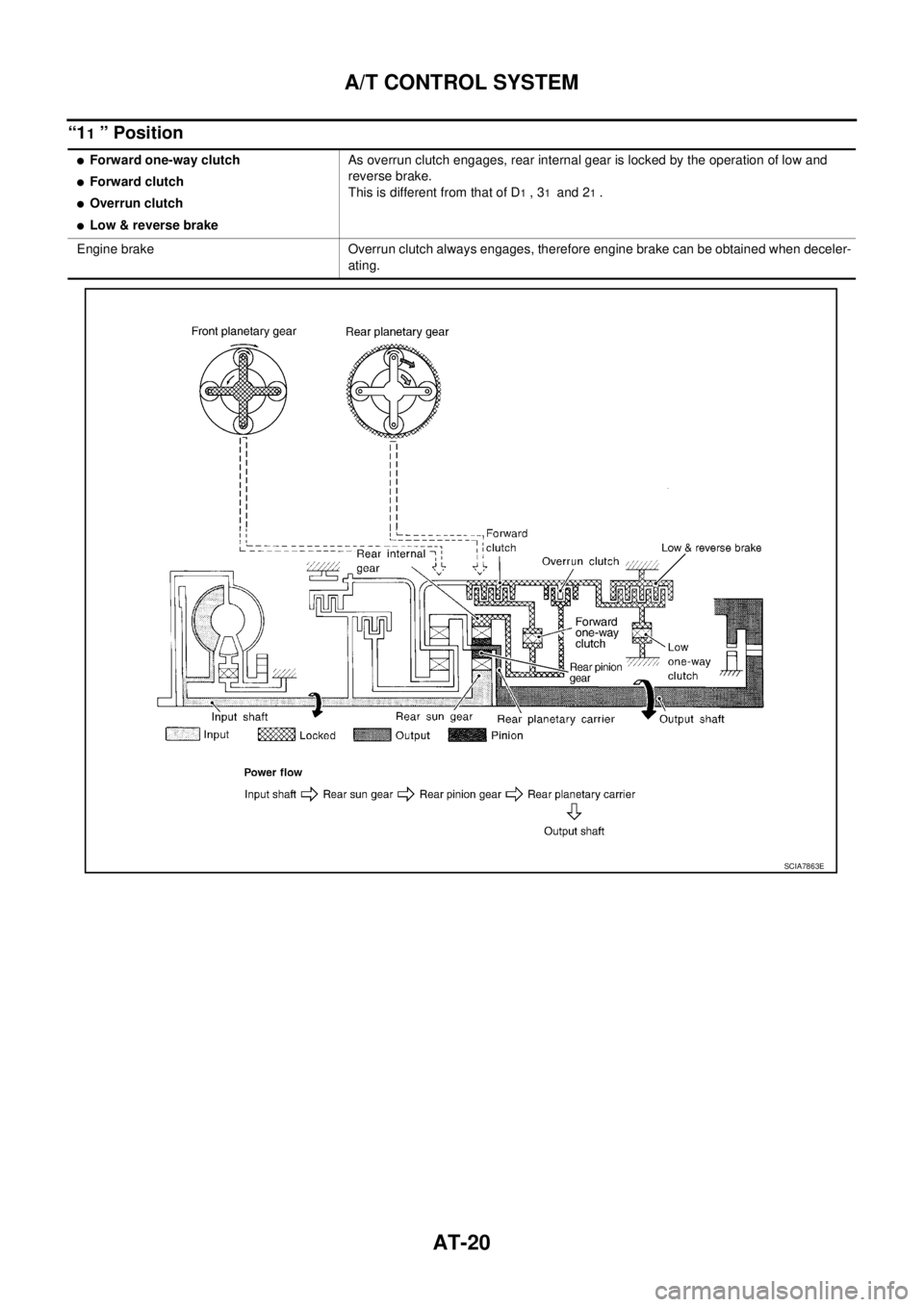
“11 ” Position
�Forward one-way clutch
�Forward clutch
�Overrun clutch
�Low & reverse brakeAs overrun clutch engages, rear internal gear is locked by the operation of low and
reverse brake.
This is different from that of D
1 , 31 and 21 .
Engine brake Overrun clutch always engages, therefore engine brake can be obtained when deceler-
ating.
SCIA7863E
Page 32 of 3502
AT-24
A/T CONTROL SYSTEM
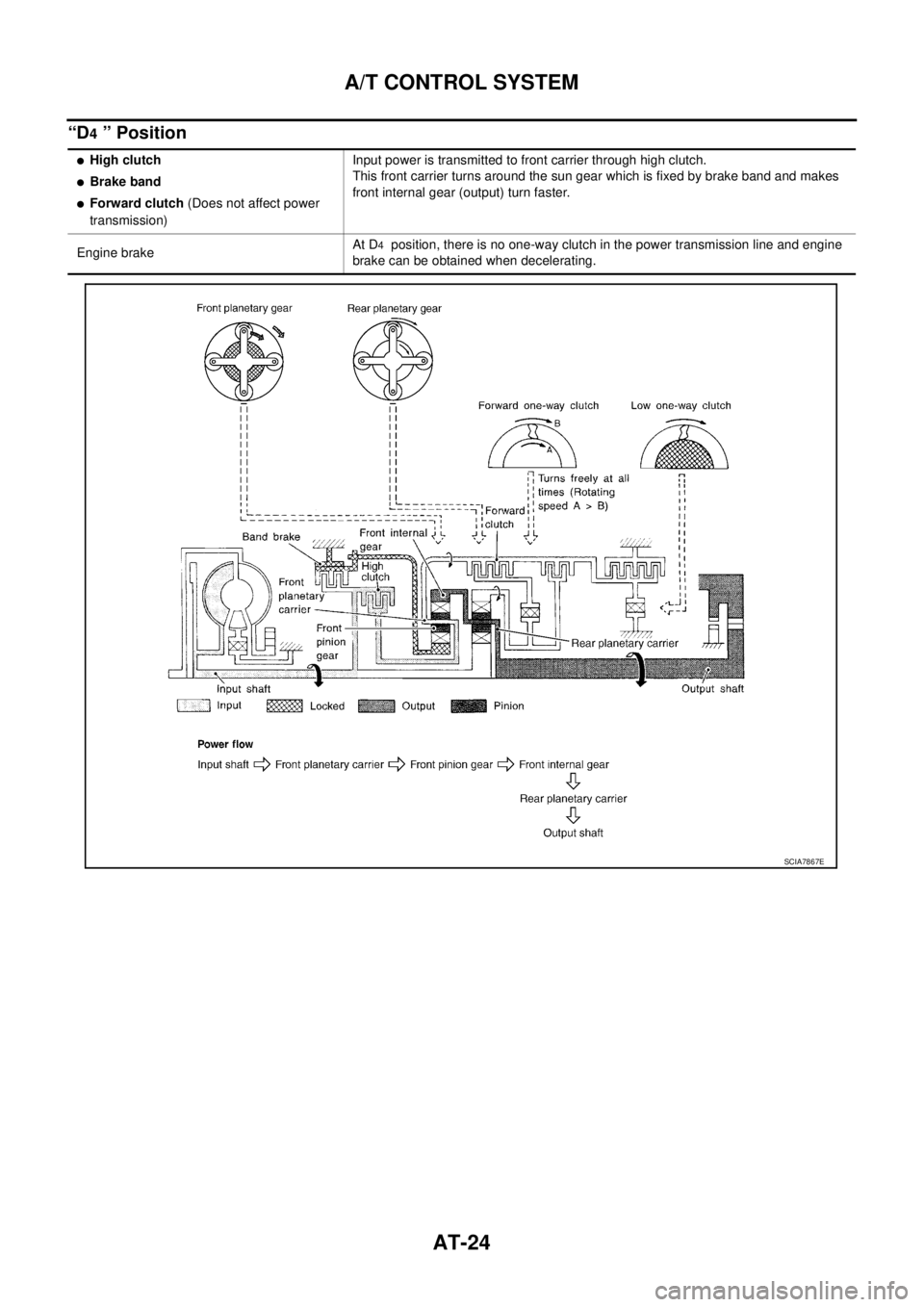
“D4 ” Position
�High clutch
�Brake band
�Forward clutch (Does not affect power
transmission)Input power is transmitted to front carrier through high clutch.
This front carrier turns around the sun gear which is fixed by brake band and makes
front internal gear (output) turn faster.
Engine brakeAt D
4 position, there is no one-way clutch in the power transmission line and engine
brake can be obtained when decelerating.
SCIA7867E
Page 33 of 3502
A/T CONTROL SYSTEM
AT-25
D
E
F
G
H
I
J
K
L
MA
B
AT
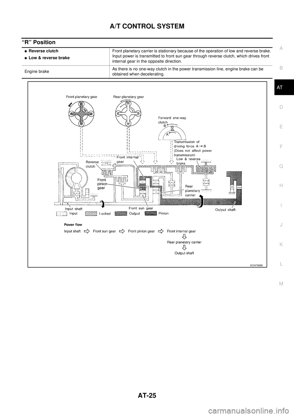
“R” Position
�Reverse clutch
�Low & reverse brakeFront planetary carrier is stationary because of the operation of low and reverse brake.
Input power is transmitted to front sun gear through reverse clutch, which drives front
internal gear in the opposite direction.
Engine brakeAs there is no one-way clutch in the power transmission line, engine brake can be
obtained when decelerating.
SCIA7868E
Page 34 of 3502

AT-26
A/T CONTROL SYSTEM
TCM FunctionBCS000ZP
The function of the TCM is to:
�Receive input signals sent from various switches and sensors.
�Determine required line pressure, shifting point, lock-up operation, and engine brake operation.
�Send required output signals to the respective solenoids.
CONTROL SYSTEM OUTLINE
The automatic transmission senses vehicle operating conditions through various sensors or signals. It always
controls the optimum shift position and reduces shifting and lock-up shocks.
CONTROL SYSTEM DIAGRAM
SWITCHES & SENSORS
�TCM
�ACTUATORS
PNP switch
Accelerator pedal position signal
Closed throttle position signal
Wide open throttle position signal
Engine speed signal
A/T fluid temperature sensor
Revolution sensor
Turbine revolution sensor (power
train revolution sensor)
Vehicle speed signal
3rd position switch signal
Stop lamp switch signalShift control
Line pressure control
Lock-up control
Overrun clutch control
Timing control
Fail-safe control
Self-diagnosis
CONSULT-II communication line
control
CAN systemShift solenoid valve A
Shift solenoid valve B
Overrun clutch solenoid valve
Torque converter clutch solenoid
valve
Line pressure solenoid valve
A/T CHECK indicator lamp
SCIA7869E
Page 35 of 3502
 is a serial communication line for real time application. It is an on-ve")
A/T CONTROL SYSTEM
AT-27
D
E
F
G
H
I
J
K
L
MA
B
AT
CAN CommunicationBCS000ZQ
SYSTEM DESCRIPTION
CAN (Controller Area Network) is a serial communication line for real time application. It is an on-vehicle mul-
tiplex communication line with high data communication speed and excellent error detection ability. Many elec-
tronic control units are equipped onto a vehicle, and each control unit shares information and links with other
control units during operation (not independent). In CAN communication, control units are connected with 2
communication lines (CAN H line, CAN L line) allowing a high rate of information transmission with less wiring.
Each control unit transmits/receives data but selectively reads required data only. For details, refer to LAN-49,
"CAN System Specification Chart" .
Input/Output Signal of TCMBCS000ZR
*1: Spare for vehicle speed sensor·A/T (revolution sensor)
*2: Spare for accelerator pedal position signal
*3: If these input and output signals are different, the TCM triggers the fail-safe function.
*4: Used as a condition for starting self-diagnostics; if self-diagnostics are not started, it is judged that there is some kind of error.
*5: Input by CAN communications.
*6: Output by CAN communications.Control itemLine
pressure
controlVehicle
speed
controlShift
controlLock-up
controlEngine
brake
controlFail-safe
functionSelf-diag-
nostics
function
InputAccelerator pedal position signal
(*5)XXXXX(*3) XX
Vehicle speed sensor A/T
(Revolution sensor)XXXXX(*3) XX
Vehicle speed sensor MTR
(*1)XXXX X
Closed throttle position signal
(*5)(*2) X(*2) XXX(*4) X
Wide open throttle position signal
(*5)(*2) X (*2) X (*4) X
Turbine revolution sensor (Power
train revolution sensor)XX X XX
Engine speed signal X X X X
PNP switch XXXXX(*3) X(*4) X
Stop lamp switch signal
(*5)XX (*4) X
A/T fluid temperature sensors X X X X X X
3rd position switch signal
(*5)XXXX (*4) X
TCM power supply voltage signal X X X X
Out-
putShift solenoid valve A/B X (*3) X X
Line pressure solenoid X (*3) X X
Torque converter clutch solenoid
valveX(*3) XX
Overrun clutch solenoid valve X X (*3) X X
A/T CHECK indicator lamp
(*6)X
Page 42 of 3502

AT-34
TROUBLE DIAGNOSIS
TROUBLE DIAGNOSISPFP:00004
DTC Inspection Priority ChartBCS000ZX
If some DTCs are displayed at the same time, perform inspections one by one based on the following priority
chart.
NOTE:
If DTC “CAN COMM CIRCUIT” is displayed with other DTCs, first perform the trouble diagnosis for
“CAN COMMUNICATION LINE”. Refer to AT- 1 3 3
.
Fail-safeBCS000ZY
The TCM has an electronic Fail-safe mode. This allows the vehicle to be driven even if a major electrical input/
output device circuit is damaged.
Under Fail-safe, the vehicle always runs in third gear, even with a shift lever position of “1”, “2”, “3” or “D”. The
customer may complain of sluggish or poor acceleration.
Always follow the AT- 3 7 , "
WORK FLOW" .
The SELF-DIAGNOSIS results will be as follows:
�The first SELF-DIAGNOSIS will indicate damage to the vehicle speed sensor or the revolution sensor.
�During the next SELF-DIAGNOSIS, performed after checking the sensor, no damages will be indicated.
FAIL-SAFE FUNCTION
The following fail-safe functions allow vehicles to be driven even when sensor, switch or solenoid malfunction
occurs.
Vehicle Speed Sensor 1 (Revolution Sensor)
Vehicle speed sensor 2 signal is input from combination meter.
Accelerator Pedal Position Sensor Signal
TCM controls the throttle opening angle to a predetermined fixed position to enable driving if a malfunctioning
signal is input to TCM.
Park/Neutral Position (PNP) Switch
When the multiple PNP switch signals are input to TCM, the priority of selector lever position becomes “D”·“3”,
“N”, “R”, “2” and “1” in order by internal TCM determination.
The use of 4th gear is inhibited until normal operation resumes. Because the hydraulic circuit of the control
valve is switched by manual valve according to the selector lever position, however, actual operating condition
of vehicle becomes as follows.
Priority Detected items
1 CAN communication line
2 Except above
Actual lever position PNP switch input signal Running status
“P” “P” position and other position signals P
“R” “R” position and other position signals R
“N” “N” position and other position signals N
“D”·“3” “D” position and other position signals D
1 ⇔D2 ⇔D3
“2”“2” position and other position signals (Except “1” position) 21 ⇔22 ⇔23
“2” position and “1” position signals 21 ⇔22
“1”“1” position and other position signals (Except “2” position) 11 ⇔12 ⇔13
“1” position and “2” position signals 11 ⇔12
Page 44 of 3502

AT-36
TROUBLE DIAGNOSIS
How to Perform Trouble Diagnoses for Quick and Accurate RepairBCS000ZZ
INTRODUCTION
The TCM receives a signal from the vehicle speed sensor, accelera-
tor pedal position sensor or PNP switch and provides shift control or
lock-up control via A/T solenoid valves.
Input and output signals must always be correct and stable in the
operation of the A/T system. The A/T system must be in good oper-
ating condition and be free of valve seizure, solenoid valve malfunc-
tion, etc.
It is much more difficult to diagnose a malfunction that occurs inter-
mittently rather than continuously. Most intermittent malfunctions are
caused by poor electric connections or improper wiring. In this case,
careful checking of suspected circuits may help prevent the replace-
ment of good parts.
A visual check only, may not find the cause of the malfunctions. A
road test with CONSULT-II or a circuit tester connected should be
performed. Follow the AT- 3 7 , "
WORK FLOW" .
Before undertaking actual checks, take a few minutes to talk with a
customer who approaches with a drivability complaint. The customer
can supply good information about such malfunctions, especially
intermittent ones. Find out what symptoms are present and under
what conditions they occur. A “DIAGNOSTIC WORKSHEET” like the
example (AT- 3 8 , "
DIAGNOSTIC WORKSHEET" ) should be used.
Start your diagnosis by looking for “conventional” malfunctions first.
This will help troubleshoot drivability malfunctions on an electroni-
cally controlled engine vehicle.
Also check related Service bulletins for information.
SAT631IA
SAT632I
SEF234G