Page 21 of 229
GEC384A
AIR CONDITIONER CONTROLYD25DDTi
Wiring Diagram (Cont'd)
EC-4017
Page 103 of 229
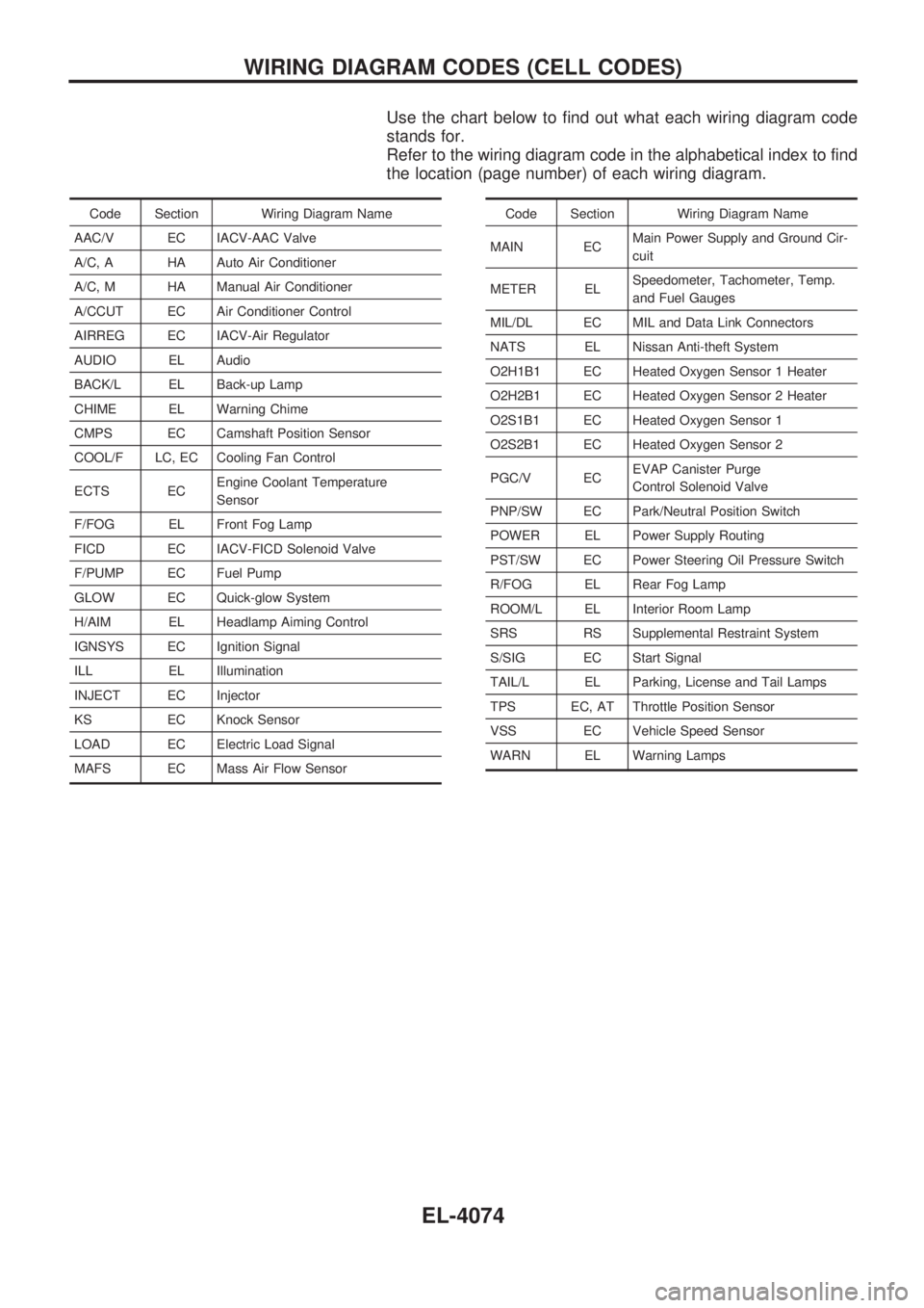
Use the chart below to find out what each wiring diagram code
stands for.
Refer to the wiring diagram code in the alphabetical index to find
the location (page number) of each wiring diagram.
Code Section Wiring Diagram Name
AAC/V EC IACV-AAC Valve
A/C, A HA Auto Air Conditioner
A/C, M HA Manual Air Conditioner
A/CCUT EC Air Conditioner Control
AIRREG EC IACV-Air Regulator
AUDIO EL Audio
BACK/L EL Back-up Lamp
CHIME EL Warning Chime
CMPS EC Camshaft Position Sensor
COOL/F LC, EC Cooling Fan Control
ECTS ECEngine Coolant Temperature
Sensor
F/FOG EL Front Fog Lamp
FICD EC IACV-FICD Solenoid Valve
F/PUMP EC Fuel Pump
GLOW EC Quick-glow System
H/AIM EL Headlamp Aiming Control
IGNSYS EC Ignition Signal
ILL EL Illumination
INJECT EC Injector
KS EC Knock Sensor
LOAD EC Electric Load Signal
MAFS EC Mass Air Flow SensorCode Section Wiring Diagram Name
MAIN ECMain Power Supply and Ground Cir-
cuit
METER ELSpeedometer, Tachometer, Temp.
and Fuel Gauges
MIL/DL EC MIL and Data Link Connectors
NATS EL Nissan Anti-theft System
O2H1B1 EC Heated Oxygen Sensor 1 Heater
O2H2B1 EC Heated Oxygen Sensor 2 Heater
O2S1B1 EC Heated Oxygen Sensor 1
O2S2B1 EC Heated Oxygen Sensor 2
PGC/V ECEVAP Canister Purge
Control Solenoid Valve
PNP/SW EC Park/Neutral Position Switch
POWER EL Power Supply Routing
PST/SW EC Power Steering Oil Pressure Switch
R/FOG EL Rear Fog Lamp
ROOM/L EL Interior Room Lamp
SRS RS Supplemental Restraint System
S/SIG EC Start Signal
TAIL/L EL Parking, License and Tail Lamps
TPS EC, AT Throttle Position Sensor
VSS EC Vehicle Speed Sensor
WARN EL Warning Lamps
WIRING DIAGRAM CODES (CELL CODES)
EL-4074
Page 106 of 229
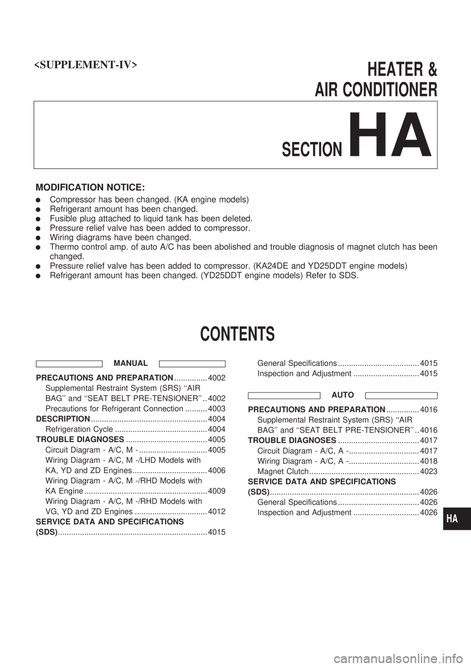
HEATER &
AIR CONDITIONER
SECTION
HA
MODIFICATION NOTICE:
lCompressor has been changed. (KA engine models)
lRefrigerant amount has been changed.
lFusible plug attached to liquid tank has been deleted.
lPressure relief valve has been added to compressor.
lWiring diagrams have been changed.
lThermo control amp. of auto A/C has been abolished and trouble diagnosis of magnet clutch has been
changed.
lPressure relief valve has been added to compressor. (KA24DE and YD25DDT engine models)
lRefrigerant amount has been changed. (YD25DDT engine models) Refer to SDS.
CONTENTS
MANUAL
PRECAUTIONS AND PREPARATION............... 4002
Supplemental Restraint System (SRS) ``AIR
BAG'' and ``SEAT BELT PRE-TENSIONER'' .. 4002
Precautions for Refrigerant Connection .......... 4003
DESCRIPTION..................................................... 4004
Refrigeration Cycle .......................................... 4004
TROUBLE DIAGNOSES..................................... 4005
Circuit Diagram - A/C, M - ............................... 4005
Wiring Diagram - A/C, M -/LHD Models with
KA, YD and ZD Engines .................................. 4006
Wiring Diagram - A/C, M -/RHD Models with
KA Engine ........................................................ 4009
Wiring Diagram - A/C, M -/RHD Models with
VG, YD and ZD Engines ................................. 4012
SERVICE DATA AND SPECIFICATIONS
(SDS).................................................................... 4015General Specifications ..................................... 4015
Inspection and Adjustment .............................. 4015
AUTO
PRECAUTIONS AND PREPARATION............... 4016
Supplemental Restraint System (SRS) ``AIR
BAG'' and ``SEAT BELT PRE-TENSIONER'' .. 4016
TROUBLE DIAGNOSES..................................... 4017
Circuit Diagram - A/C, A -................................ 4017
Wiring Diagram - A/C, A -................................ 4018
Magnet Clutch .................................................. 4023
SERVICE DATA AND SPECIFICATIONS
(SDS).................................................................... 4026
General Specifications ..................................... 4026
Inspection and Adjustment .............................. 4026
HA
Page 130 of 229
VA
NoteNote
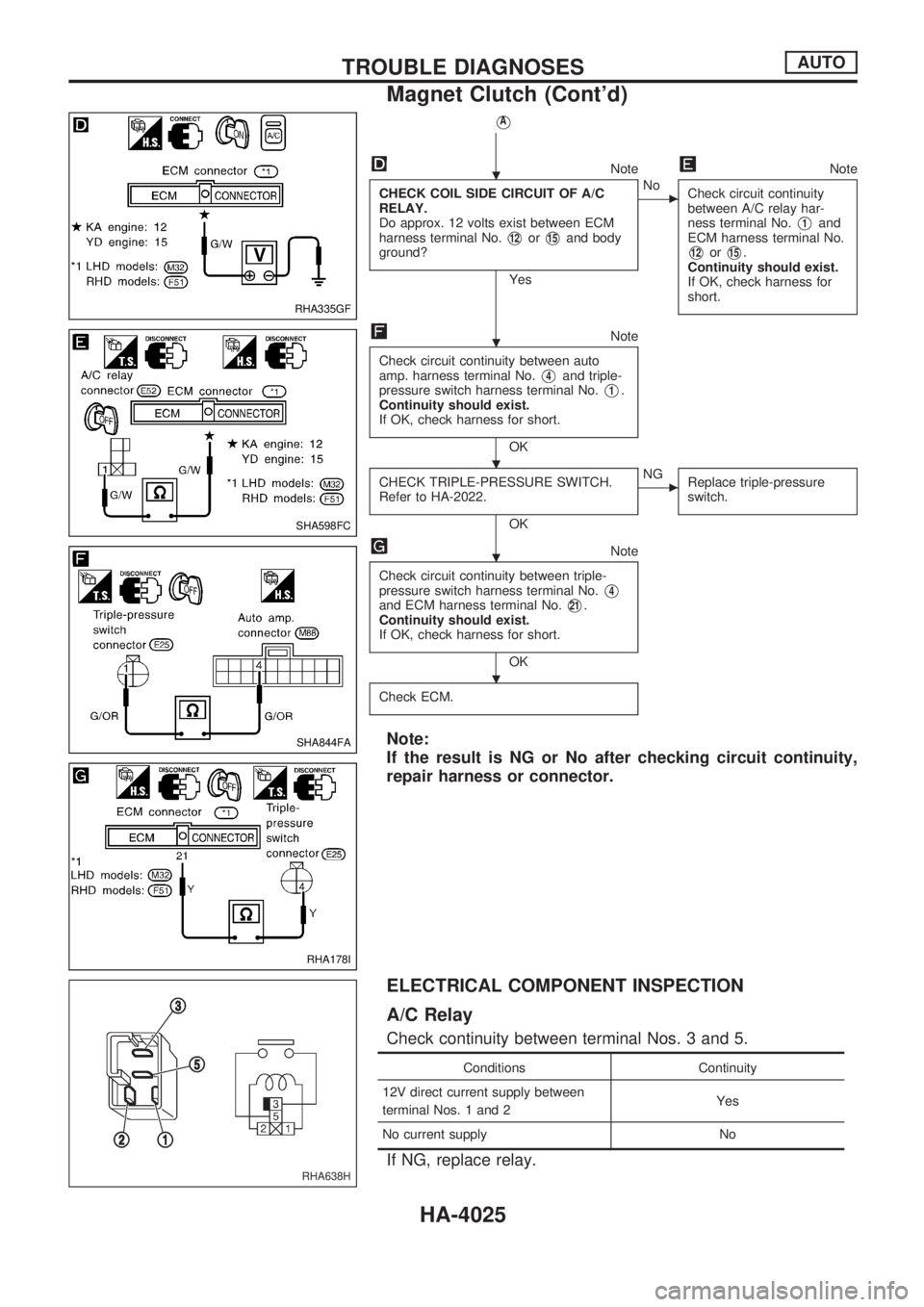
CHECK COIL SIDE CIRCUIT OF A/C
RELAY.
Do approx. 12 volts exist between ECM
harness terminal No.
V12orV15and body
ground?
Yes
cNo
Check circuit continuity
between A/C relay har-
ness terminal No.
V1and
ECM harness terminal No.
V12orV15.
Continuity should exist.
If OK, check harness for
short.
Note
Check circuit continuity between auto
amp. harness terminal No.
V4and triple-
pressure switch harness terminal No.
V1.
Continuity should exist.
If OK, check harness for short.
OK
CHECK TRIPLE-PRESSURE SWITCH.
Refer to HA-2022.
OK
cNG
Replace triple-pressure
switch.
Note
Check circuit continuity between triple-
pressure switch harness terminal No.
V4and ECM harness terminal No.V21.
Continuity should exist.
If OK, check harness for short.
OK
Check ECM.
Note:
If the result is NG or No after checking circuit continuity,
repair harness or connector.
ELECTRICAL COMPONENT INSPECTION
A/C Relay
Check continuity between terminal Nos. 3 and 5.
Conditions Continuity
12V direct current supply between
terminal Nos. 1 and 2Yes
No current supply No
If NG, replace relay.
RHA335GF
SHA598FC
SHA844FA
RHA178I
RHA638H
.
.
. .
.
.
TROUBLE DIAGNOSESAUTO
Magnet Clutch (Cont'd)
HA-4025
Page 133 of 229
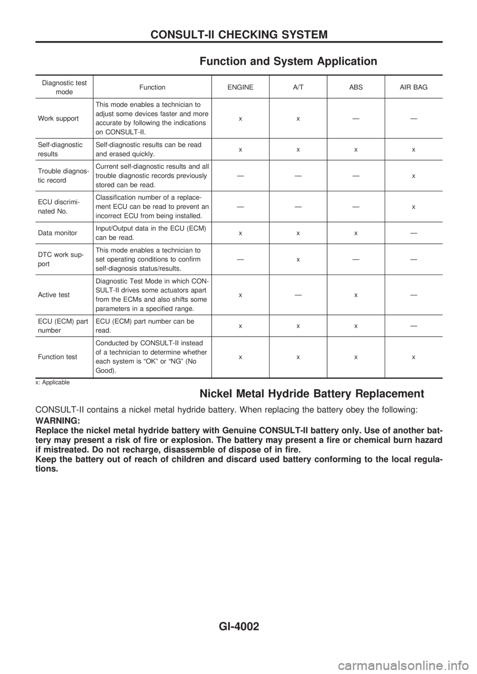
Function and System Application
Diagnostic test
modeFunction ENGINE A/T ABS AIR BAG
Work supportThis mode enables a technician to
adjust some devices faster and more
accurate by following the indications
on CONSULT-II.xxÐÐ
Self-diagnostic
resultsSelf-diagnostic results can be read
and erased quickly.xxxx
Trouble diagnos-
tic recordCurrent self-diagnostic results and all
trouble diagnostic records previously
stored can be read.ÐÐÐ x
ECU discrimi-
nated No.Classification number of a replace-
ment ECU can be read to prevent an
incorrect ECU from being installed.ÐÐÐ x
Data monitorInput/Output data in the ECU (ECM)
can be read.xxxÐ
DTC work sup-
portThis mode enables a technician to
set operating conditions to confirm
self-diagnosis status/results.ÐxÐÐ
Active testDiagnostic Test Mode in which CON-
SULT-II drives some actuators apart
from the ECMs and also shifts some
parameters in a specified range.xÐxÐ
ECU (ECM) part
numberECU (ECM) part number can be
read.xxxÐ
Function testConducted by CONSULT-II instead
of a technician to determine whether
each system is ªOKº or ªNGº (No
Good).xxxx
x: Applicable
Nickel Metal Hydride Battery Replacement
CONSULT-II contains a nickel metal hydride battery. When replacing the battery obey the following:
WARNING:
Replace the nickel metal hydride battery with Genuine CONSULT-II battery only. Use of another bat-
tery may present a risk of fire or explosion. The battery may present a fire or chemical burn hazard
if mistreated. Do not recharge, disassemble of dispose of in fire.
Keep the battery out of reach of children and discard used battery conforming to the local regula-
tions.
CONSULT-II CHECKING SYSTEM
GI-4002
Page 229 of 229
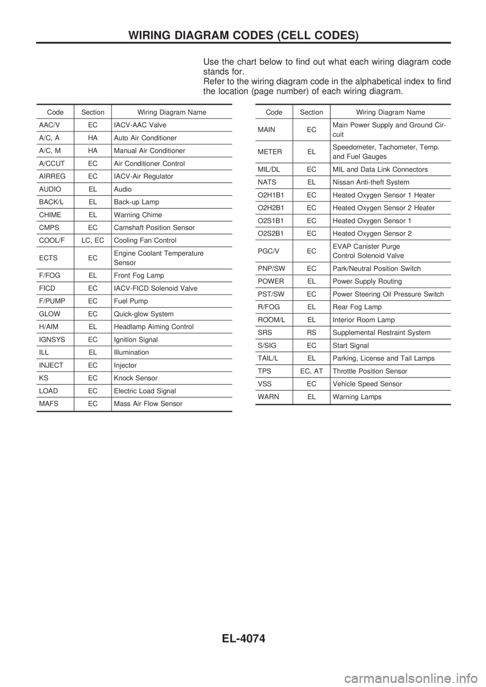
Use the chart below to find out what each wiring diagram code
stands for.
Refer to the wiring diagram code in the alphabetical index to find
the location (page number) of each wiring diagram.
Code Section Wiring Diagram Name
AAC/V EC IACV-AAC Valve
A/C, A HA Auto Air Conditioner
A/C, M HA Manual Air Conditioner
A/CCUT EC Air Conditioner Control
AIRREG EC IACV-Air Regulator
AUDIO EL Audio
BACK/L EL Back-up Lamp
CHIME EL Warning Chime
CMPS EC Camshaft Position Sensor
COOL/F LC, EC Cooling Fan Control
ECTS ECEngine Coolant Temperature
Sensor
F/FOG EL Front Fog Lamp
FICD EC IACV-FICD Solenoid Valve
F/PUMP EC Fuel Pump
GLOW EC Quick-glow System
H/AIM EL Headlamp Aiming Control
IGNSYS EC Ignition Signal
ILL EL Illumination
INJECT EC Injector
KS EC Knock Sensor
LOAD EC Electric Load Signal
MAFS EC Mass Air Flow SensorCode Section Wiring Diagram Name
MAIN ECMain Power Supply and Ground Cir-
cuit
METER ELSpeedometer, Tachometer, Temp.
and Fuel Gauges
MIL/DL EC MIL and Data Link Connectors
NATS EL Nissan Anti-theft System
O2H1B1 EC Heated Oxygen Sensor 1 Heater
O2H2B1 EC Heated Oxygen Sensor 2 Heater
O2S1B1 EC Heated Oxygen Sensor 1
O2S2B1 EC Heated Oxygen Sensor 2
PGC/V ECEVAP Canister Purge
Control Solenoid Valve
PNP/SW EC Park/Neutral Position Switch
POWER EL Power Supply Routing
PST/SW EC Power Steering Oil Pressure Switch
R/FOG EL Rear Fog Lamp
ROOM/L EL Interior Room Lamp
SRS RS Supplemental Restraint System
S/SIG EC Start Signal
TAIL/L EL Parking, License and Tail Lamps
TPS EC, AT Throttle Position Sensor
VSS EC Vehicle Speed Sensor
WARN EL Warning Lamps
WIRING DIAGRAM CODES (CELL CODES)
EL-4074