2003 NISSAN MAXIMA clock
[x] Cancel search: clockPage 45 of 247

2 Instruments and controlsInstrument panel ....................................................... 2-2
Meters and gauges ................................................... 2-3
Speedometer and odometer ................................ 2-4
Tachometer .......................................................... 2-4
Engine coolant temperature gauge ...................... 2-5
Fuel gauge ........................................................... 2-5
Compass display (if so equipped)............................. 2-6
Warning/indicator lights and audible reminders ........ 2-9
Checking bulbs ..................................................... 2-9
Warning lights....................................................... 2-9
Indicator lights .................................................... 2-12
Audible reminders .............................................. 2-13
Security systems ..................................................... 2-14
Vehivle security system ...................................... 2-14
Nissan Vehicle Immobilizer System .................. 2-15
Windshield wiper and washer switch ...................... 2-16
Rear window and outside mirror (if so equipped)
defogger switch ....................................................... 2-17
Headlight and turn signal switch ............................. 2-18
Xenon headlights................................................ 2-19
Headlight switch ................................................. 2-19
Turn signal switch .............................................. 2-21
Fog light switch (if so equipped) ............................. 2-21
Hazard warning flasher switch ................................ 2-22Horn......................................................................... 2-22
Heated seats (if so equipped) ................................. 2-23
Heated steering wheel (if so equipped) .................. 2-24
Traction control system (TCS) cancel switch
(if so equipped) ....................................................... 2-24
Power outlet ............................................................ 2-24
Cigarette lighter and ashtray (accessory) ............... 2-25
Storage .................................................................... 2-26
Trays................................................................... 2-26
Sunglasses holder .............................................. 2-26
Cup holder .......................................................... 2-27
Glove box ........................................................... 2-27
Console box ....................................................... 2-28
Cargo net (if so equipped) ................................. 2-28
Windows .................................................................. 2-29
Power windows .................................................. 2-29
Sunroof (if so equipped) ......................................... 2-31
Automatic sunroof .............................................. 2-31
Clock ....................................................................... 2-32
Adjusting the time............................................... 2-32
Trip computer .......................................................... 2-32
Interior light ............................................................. 2-34
Ceiling................................................................. 2-34
Personal light .......................................................... 2-35
Z
02.7.12/A33-D/V5.0
X
Page 47 of 247

1. Instrument brightness control switch
(P.2-20)
2. Headlight, fog light (if so equipped) and turn
signal switch (P.2-18)
3. Traction control system (TCS) cancel
switch (if so equipped) (P.2-24)
4. Meters/gauges (P.2-3)
5. Rear window and outside mirror (if so
equipped) defroster switch Ð type B
(P.2-17)
6. Windshield wiper/washer switch (P.2-16)
7. Ventilator (P.4-2)
8. Rear window and outside mirror (if so
equipped) defroster switch Ð Type Auto
A/C (P.2-17)
9. Heater/air conditioner control (P.4-3) or
radio/cassette player (4-16)
10. Clock (P.2-32)
11. Security indicator light (P.2-14)
12. Radio/cassette player (P.4-16)/CD player
(P.4-16) or Navigation system*
13. Passenger supplemental air bag (P.1-8)
14. Fuse box cover (P.8-24)
15. Automatic drive positioner system cancel
switch (if so equipped) (P.3-18)
16. Heated steering switch (if so equipped)
(P.2-23)
17. Outside mirror remote control (P.3-15)
18. Steering switch for audio control (P.4-28)
and trip computer (P.2-32)
19. Driver supplemental air bag (P.1-8)
20. Tilting steering wheel lock lever (P.3-14)
21. Cruise control main/set switch (P.5-14)
22. Ignition switch/steering lock (P.5-4)
SIC1736
INSTRUMENT PANEL2-2
Instruments and controls
Z
02.7.12/A33-D/V5.0
X
Page 65 of 247
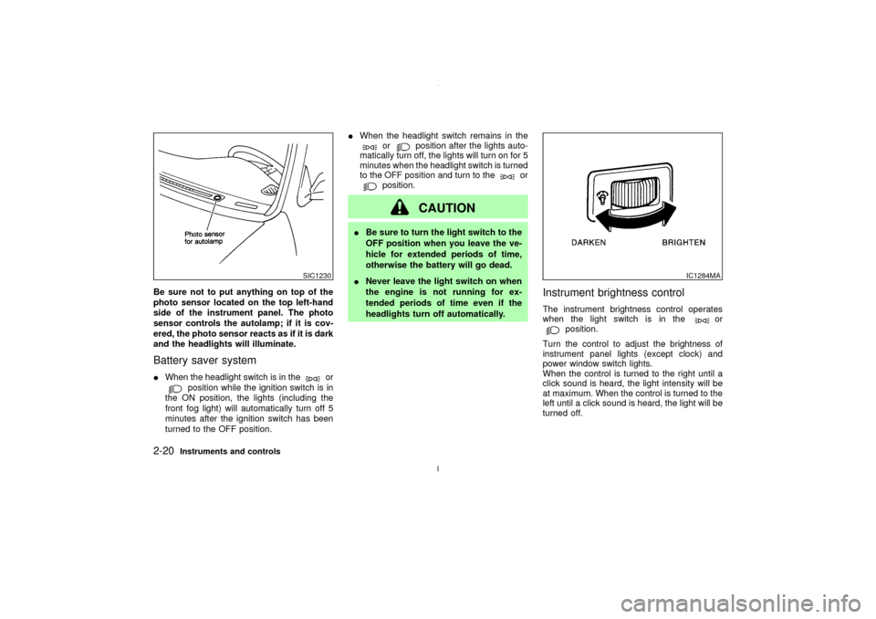
Be sure not to put anything on top of the
photo sensor located on the top left-hand
side of the instrument panel. The photo
sensor controls the autolamp; if it is cov-
ered, the photo sensor reacts as if it is dark
and the headlights will illuminate.Battery saver systemIWhen the headlight switch is in the
or
position while the ignition switch is in
the ON position, the lights (including the
front fog light) will automatically turn off 5
minutes after the ignition switch has been
turned to the OFF position.IWhen the headlight switch remains in the
or
position after the lights auto-
matically turn off, the lights will turn on for 5
minutes when the headlight switch is turned
to the OFF position and turn to the
or
position.
CAUTION
IBe sure to turn the light switch to the
OFF position when you leave the ve-
hicle for extended periods of time,
otherwise the battery will go dead.
INever leave the light switch on when
the engine is not running for ex-
tended periods of time even if the
headlights turn off automatically.
Instrument brightness controlThe instrument brightness control operates
when the light switch is in the
or
position.
Turn the control to adjust the brightness of
instrument panel lights (except clock) and
power window switch lights.
When the control is turned to the right until a
click sound is heard, the light intensity will be
at maximum. When the control is turned to the
left until a click sound is heard, the light will be
turned off.
SIC1230
IC1284MA
2-20
Instruments and controls
Z
02.7.12/A33-D/V5.0
X
Page 77 of 247
sunroof is opened. However, it must be closed
manually.
WARNING
IIn an accident you could be thrown
from the vehicle through an open
sunroof. Always use seat belts and
child restraints.
IDo not allow anyone to stand up or
extend any portion of their body out
of the opening while the vehicle is in
motion or while the sunroof is clos-
ing.
CAUTION
IRemove water drops, snow, ice or
sand from the sunroof before open-
ing.
IDo not place any heavy object on the
sunroof or surrounding area.If the sunroof does not closeHave your NISSAN dealer check and repair
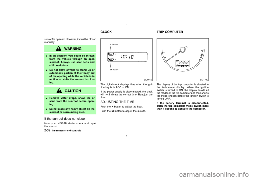
the sunroof.The digital clock displays time when the igni-
tion key is in ACC or ON.
If the power supply is disconnected, the clock
will not indicate the correct time. Readjust the
time.
ADJUSTING THE TIMEPush theHbutton to adjust the hour.
Push theMbutton to adjust the minute.The display of the trip computer is situated in
the tachometer display. When the ignition
switch is turned to ON, the display scrolls all
the modes of the trip computer and then shows
the mode chosen before the ignition switch is
turned OFF.
If the battery terminal is disconnected,
push the trip computer mode switch more
than 1 second to activate the computer.
SIC0910
SIC1749
CLOCK TRIP COMPUTER
2-32
Instruments and controls
Z
02.7.12/A33-D/V5.0
X
Page 96 of 247
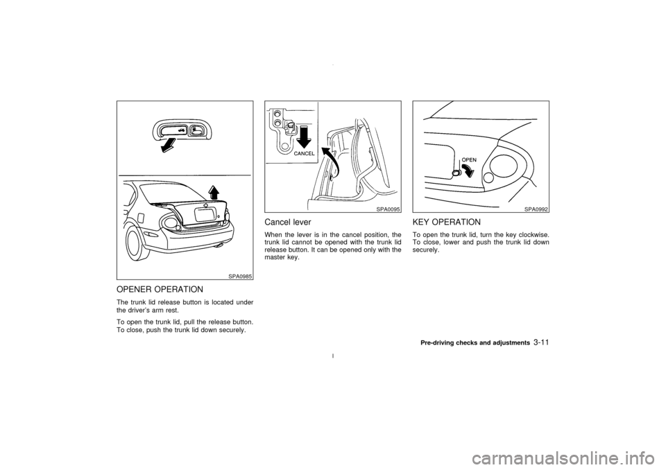
OPENER OPERATIONThe trunk lid release button is located under
the driver's arm rest.
To open the trunk lid, pull the release button.
To close, push the trunk lid down securely.
Cancel leverWhen the lever is in the cancel position, the
trunk lid cannot be opened with the trunk lid
release button. It can be opened only with the
master key.
KEY OPERATIONTo open the trunk lid, turn the key clockwise.
To close, lower and push the trunk lid down
securely.
SPA0985
SPA0095
SPA0992
Pre-driving checks and adjustments
3-11
Z
02.7.12/A33-D/V5.0
X
Page 98 of 247
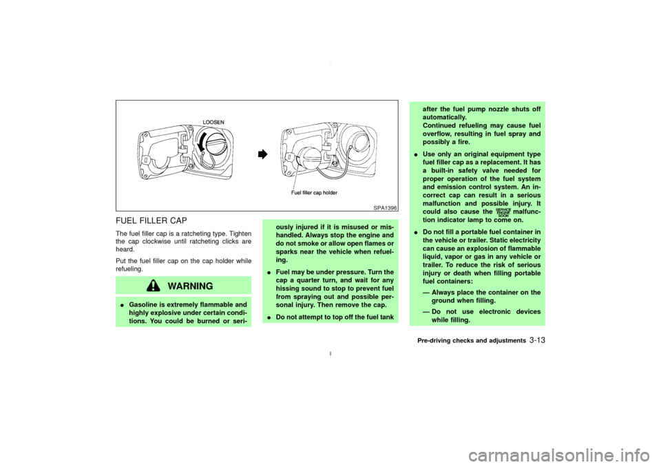
FUEL FILLER CAPThe fuel filler cap is a ratcheting type. Tighten
the cap clockwise until ratcheting clicks are
heard.
Put the fuel filler cap on the cap holder while
refueling.
WARNING
IGasoline is extremely flammable and
highly explosive under certain condi-
tions. You could be burned or seri-ously injured if it is misused or mis-
handled. Always stop the engine and
do not smoke or allow open flames or
sparks near the vehicle when refuel-
ing.
IFuel may be under pressure. Turn the
cap a quarter turn, and wait for any
hissing sound to stop to prevent fuel
from spraying out and possible per-
sonal injury. Then remove the cap.
IDo not attempt to top off the fuel tankafter the fuel pump nozzle shuts off
automatically.
Continued refueling may cause fuel
overflow, resulting in fuel spray and
possibly a fire.
IUse only an original equipment type
fuel filler cap as a replacement. It has
a built-in safety valve needed for
proper operation of the fuel system
and emission control system. An in-
correct cap can result in a serious
malfunction and possible injury. It
could also cause the
malfunc-
tion indicator lamp to come on.
IDo not fill a portable fuel container in
the vehicle or trailer. Static electricity
can cause an explosion of flammable
liquid, vapor or gas in any vehicle or
trailer. To reduce the risk of serious
injury or death when filling portable
fuel containers:
Ð Always place the container on the
ground when filling.
Ð Do not use electronic devices
while filling.
SPA1396
Pre-driving checks and adjustments
3-13
Z
02.7.12/A33-D/V5.0
X
Page 118 of 247

FM RADIO RECEPTIONRange: FM range is normally limited to 25 to
30 miles (40 to 48 km), with monaural (single
channel) FM having slightly more range than
stereo FM. External influences may some-
times interfere with FM station reception even
if the FM station is within 25 miles (40 km). The
strength of the FM signal is directly related to
the distance between the transmitter and re-
ceiver. FM signals follow a line-of-sight path,
exhibiting many of the same characteristics as
light. For example they will reflect off objects.
Fade and drift: As your vehicle moves awayfrom a station transmitter, the signals will tend
to fade and/or drift.
Static and flutter: During signal interference
from buildings, large hills or due to antenna
position, usually in conjunction with increased
distance from the station transmitter, static or
flutter can be heard. This can be reduced by
adjusting the treble control counterclockwise
to reduce treble response.
Multipath reception: Because of the reflective
characteristics of FM signals, direct and re-
flected signals reach the receiver at the same
time. The signals may cancel each other,
resulting in momentary flutter or loss of sound.
AM RADIO RECEPTIONAM signals, because of their low frequency,
can bend around objects and skip along the
ground. In addition, the signals can be
bounced off the ionosphere and bent back to
earth. Because of these characteristics. AM
signals are also subject to interference as they
travel from transmitter to receiver.
Fading: Occurs while the vehicle is passing
through freeway underpasses or in areas with
many tall buildings. It can also occur for sev-
eral seconds during ionospheric turbulence
even in areas where no obstacles exist.
Static: Caused by thunderstorms, electricalpower lines, electric signs and even traffic
lights.
AUDIO OPERATION
PRECAUTIONS
Cassette playerITo maintain good quality sound,
NISSAN recommends using cassette
tapes of 60 minutes or shorter in length.
ICassette tapes should be removed from
the player when not in use. Store cas-
settes in their protective cases and away
from direct sunlight, heat, dust, mois-
ture and magnetic sources.
IDirect sunlight can cause the cassette to
become deformed. The use of deformed
cassettes may cause the cassette to jam
in the player.
IDo not use cassettes with labels which
are peeling and loose. If used, the label
could jam in the player.
IIf a cassette has loose tape, insert a
pencil through one of the cassette hubs
and rewind the tape firmly around the
hubs. Loose tape may cause tape jam-
ming and wavering sound quality.
IOver a period of time, the playback
SAA0306
Heater, air conditioner and audio systems
4-13
Z
02.7.12/A33-D/V5.0
X
Page 140 of 247
LOCK position, proceed as follows to remove
the key:
1. Move the selector lever into the P (Park)
position.
2. Turn the ignition key slightly in the ON
direction.
3. Turn the key toward the LOCK position.
4. Remove the key.
If the key is removed from the ignition switch,
the selector lever cannot be moved from P
(Park) position.The selector lever can be
moved if the ignition switch is in the ON
position and the foot brake pedal is de-
pressed.
There is an OFF position in between LOCK
and ACC, although it does not show on the
lock cylinder. When the ignition is in OFF the
steering wheel is not locked.
In order for the steering wheel to be locked, it
must be turned about 1/6 of a turn counter-
clockwise from the straight up position.
To lock the steering wheel, turn the key to
the LOCK position. Remove the key. To
unlock the steering wheel, insert the key
and turn it gently while rotating the steer-
ing wheel slightly right and left.
WARNING
Never remove or turn the key to the
LOCK position while driving. The steer-
ing wheel will lock. This may cause the
driver to lose control of the vehicle and
could result in serious vehicle damage
and/or personal injury.
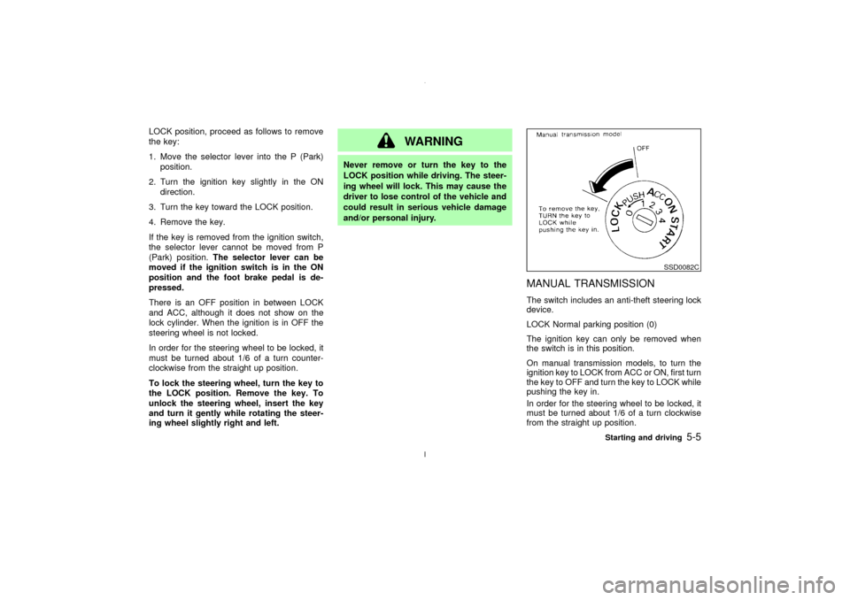
MANUAL TRANSMISSIONThe switch includes an anti-theft steering lock
device.
LOCK Normal parking position (0)
The ignition key can only be removed when
the switch is in this position.
On manual transmission models, to turn the
ignition key to LOCK from ACC or ON, first turn
the key to OFF and turn the key to LOCK while
pushing the key in.
In order for the steering wheel to be locked, it
must be turned about 1/6 of a turn clockwise
from the straight up position.
SSD0082C
Starting and driving
5-5
Z
02.7.12/A33-D/V5.0
X