2003 NISSAN ALMERA N16 spark
[x] Cancel search: sparkPage 8 of 3189
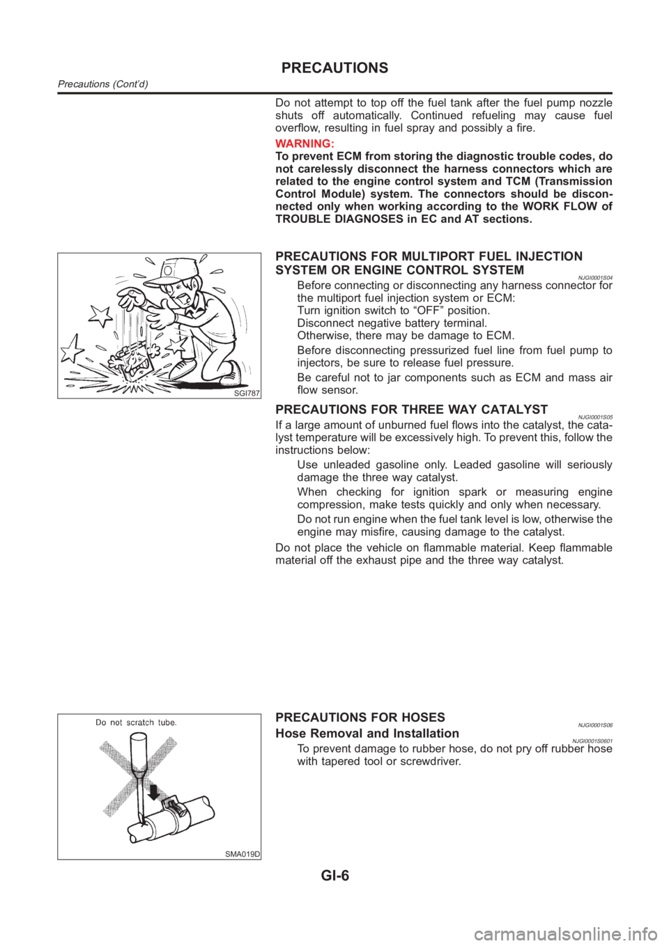
Do not attempt to top off the fuel tank after the fuel pump nozzle
shuts off automatically. Continued refueling may cause fuel
overflow, resulting in fuel spray and possibly a fire.
WARNING:
To prevent ECM from storing the diagnostic trouble codes, do
not carelessly disconnect the harness connectors which are
related to the engine control system and TCM (Transmission
Control Module) system. The connectors should be discon-
nected only when working according to the WORK FLOW of
TROUBLE DIAGNOSES in EC and AT sections.
SGI787
PRECAUTIONS FOR MULTIPORT FUEL INJECTION
SYSTEM OR ENGINE CONTROL SYSTEM
NJGI0001S04Before connecting or disconnecting any harness connector for
the multiport fuel injection system or ECM:
Turn ignition switch to “OFF” position.
Disconnect negative battery terminal.
Otherwise, there may be damage to ECM.
Before disconnecting pressurized fuel line from fuel pump to
injectors, be sure to release fuel pressure.
Be careful not to jar components such as ECM and mass air
flow sensor.
PRECAUTIONS FOR THREE WAY CATALYSTNJGI0001S05If a large amount of unburned fuel flows into the catalyst, the cata-
lyst temperature will be excessively high. To prevent this, follow the
instructions below:
Use unleaded gasoline only. Leaded gasoline will seriously
damage the three way catalyst.
When checking for ignition spark or measuring engine
compression, make tests quickly and only when necessary.
Do not run engine when the fuel tank level is low, otherwise the
engine may misfire, causing damage to the catalyst.
Do not place the vehicle on flammable material. Keep flammable
material off the exhaust pipe and the three way catalyst.
SMA019D
PRECAUTIONS FOR HOSESNJGI0001S06Hose Removal and InstallationNJGI0001S0601To prevent damage to rubber hose, do not pry off rubber hose
with tapered tool or screwdriver.
PRECAUTIONS
Precautions (Cont’d)
GI-6
Page 60 of 3189
NJMA0005
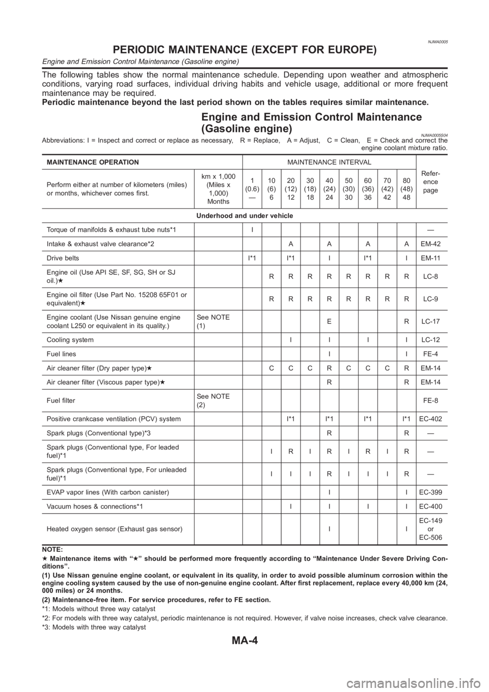
The following tables show the normal maintenance schedule. Depending upon weather and atmospheric
conditions, varying road surfaces, individual driving habits and vehicle usage, additional or more frequent
maintenance may be required.
Periodic maintenance beyond the last period shown on the tables requires similar maintenance.
Engine and Emission Control Maintenance
(Gasoline engine)
NJMA0005S04Abbreviations: I = Inspect and correct or replace as necessary, R = Replace, A = Adjust, C = Clean, E = Check and correct the
engine coolant mixture ratio.
MAINTENANCE OPERATIONMAINTENANCE INTERVAL
Refer-
ence
page Perform either at number of kilometers (miles)
or months, whichever comes first.kmx1,000
(Miles x
1,000)
Months1
(0.6)
—10
(6)
620
(12)
1230
(18)
1840
(24)
2450
(30)
3060
(36)
3670
(42)
4280
(48)
48
Underhood and under vehicle
Torque of manifolds & exhaust tube nuts*1 I —
Intake & exhaust valve clearance*2AAAAEM-42
Drive belts I*1 I*1 I I*1 I EM-11
Engine oil (Use API SE, SF, SG, SH or SJ
oil.)★RRRRRRRRLC-8
Engine oil filter (Use Part No. 15208 65F01 or
equivalent)★RRRRRRRRLC-9
Engine coolant (Use Nissan genuine engine
coolant L250 or equivalent in its quality.)See NOTE
(1)E R LC-17
Cooling systemIIIILC-12
Fuel linesI I FE-4
Air cleaner filter (Dry paper type)★CCCRCCCREM-14
Air cleaner filter (Viscous paper type)★R R EM-14
Fuel filterSee NOTE
(2)FE-8
Positive crankcase ventilation (PCV) system I*1 I*1 I*1 I*1 EC-402
Spark plugs (Conventional type)*3 R R —
Spark plugs (Conventional type, For leaded
fuel)*1IRIRIRIR —
Spark plugs (Conventional type, For unleaded
fuel)*1IIIRIIIR —
EVAP vapor lines (With carbon canister) I I EC-399
Vacuum hoses & connections*1IIIIEC-400
Heated oxygen sensor (Exhaust gas sensor) I IEC-149
or
EC-506
NOTE:
★Maintenance items with “★” should be performed more frequently according to “Maintenance Under Severe Driving Con-
ditions”.
(1) Use Nissan genuine engine coolant, or equivalent in its quality, in order to avoid possible aluminum corrosion within the
engine cooling system caused by the use of non-genuine engine coolant. After first replacement, replace every 40,000 km (24,
000 miles) or 24 months.
(2) Maintenance-free item. For service procedures, refer to FE section.
*1: Models without three way catalyst
*2: For models with three way catalyst, periodic maintenance is not requir
ed. However, if valve noise increases, check valve clearance.
*3: Models with three way catalyst
PERIODIC MAINTENANCE (EXCEPT FOR EUROPE)
Engine and Emission Control Maintenance (Gasoline engine)
MA-4
Page 63 of 3189
NJMA0043
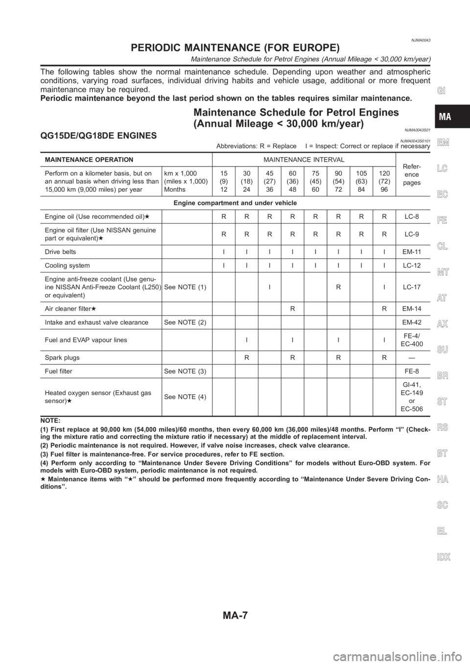
The following tables show the normal maintenance schedule. Depending upon weather and atmospheric
conditions, varying road surfaces, individual driving habits and vehicle usage, additional or more frequent
maintenance may be required.
Periodic maintenance beyond the last period shown on the tables requires similar maintenance.
Maintenance Schedule for Petrol Engines
(Annual Mileage < 30,000 km/year)
NJMA0043S01QG15DE/QG18DE ENGINESNJMA0043S0101Abbreviations: R = Replace I = Inspect: Correct or replace if necessary
MAINTENANCE OPERATIONMAINTENANCE INTERVAL
Refer-
ence
pages Perform on a kilometer basis, but on
an annual basis when driving less than
15,000 km (9,000 miles) per yearkmx1,000
(miles x 1,000)
Months15
(9)
1230
(18)
2445
(27)
3660
(36)
4875
(45)
6090
(54)
72105
(63)
84120
(72)
96
Engine compartment and under vehicle
Engine oil (Use recommended oil)★RRRRRRRRLC-8
Engine oil filter (Use NISSAN genuine
part or equivalent)★RRRRRRRRLC-9
Drive beltsIIIIIIIIEM-11
Cooling systemIIIIIIIILC-12
Engine anti-freeze coolant (Use genu-
ine NISSAN Anti-Freeze Coolant (L250)
or equivalent)See NOTE (1) I R I LC-17
Air cleaner filter★R R EM-14
Intake and exhaust valve clearance See NOTE (2) EM-42
Fuel and EVAP vapour linesIIIIFE-4/
EC-400
Spark plugsRRRR—
Fuel filter See NOTE (3) FE-8
Heated oxygen sensor (Exhaust gas
sensor)★See NOTE (4)GI-41,
EC-149
or
EC-506
NOTE:
(1) First replace at 90,000 km (54,000 miles)/60 months, then every 60,000km (36,000 miles)/48 months. Perform “I” (Check-
ing the mixture ratio and correcting the mixture ratio if necessary) at themiddle of replacement interval.
(2) Periodic maintenance is not required. However, if valve noise increases, check valve clearance.
(3) Fuel filter is maintenance-free. For service procedures, refer to FE section.
(4) Perform only according to “Maintenance Under Severe Driving Conditions” for models without Euro-OBD system. For
models with Euro-OBD system, periodic maintenance is not required.
★Maintenance items with “★” should be performed more frequently according to “Maintenance Under Severe Driving Con-
ditions”.
GI
EM
LC
EC
FE
CL
MT
AT
AX
SU
BR
ST
RS
BT
HA
SC
EL
IDX
PERIODIC MAINTENANCE (FOR EUROPE)
Maintenance Schedule for Petrol Engines (Annual Mileage < 30,000 km/year)
MA-7
Page 69 of 3189
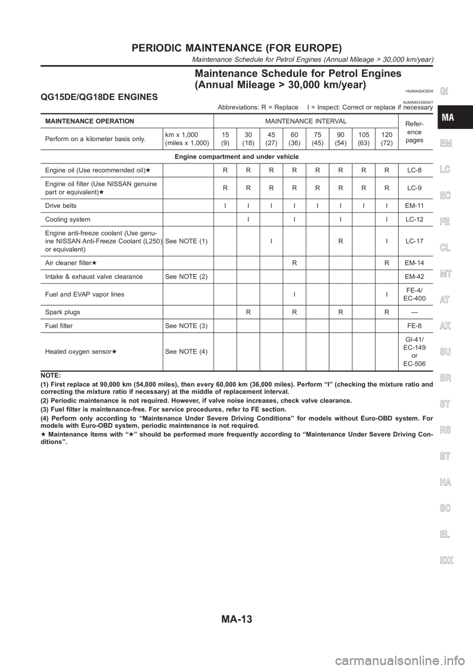
Maintenance Schedule for Petrol Engines
(Annual Mileage > 30,000 km/year)
=NJMA0043S04QG15DE/QG18DE ENGINESNJMA0043S0401Abbreviations: R = Replace I = Inspect: Correct or replace if necessary
MAINTENANCE OPERATIONMAINTENANCE INTERVAL
Refer-
ence
pages Perform on a kilometer basis only.kmx1,000
(miles x 1,000)15
(9)30
(18)45
(27)60
(36)75
(45)90
(54)105
(63)120
(72)
Engine compartment and under vehicle
Engine oil (Use recommended oil)★RRRRRRRRLC-8
Engine oil filter (Use NISSAN genuine
part or equivalent)★RRRRRRRRLC-9
Drive beltsIIIIIIIIEM-11
Cooling systemIIIILC-12
Engine anti-freeze coolant (Use genu-
ine NISSAN Anti-Freeze Coolant (L250)
or equivalent)See NOTE (1) I R I LC-17
Air cleaner filter★R R EM-14
Intake & exhaust valve clearance See NOTE (2) EM-42
Fuel and EVAP vapor lines I IFE-4/
EC-400
Spark plugsRRRR—
Fuel filter See NOTE (3) FE-8
Heated oxygen sensor★See NOTE (4)GI-41/
EC-149
or
EC-506
NOTE:
(1) First replace at 90,000 km (54,000 miles), then every 60,000 km (36,000miles). Perform “I” (checking the mixture ratio and
correcting the mixture ratio if necessary) at the middle of replacement interval.
(2) Periodic maintenance is not required. However, if valve noise increases, check valve clearance.
(3) Fuel filter is maintenance-free. For service procedures, refer to FE section.
(4) Perform only according to “Maintenance Under Severe Driving Conditions” for models without Euro-OBD system. For
models with Euro-OBD system, periodic maintenance is not required.
★Maintenance items with “★” should be performed more frequently according to “Maintenance Under Severe Driving Con-
ditions”.
GI
EM
LC
EC
FE
CL
MT
AT
AX
SU
BR
ST
RS
BT
HA
SC
EL
IDX
PERIODIC MAINTENANCE (FOR EUROPE)
Maintenance Schedule for Petrol Engines (Annual Mileage > 30,000 km/year)
MA-13
Page 79 of 3189
EM-1
ENGINE MECHANICAL
B ENGINE
CONTENTS
C
D
E
F
G
H
I
J
K
L
M
SECTION
A
EM
ENGINE MECHANICAL
QG
PRECAUTIONS .......................................................... 3
Precautions for Drain Coolant .................................. 3
Precautions for Disconnecting Fuel Piping .............. 3
Precautions for Removal and Disassembly ............. 3
Precautions for Inspection, Repair and Replace-
ment ......................................................................... 3
Precautions for Assembly and Installation ............... 3
Parts Requiring Angular Tightening ......................... 3
Precautions for Liquid Gasket .................................. 4
REMOVAL OF LIQUID GASKET SEALING .......... 4
LIQUID GASKET APPLICATION PROCEDURE ..... 4
PREPARATION ........................................................... 5
Special Service Tools ............................................... 5
Commercial Service Tools ........................................ 7
NOISE, VIBRATION, AND HARSHNESS (NVH)
TROUBLESHOOTING ................................................ 9
NVH Troubleshooting —Engine Noise ..................... 9
Use the Chart Below to Help You Find the Cause
of the Symptom. ..................................................... 10
DRIVE BELTS ............................................................11
Checking Drive Belts ............................................... 11
Tension Adjustment ................................................ 12
POWER STEERING PUMP AND WATER PUMP
BELT ................................................................... 12
ALTERNATOR AND AIR CONDITIONER COM-
PRESSOR BELT ................................................. 12
Removal and Installation ........................................ 13
REMOVAL ........................................................... 13
INSTALLATION ................................................... 13
AIR CLEANER AND AIR DUCT ............................... 14
Removal and Installation ........................................ 14
REMOVAL ........................................................... 14
INSTALLATION ................................................... 14
Changing Air Cleaner Element ............................... 15
INTAKE MANIFOLD ................................................. 16
Removal and Installation ........................................ 16
REMOVAL ........................................................... 16
INSPECTION AFTER REMOVAL ....................... 18
INSTALLATION ................................................... 18EXHAUST MANIFOLD AND CATALYTIC CON-
VERTER .................................................................... 19
Removal and Installation ........................................ 19
REMOVAL ........................................................... 19
INSPECTION AFTER REMOVAL ....................... 20
INSTALLATION ................................................... 20
Disassembly and Assembly .................................... 21
DISASSEMBLY ................................................... 21
ASSEMBLY ......................................................... 21
OIL PAN AND OIL STRAINER ..............................
... 22
Removal and Installation ........................................ 22
REMOVAL ........................................................... 22
INSTALLATION ................................................... 23
INSPECTION AFTER INSTALLATION ................ 23
IGNITION COIL ......................................................... 24
Removal and Installation ........................................ 24
REMOVAL ........................................................... 24
INSTALLATION ................................................... 24
SPARK PLUG (CONVENTIONAL) ........................... 25
Removal and Installation ........................................ 25
REMOVAL ........................................................... 25
INSPECTION AFTER REMOVAL ....................... 25
INSTALLATION ................................................... 25
FUEL INJECTOR AND FUEL TUBE ........................ 26
Removal and Installation ........................................ 26
REMOVAL ........................................................... 26
INSTALLATION ................................................... 27
INSPECTION AFTER INSTALLATION ................ 28
ROCKER COVER ..................................................... 29
Removal and Installation ........................................ 29
REMOVAL ........................................................... 29
INSTALLATION ................................................... 30
CAMSHAFT .............................................................. 32
Removal and Installation ........................................ 32
REMOVAL ........................................................... 32
INSTALLATION ................................................... 35
Page 85 of 3189
![NISSAN ALMERA N16 2003 Electronic Repair Manual PREPARATION
EM-7
[QG]
C
D
E
F
G
H
I
J
K
L
MA
EM
Commercial Service ToolsEBS00LPV
ST16610001
Pilot bushing pullerRemoving pilot bushing
KV101056S0*
Rear gear stopper
1. KV10105620
Adapter
2. KV10105610](/manual-img/5/57350/w960_57350-84.png "NISSAN ALMERA N16 2003 Electronic Repair Manual PREPARATION
EM-7
[QG]
C
D
E
F
G
H
I
J
K
L
MA
EM
Commercial Service ToolsEBS00LPV
ST16610001
Pilot bushing pullerRemoving pilot bushing
KV101056S0*
Rear gear stopper
1. KV10105620
Adapter
2. KV10105610")
PREPARATION
EM-7
[QG]
C
D
E
F
G
H
I
J
K
L
MA
EM
Commercial Service ToolsEBS00LPV
ST16610001
Pilot bushing pullerRemoving pilot bushing
KV101056S0*
Rear gear stopper
1. KV10105620
Adapter
2. KV10105610
Plate assemblyPreventing crankshaft from rotating Tool number
To o l n a m eDescription
NT045
NT773
To o l n a m eDescription
Spark plug wrench Removing and installing spark plug
Crankshaft pulley puller Removing crankshaft pulley
Manual lift table caddy Removing and installing engine
Valve seat cutter set Finishing valve seat dimensions
Piston ring expander Removing and installing piston ring
NT047
PBIC0887E
ZZA1210D
NT048
NT030
Page 102 of 3189
![NISSAN ALMERA N16 2003 Electronic Repair Manual EM-24
[QG]
IGNITION COIL
IGNITION COIL
PFP:22448
Removal and InstallationEBS00LQ7
REMOVAL
1. Remove ignition coil harness connector from ignition coil.
2. Remove ignition coil.
CAUTION:
●Do not shoc](/manual-img/5/57350/w960_57350-101.png "NISSAN ALMERA N16 2003 Electronic Repair Manual EM-24
[QG]
IGNITION COIL
IGNITION COIL
PFP:22448
Removal and InstallationEBS00LQ7
REMOVAL
1. Remove ignition coil harness connector from ignition coil.
2. Remove ignition coil.
CAUTION:
●Do not shoc")
EM-24
[QG]
IGNITION COIL
IGNITION COIL
PFP:22448
Removal and InstallationEBS00LQ7
REMOVAL
1. Remove ignition coil harness connector from ignition coil.
2. Remove ignition coil.
CAUTION:
●Do not shock it.
●Do not disassemble it.
INSTALLATION
●Install in the reverse order of removal.
YEM050
1. Ignition coil 2. Spark plug 3. Rocker cover
Page 103 of 3189
![NISSAN ALMERA N16 2003 Electronic Repair Manual SPARK PLUG (CONVENTIONAL)
EM-25
[QG]
C
D
E
F
G
H
I
J
K
L
MA
EM
SPARK PLUG (CONVENTIONAL)PFP:22401
Removal and InstallationEBS00LQ8
REMOVAL
1. Disconnect ignition coil harness connector from ignition c](/manual-img/5/57350/w960_57350-102.png "NISSAN ALMERA N16 2003 Electronic Repair Manual SPARK PLUG (CONVENTIONAL)
EM-25
[QG]
C
D
E
F
G
H
I
J
K
L
MA
EM
SPARK PLUG (CONVENTIONAL)PFP:22401
Removal and InstallationEBS00LQ8
REMOVAL
1. Disconnect ignition coil harness connector from ignition c")
SPARK PLUG (CONVENTIONAL)
EM-25
[QG]
C
D
E
F
G
H
I
J
K
L
MA
EM
SPARK PLUG (CONVENTIONAL)PFP:22401
Removal and InstallationEBS00LQ8
REMOVAL
1. Disconnect ignition coil harness connector from ignition coil.
2. Remove ignition coil.
3. Remove spark plugs with a spark plug wrench (commercial ser-
vice tool).
Spark plug
INSPECTION AFTER REMOVAL
Check spark plug gap. Adjust or replace if necessary.
●Use a wire brush for cleaning, if necessary.
INSTALLATION
Install in the reverse order of removal, paying attention to the following.
Make NGK Champion
Standard type LFR5A-11 REC10YC4
Hot type LFR4A-11 —
Cold type LFR6A-11 —
SMA581C
Standard : 1.0 - 1.1 mm (0.039 - 0.043 in)
SMA476
Spark plug:
: 19.6 - 29.4 N·m (2.0 - 3.0 kg-m, 15 - 21 ft-lb)