2003 NISSAN ALMERA N16 Throttle
[x] Cancel search: ThrottlePage 10 of 3189
Do not use gasoline, kerosine, diesel fuel, gas oil, thinners or
solvents for cleaning skin.
If skin disorders develop, obtain medical advice without delay.
Where practicable, degrease components prior to handling.
Where there is a risk of eye contact, eye protection should be
worn, for example, chemical goggles or face shields; in addi-
tion an eye wash facility should be provided.
Environmental Protection PrecautionsNJGI0001S0702Burning used engine oil in small space heaters or boilers can be
recommended only for units of approved design. The heating sys-
tem must meet the requirements of HM Inspectorate of Pollution for
small burners of less than 0.4 MW. If in doubt, check with the
appropriate local authority and/or manufacturer of the approved
appliance.
Dispose of used oil and used oil filters through authorized waste
disposal contractors to licensed waste disposal sites, or to the
waste oil reclamation trade. If in doubt, contact the local authority
for advice on disposal facilities.
It is illegal to pour used oil on to the ground, down sewers or drains,
or into water courses.
The regulations concerning the pollution vary between
regions.
PRECAUTIONS FOR FUELNJGI0001S08Gasoline EngineNJGI0001S0803Europe
Models with three way catalyst
Unleaded premium gasoline of at least 95 octane (RON)
If premium gasoline is not available, unleaded regular gaso-
line with an octane rating of 91 (RON) may be temporarily
used, but only under the following precautions:
Have the fuel tank filled only partially with unleaded regu-
lar gasoline, and fill up with premium unleaded gasoline
as soon as possible.
Avoid full throttle driving and abrupt acceleration.
CAUTION:
Do not use leaded gasoline. Using leaded gasoline will dam-
age the three way catalyst.
Except For Europe
Models without three way catalyst
Leaded gasoline of at least 91 octane (RON)
Models with three way catalyst
Unleaded gasoline of above 91 octane (RON)
For improved vehicle performance, Nissan recommends the use of
premium unleaded gasoline above 95 octane (RON).
CAUTION:
Do not use leaded gasoline. Using leaded gasoline will dam-
age the three way catalyst.
Diesel Engine*:NJGI0001S0804Diesel fuel of at least 50 cetane
* If two types of diesel fuel are available, use summer or winter
fuel properly according to the following temperature conditions.
Above −7°C (20°F) ... Summer type diesel fuel.
Below −7°C (20°F) ... Winter type diesel fuel.
CAUTION:
Do not use home heating oil, gasoline, or other alternate
PRECAUTIONS
Precautions (Cont’d)
GI-8
Page 53 of 3189
NJGI0011
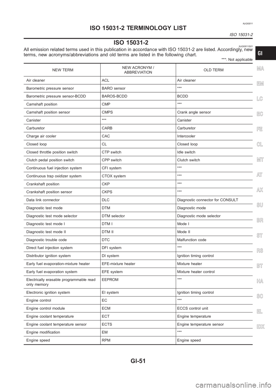
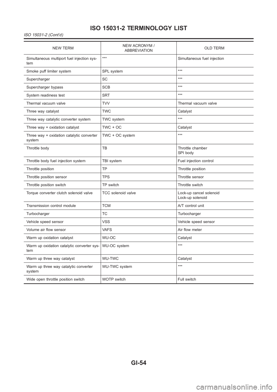
ISO 15031-2NJGI0011S01All emission related terms used in this publication in accordance with ISO15031-2 are listed. Accordingly, new
terms, new acronyms/abbreviations and old terms are listed in the following chart.
***: Not applicable
NEW TERMNEW ACRONYM /
ABBREVIATIONOLD TERM
Air cleaner ACL Air cleaner
Barometric pressure sensor BARO sensor ***
Barometric pressure sensor-BCDD BAROS-BCDD BCDD
Camshaft position CMP ***
Camshaft position sensor CMPS Crank angle sensor
Canister *** Canister
Carburetor CARB Carburetor
Charge air cooler CAC Intercooler
Closed loop CL Closed loop
Closed throttle position switch CTP switch Idle switch
Clutch pedal position switch CPP switch Clutch switch
Continuous fuel injection system CFI system ***
Continuous trap oxidizer system CTOX system ***
Crankshaft position CKP ***
Crankshaft position sensor CKPS ***
Data link connector DLC Diagnostic connector for CONSULT
Diagnostic test mode DTM Diagnostic mode
Diagnostic test mode selector DTM selector Diagnostic mode selector
Diagnostic test mode I DTM I Mode I
Diagnostic test mode II DTM II Mode II
Diagnostic trouble code DTC Malfunction code
Direct fuel injection system DFI system ***
Distributor ignition system DI system Ignition timing control
Early fuel evaporation-mixture heater EFE-mixture heater Mixture heater
Early fuel evaporation system EFE system Mixture heater control
Electrically erasable programmable read
only memoryEEPROM ***
Electronic ignition system EI system Ignition timing control
Engine control EC ***
Engine control module ECM ECCS control unit
Engine coolant temperature ECT Engine temperature
Engine coolant temperature sensor ECTS Engine temperature sensor
Engine modification EM ***
Engine speed RPM Engine speedMA
EM
LC
EC
FE
CL
MT
AT
AX
SU
BR
ST
RS
BT
HA
SC
EL
IDX
ISO 15031-2 TERMINOLOGY LIST
ISO 15031-2
GI-51
Page 56 of 3189
NEW TERMNEW ACRONYM /
ABBREVIATIONOLD TERM
Simultaneous multiport fuel injection sys-
tem*** Simultaneous fuel injection
Smoke puff limiter system SPL system ***
Supercharger SC ***
Supercharger bypass SCB ***
System readiness test SRT ***
Thermal vacuum valve TVV Thermal vacuum valve
Three way catalyst TWC Catalyst
Three way catalytic converter system TWC system ***
Three way + oxidation catalyst TWC + OC Catalyst
Three way + oxidation catalytic converter
systemTWC + OC system ***
Throttle body TB Throttle chamber
SPI body
Throttle body fuel injection system TBI system Fuel injection control
Throttle position TP Throttle position
Throttle position sensor TPS Throttle sensor
Throttle position switch TP switch Throttle switch
Torque converter clutch solenoid valve TCC solenoid valve Lock-up cancelsolenoid
Lock-up solenoid
Transmission control module TCM A/T control unit
Turbocharger TC Turbocharger
Vehicle speed sensor VSS Vehicle speed sensor
Volume air flow sensor VAFS Air flow meter
Warm up oxidation catalyst WU-OC Catalyst
Warm up oxidation catalytic converter sys-
temWU-OC system ***
Warm up three way catalyst WU-TWC Catalyst
Warm up three way catalytic converter
systemWU-TWC system ***
Wide open throttle position switch WOTP switch Full switch
ISO 15031-2 TERMINOLOGY LIST
ISO 15031-2 (Cont’d)
GI-54
Page 94 of 3189
![NISSAN ALMERA N16 2003 Electronic Repair Manual EM-16
[QG]
INTAKE MANIFOLD
INTAKE MANIFOLD
PFP:14003
Removal and InstallationEBS00LQ3
REMOVAL
WARNING:
To avoid the danger of being scalded, never drain the coolant when the engine is hot.
1. Release](/manual-img/5/57350/w960_57350-93.png "NISSAN ALMERA N16 2003 Electronic Repair Manual EM-16
[QG]
INTAKE MANIFOLD
INTAKE MANIFOLD
PFP:14003
Removal and InstallationEBS00LQ3
REMOVAL
WARNING:
To avoid the danger of being scalded, never drain the coolant when the engine is hot.
1. Release")
EM-16
[QG]
INTAKE MANIFOLD
INTAKE MANIFOLD
PFP:14003
Removal and InstallationEBS00LQ3
REMOVAL
WARNING:
To avoid the danger of being scalded, never drain the coolant when the engine is hot.
1. Release fuel pressure.
Refer to EC-34, "
FUEL PRESSURE RELEASE" (WITH EURO-OBD), EC-427, "FUEL PRESSURE
RELEASE" (WITHOUT EURO-OBD).
2. Remove air duct and air cleaner case.
Refer to EM-14, "
Removal and Installation" .
3. Disconnect harness on engine top surface, and move it aside.
4. Disconnect fuel injector/fuel tube assembly from intake manifold, and move it aside.
●It is not necessary to disconnect fuel hose.
5. Disconnect the following vacuum hoses.
6. Disconnect blow-by hose (between intake manifold collector and rocker cover).
KBIA1363E
1. Electric throttle control actuator 2. Gasket 3. Intake manifold collector
4.EVAP canister purge volume control
solenoid valve5. Vacuum hose 6. Vacuum hose
7. Hose clamp 8. Intake manifold support (front) 9. Harness bracket
10. Vacuum hose 11. Intake manifold 12. PCV hose
13. Gasket 14. Vacuum hose 15. Gasket
16. Intake manifold support (rear) 17. Harness bracket 18. Intake manifold support (engine rear)
19. Grounding wire
Page 95 of 3189
![NISSAN ALMERA N16 2003 Electronic Repair Manual INTAKE MANIFOLD
EM-17
[QG]
C
D
E
F
G
H
I
J
K
L
MA
EM
7. Loosen mounting bolts in reverse order shown in figure to
remove electric throttle control actuator.
CAUTION:
●Do not shock it.
●Do](/manual-img/5/57350/w960_57350-94.png "NISSAN ALMERA N16 2003 Electronic Repair Manual INTAKE MANIFOLD
EM-17
[QG]
C
D
E
F
G
H
I
J
K
L
MA
EM
7. Loosen mounting bolts in reverse order shown in figure to
remove electric throttle control actuator.
CAUTION:
●Do not shock it.
●Do")
INTAKE MANIFOLD
EM-17
[QG]
C
D
E
F
G
H
I
J
K
L
MA
EM
7. Loosen mounting bolts in reverse order shown in figure to
remove electric throttle control actuator.
CAUTION:
●Do not shock it.
●Do not disassembly and adjusting.
NOTE:
Remove intake manifold collector and electronic throttle control
as a single assembly, then remove electronic throttle control
itself.
8. Remove bolt on cylinder head side of intake manifold collector.
9. Loosen intake manifold collector nuts and bolts in reverse of the
order shown in the figure.
●Do not remove intake manifold collector at this stage.
10. Move harness, which is fixed on intake manifold support, with bracket.
11. Remove intake manifold supports (rear, front, engine rear).
12. Loosen nuts and bolts in reverse order shown in the figure, and
remove intake manifold from cylinder head.
13. Disconnect intake manifold collector from intake manifold, and
pull out between engine and body.
PBIC0534E
KBIA1365E
KBIA1366E
PBIC0535E
Page 96 of 3189
![NISSAN ALMERA N16 2003 Electronic Repair Manual EM-18
[QG]
INTAKE MANIFOLD
INSPECTION AFTER REMOVAL
Surface Distortion
●Using straightedge and feeler gauge, inspect surface distortion
of intake manifold collector and intake manifold surfac](/manual-img/5/57350/w960_57350-95.png "NISSAN ALMERA N16 2003 Electronic Repair Manual EM-18
[QG]
INTAKE MANIFOLD
INSPECTION AFTER REMOVAL
Surface Distortion
●Using straightedge and feeler gauge, inspect surface distortion
of intake manifold collector and intake manifold surfac")
EM-18
[QG]
INTAKE MANIFOLD
INSPECTION AFTER REMOVAL
Surface Distortion
●Using straightedge and feeler gauge, inspect surface distortion
of intake manifold collector and intake manifold surface.
INSTALLATION
●Install in the reverse order of removal paying attention to the following.
Tightening Intake Manifold
●Temporarily attach before installing intake manifold collector.
●Tighten in numerical order as shown in the figure.
Tightening Intake Manifold Collector
●Temporarily attach before installing intake manifold.
●Tighten in numerical order as shown in the figure.
Installation of Electric Throttle Control Actuator
●Tighten mounting bolts for electric throttle control actuator in
numerical order shown in figure.
CAUTION:
When electric throttle control actuator is replaced, perform
idle air volume learning.
●Refer to BASIC SERVICE PROCEDURE, EC-31, "Idle Air Vol-
ume Learning" (WITH EURO-OBD), EC-425, "Idle Air Volume
Learning" (WITHOUT EURO-OBD). Limit : 0.1 mm (0.004 in)
PBIC0536E
PBIC0535E
KBIA1366E
: 17.7 - 21.6 N·m (1.8 - 2.2 kg-m, 13 - 15 ft-lb)
PBIC0534E
Page 182 of 3189
![NISSAN ALMERA N16 2003 Electronic Repair Manual EM-104
[QG]
SERVICE DATA AND SPECIFICATIONS (SDS)
CONNECTING ROD BEARING
Standard Size
Unit: mm (in)
Undersize
Unit: mm (in)
Bearing Clearance
Unit: mm (in)
MISCELLANEOUS COMPONENTS
Unit: mm (in)
*: T](/manual-img/5/57350/w960_57350-181.png "NISSAN ALMERA N16 2003 Electronic Repair Manual EM-104
[QG]
SERVICE DATA AND SPECIFICATIONS (SDS)
CONNECTING ROD BEARING
Standard Size
Unit: mm (in)
Undersize
Unit: mm (in)
Bearing Clearance
Unit: mm (in)
MISCELLANEOUS COMPONENTS
Unit: mm (in)
*: T")
EM-104
[QG]
SERVICE DATA AND SPECIFICATIONS (SDS)
CONNECTING ROD BEARING
Standard Size
Unit: mm (in)
Undersize
Unit: mm (in)
Bearing Clearance
Unit: mm (in)
MISCELLANEOUS COMPONENTS
Unit: mm (in)
*: Total indicator reading
Tightening TorqueEBS00LQQ
*1: Parts to be tightened in particular orders.
1)-: Order of tightening when tightening two or more times separately.
Unit: N·m (kg-m, ft-lb) / Unit: N·m (kg-m, in-lb)*2
Grade No. Thickness Identification color or number
0 1.503 - 1.506 (0.0592 - 0.0593) Block
1 1.506 - 1.509 (0.0593 - 0.0594) Red
2 1.509 - 1.512 (0.0594 - 0.0595) Green
Grade No. Thickness Identification color or number
0.08 (0.0031) 1.542 - 1.546 (0.0607 - 0.0609) —
0.12 (0.0047) 1.562 - 1.566 (0.0615 - 0.0617) —
0.25 (0.0098) 1.627 - 1.631 (0.0641 - 0.0642) —
Connecting rod bearing clear-
anceStandard 0.014 - 0.039 (0.0006 - 0.0015)
Limit 0.1 (0.004)
Flywheel runout [TIR*] Less than 0.1 (0.004)
Camshaft sprocket runout [TIR*] Less than 0.15 (0.0059)
Mass air flow sensor
8.4 - 10.8 (0.9 - 1.1, 75 - 95)*2
Resonator
3.8 - 4.5 (0.39 - 0.45, 34 - 39)*2
Air cleaner case lower
3.8 - 4.5 (0.39 - 0.46, 34 - 39)*2
Intake manifold16.7 - 23.5 (1.7 - 2.4, 13 - 17)
Intake manifold collector
7.0 - 9.5 (0.71 - 0.97, 62 - 84)*
2
Intake manifold support 16.7 - 23.5 (1.7 - 2.4, 13 - 17)
Electric throttle control actuator 17.7 - 21.6 (1.8 - 2.2, 13 - 15)
Exhaust manifold25.5 - 29.4 (2.6 - 2.9, 19 - 21)
Exhaust manifold cover
6.3 - 8.3 (0.64 - 0.85, 56 - 73)*
2
Heated oxygen sensor 58.8 - 78.4 (6.0 - 7.9, 44 - 57)
Ground nut79.4 (8.1, 59)
Oil pan
6.28 - 8.34 (0.64 - 0.85, 56 - 73)*
2
Oil pan drain plug29.4 - 39.2 ( 3.0 - 3.9, 22 - 28)
Oil strainer
6.28 - 8.34 (0.64 - 0.85, 56 - 73)*
2
Ignition coil
3.8 - 5.0 (0.38 - 0.51, 33 - 44)*2
Spark plug19.6 - 29.4 (2.0 - 3.0, 15 - 21)
*1 Fuel tube1) 11.8 - 13.8 (1.2 - 1.4, 9 - 10 )
2) 17 - 23 (1.7 - 2.4, 13 - 17)
Rocker cover
6.9 - 9.5 (0.70 - 0.97, 61 - 84)*
2
Page 331 of 3189
EC-1
ENGINE CONTROL SYSTEM
B ENGINE
CONTENTS
C
D
E
F
G
H
I
J
K
L
M
SECTION
A
EC
ENGINE CONTROL SYSTEM
QG (WITH EURO-OBD)
INDEX FOR DTC ...................................................... 10
Alphabetical Index .................................................. 10
DTC No. Index ....................................................... 12
PRECAUTIONS ........................................................ 15
Precautions for Supplemental Restraint System
(SRS) “AIR BAG” and “SEAT BELT PRE-TEN-
SIONER” ................................................................ 15
On Board Diagnostic (OBD) System of Engine and
A/T .......................................................................... 15
Precaution .............................................................. 15
Wiring Diagrams and Trouble Diagnosis ................ 18
PREPARATION ......................................................... 19
Special Service Tools ............................................. 19
Commercial Service Tools ...................................... 19
ENGINE CONTROL SYSTEM .................................. 21
System Diagram ..................................................... 21
Vacuum Hose Drawing ........................................... 22
System Chart ......................................................... 23
Multiport Fuel Injection (MFI) System .................... 23
Electronic Ignition (EI) System ............................... 25
Air Conditioning Cut Control ................................... 26
Fuel Cut Control (at No Load and High Engine
Speed) .................................................................... 27
CAN Communication .............................................. 27
BASIC SERVICE PROCEDURE .............................. 30
Idle Speed and Ignition Timing Check .................... 30
Accelerator Pedal Released Position Learning ...... 31
Throttle Valve Closed Position Learning ................ 31
Idle Air Volume Learning ........................................ 31
Fuel Pressure Check .............................................. 34
ON BOARD DIAGNOSTIC (OBD) SYSTEM ............ 36
Introduction ............................................................ 36
Two Trip Detection Logic ........................................ 36
Emission-related Diagnostic Information ................ 37
NATS (Nissan Anti-theft System) ........................... 49
Malfunction Indicator (MI) ....................................... 49
OBD System Operation Chart ................................ 52
TROUBLE DIAGNOSIS ............................................ 58
Trouble Diagnosis Introduction ............................... 58DTC Inspection Priority Chart ................................. 62
Fail-safe Chart ........................................................ 63
Basic Inspection ..................................................... 65
Symptom Matrix Chart ............................................ 70
Engine Control Component Parts Location ............ 74
Circuit Diagram ....................................................... 78
ECM Harness Connector Terminal Layout ............. 80
ECM Terminals and Reference Value ..................
... 80
CONSULT-II Function ............................................. 87
Generic Scan Tool (GST) Function ......................... 97
CONSULT-II Reference Value in Data Monitor Mode
... 99
Major Sensor Reference Graph in Data Monitor
Mode .....................................................................102
TROUBLE DIAGNOSIS - SPECIFICATION VALUE .105
Description ............................................................105
Testing Condition ..................................................105
Inspection Procedure ............................................105
Diagnostic Procedure ...........................................106
TROUBLE DIAGNOSIS FOR INTERMITTENT INCI-
DENT .......................................................................109
Description ............................................................109
Diagnostic Procedure ...........................................109
POWER SUPPLY CIRCUIT FOR ECM ...................110
Wiring Diagram .....................................................110
Diagnostic Procedure ............................................111
Component Inspection ..........................................115
DTC U1000, U1001 CAN COMMUNICATION LINE .116
Description ............................................................116
On Board Diagnosis Logic ....................................116
DTC Confirmation Procedure ...............................116
Wiring Diagram .....................................................117
Diagnostic Procedure ...........................................118
DTC P0011 IVT CONTROL .....................................119
Description ............................................................119
CONSULT-II Reference Value in Data Monitor Mode
.119
On Board Diagnosis Logic ....................................120
DTC Confirmation Procedure ...............................120
Diagnostic Procedure ...........................................121