2003 NISSAN ALMERA N16 Blower motor
[x] Cancel search: Blower motorPage 2069 of 3189
TROUBLE DIAGNOSIS
ATC-89
C
D
E
F
G
H
I
K
L
MA
B
AT C
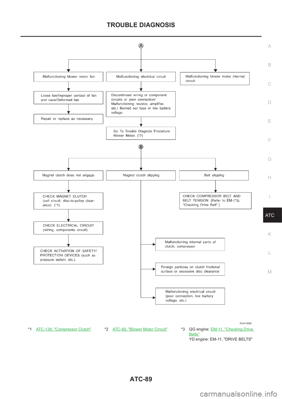
*1ATC-138, "Compressor Clutch"*2AT C - 6 9 , "Blower Motor Circuit"*3 QG engine: EM-11, "Checking Drive
Belts"
YD engine: EM-11, "DRIVE BELTS"
RJIA1595E
Page 2076 of 3189
ATC-96
TROUBLE DIAGNOSIS
*7AT C - 5 7 , "LAN System Circuit"*8ATC-69, "Blower Motor Circuit"*9AT C - 6 3 , "Air Mix Door Motor Circuit"
*10 QG engine (With EURO–OBD): EC-
144, "DTC P0117, P0118 ECT SEN-
SOR"
QG engine (Without EURO–OBD):
EC-501, "
DTC P0117, P0118 ECT
SENSOR"
YD engine: EC-84, "P0115 COOL-
ANT TEMP SEN" *11 QG engine: LC-17, "Changing
Engine Coolant"
YD engine: LC-43, "Changing
Engine Coolant" *12 QG engine: LC-17, "Changing
Engine Coolant"
YD engine: LC-43, "Changing
Engine Coolant"
Page 2099 of 3189
BLOWER UNIT
ATC-119
C
D
E
F
G
H
I
K
L
MA
B
AT C
BLOWER UNITPFP:27200
Removal and InstallationEJS00206
REMOVAL
1. Remove the glove box assembly.
2. Remove the glove box cover and instrument lower assist panel.
3. Remove the ECM with ECM bracket.
4. Remove the blower unit fixing bolt and screw.
5. Disconnect the blower motor connector, intake door motor con-
nector and auto amp. connector.
6. Remove the harness fixing clip.
7. Move the blower unit downwards.
CAUTION:
Slide the blower unit toward the passenger side, remove loca-
tion pins (2 pieces), then move it downwards.
8. Remove the blower unit.
INSTALLATION
CAUTION:
●Make sure the location pins (2 pieces) are securely installed.
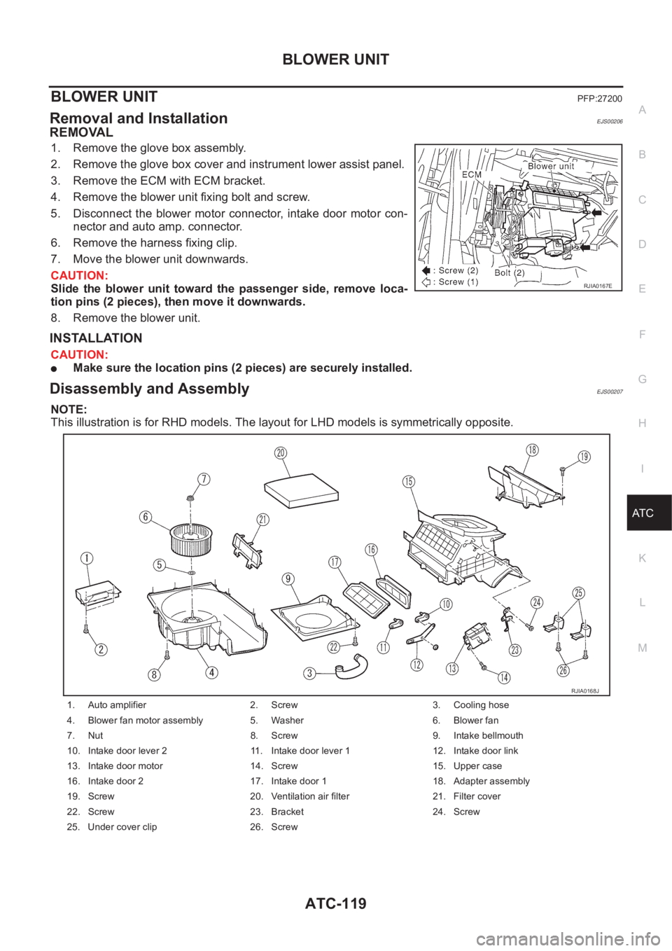
Disassembly and AssemblyEJS00207
NOTE:
This illustration is for RHD models. The layout for LHD models is symmetrically opposite.
RJIA0167E
1. Auto amplifier 2. Screw 3. Cooling hose
4. Blower fan motor assembly 5. Washer 6. Blower fan
7. Nut 8. Screw 9. Intake bellmouth
10. Intake door lever 2 11. Intake door lever 1 12. Intake door link
13. Intake door motor 14. Screw 15. Upper case
16. Intake door 2 17. Intake door 1 18. Adapter assembly
19. Screw 20. Ventilation air filter 21. Filter cover
22. Screw 23. Bracket 24. Screw
25. Under cover clip 26. Screw
RJIA0168J
Page 2100 of 3189
ATC-120
BLOWER MOTOR
BLOWER MOTOR
PFP:27226
Removal and InstallationEJS00208
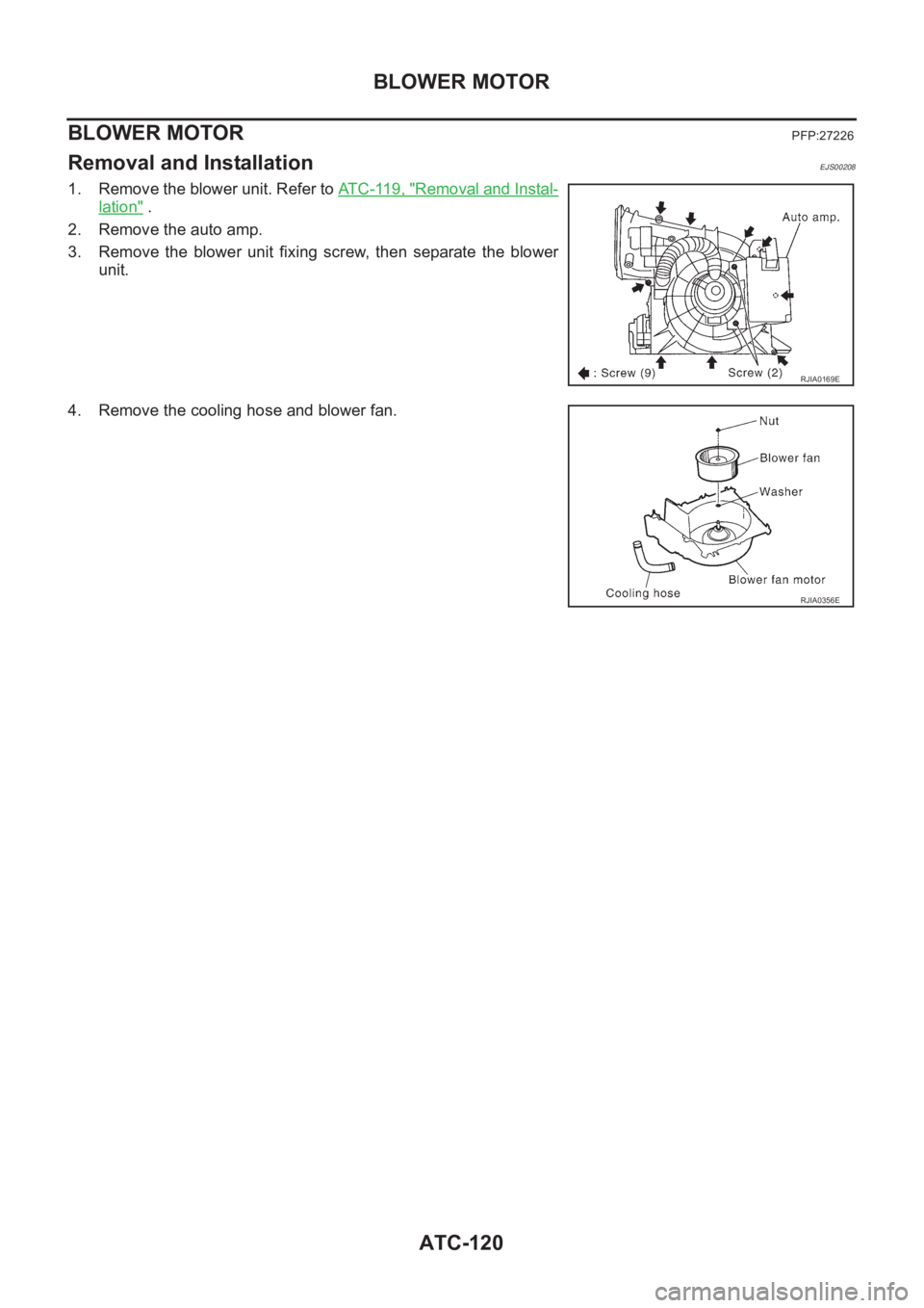
1. Remove the blower unit. Refer to AT C - 11 9 , "Removal and Instal-
lation" .
2. Remove the auto amp.
3. Remove the blower unit fixing screw, then separate the blower
unit.
4. Remove the cooling hose and blower fan.
RJIA0169E
RJIA0356E
Page 2101 of 3189
INTAKE DOOR MOTOR
ATC-121
C
D
E
F
G
H
I
K
L
MA
B
AT C
INTAKE DOOR MOTORPFP:27730
Removal and InstallationEJS00209
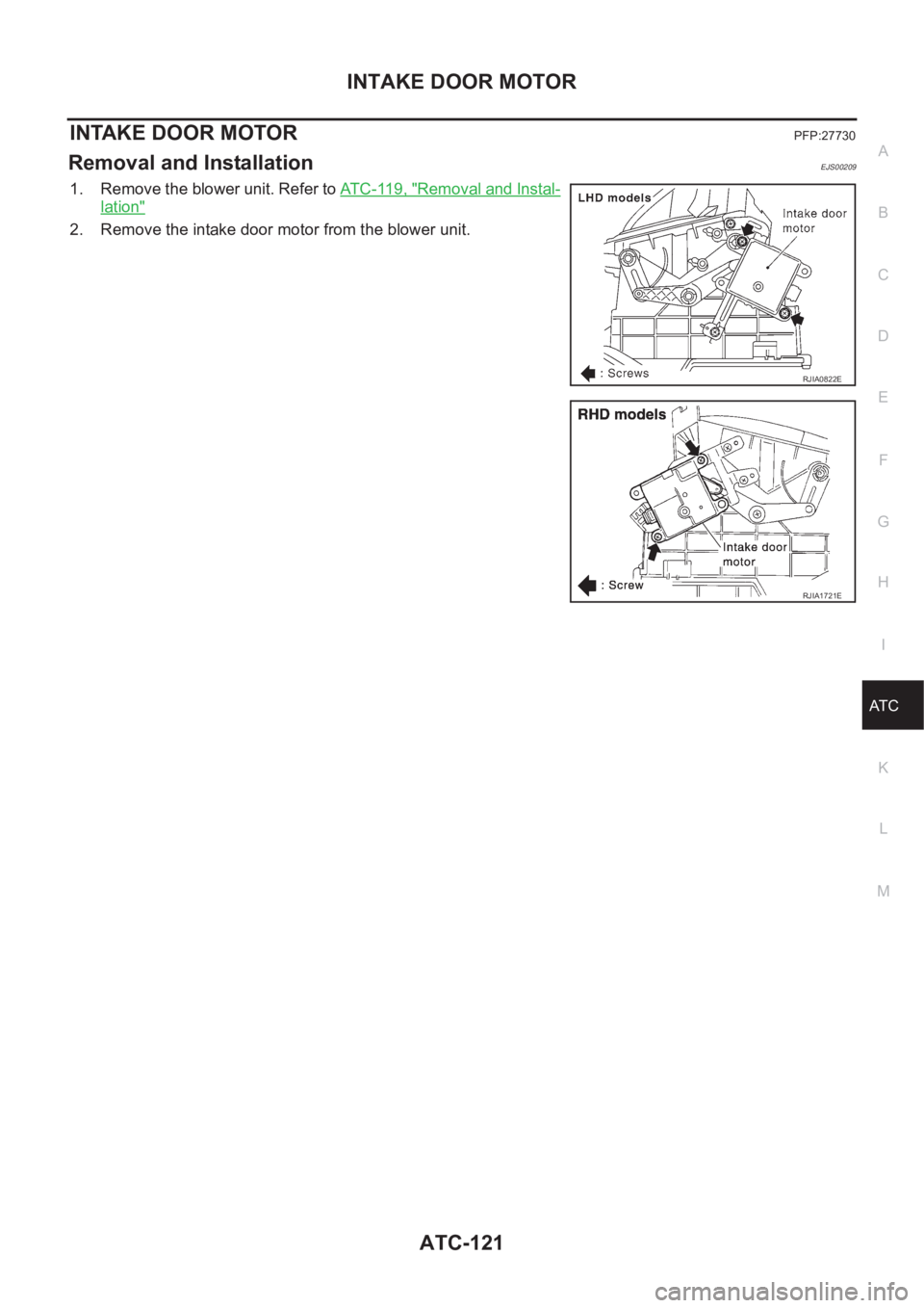
1. Remove the blower unit. Refer to AT C - 11 9 , "Removal and Instal-
lation"
2. Remove the intake door motor from the blower unit.
RJIA0822E
RJIA1721E
Page 2937 of 3189
HEATER &
MANUAL AIR CONDITIONER
SECTION
HA
CONTENTS
MANUAL
PRECAUTIONS<0011001100110011001100110011001100110011001100110011001100110011001100110011001100110011001100110011001100110011001100110011001100110011001100110011001100110011001100110011001100110011001100110011001100
11001100110011001100110011001100110011001100110011[2
Supplemental Restraint System (SRS)″AIR
BAG″and″SEAT BELT PRE-TENSIONER″...............2
Precautions for Working with HFC-134a (R-134a) .....2
General Refrigerant Precautions .................................2
Precautions for Refrigerant Connection ......................3
Precautions for Servicing Compressor ........................5
Precautions for Service Equipment .............................6
Wiring Diagrams and Trouble Diagnosis .....................8
PREPARATION<0011001100110011001100110011001100110011001100110011001100110011001100110011001100110011001100110011001100110011001100110011001100110011001100110011001100110011001100110011001100110011001100110011001100
11001100110011001100110011001100110011001100110011[9
Special Service Tools ..................................................9
HFC-134a (R-134a) Service Tools and
Equipment <0011001100110011001100110011001100110011001100110011001100110011001100110011001100110011001100110011001100110011001100110011001100110011001100110011001100110011001100110011001100110011001100110011001100
11001100110011[............10
DESCRIPTION<0011001100110011001100110011001100110011001100110011001100110011001100110011001100110011001100110011001100110011001100110011001100110011001100110011001100110011001100110011001100110011001100110011001100
11001100110011001100110011001100110011001100110011[12
Refrigeration System .................................................12
CSV613 Variable Displacement Compressor............13
Component Layout ....................................................17
Control Operation ......................................................18
Discharge Air Flow.....................................................19
System Description ....................................................20
TROUBLE DIAGNOSES................................................21
Component Location..................................................21
Wiring Diagram - Heater............................................23
Circuit Diagram - Air Conditioner...............................24
Wiring Diagram - A/C, M - .........................................25
How to Perform Trouble Diagnoses for Quick
and Accurate Repair ..................................................34Operational Check .....................................................35
Intake Door <0011001100110011001100110011001100110011001100110011001100110011001100110011001100110011001100110011001100110011001100110011001100110011001100110011001100110011001100110011001100110011001100110011001100
1100110011[...........37
Mode Door <0011001100110011001100110011001100110011001100110011001100110011001100110011001100110011001100110011001100110011001100110011001100110011001100110011001100110011001100110011001100110011001100110011001100
110011001100110011[..........41
Air Mix Door <0011001100110011001100110011001100110011001100110011001100110011001100110011001100110011001100110011001100110011001100110011001100110011001100110011001100110011001100110011001100110011001100110011001100
1100110011[..........43
Blower Motor<0011001100110011001100110011001100110011001100110011001100110011001100110011001100110011001100110011001100110011001100110011001100110011001100110011001100110011001100110011001100110011001100110011001100
110011[..........45
Magnet Clutch<0011001100110011001100110011001100110011001100110011001100110011001100110011001100110011001100110011001100110011001100110011001100110011001100110011001100110011001100110011001100110011001100110011001100
11[.........52
Insufficient Cooling ....................................................66
Insufficient Heating ....................................................75
Noise <0011001100110011001100110011001100110011001100110011001100110011001100110011001100110011001100110011001100110011001100110011001100110011001100110011001100110011001100110011001100110011001100110011001100
110011001100110011001100110011[................76
SERVICE PROCEDURE................................................77
HFC-134a (R-134a) Service Procedure ....................77
Maintenance of Lubricant Quantity in
Compressor <0011001100110011001100110011001100110011001100110011001100110011001100110011001100110011001100110011001100110011001100110011001100110011001100110011001100110011001100110011001100110011001100110011001100
1100110011[..........79
Compressor <0011001100110011001100110011001100110011001100110011001100110011001100110011001100110011001100110011001100110011001100110011001100110011001100110011001100110011001100110011001100110011001100110011001100
1100110011[..........82
Compressor Clutch - CSV613 (CALSONIC
make) <0011001100110011001100110011001100110011001100110011001100110011001100110011001100110011001100110011001100110011001100110011001100110011001100110011001100110011001100110011001100110011001100110011001100
110011001100110011001100110011[...............83
Heater & Cooling Unit (Heater Core) ........................87
A/C Evaporator ..........................................................87
Blower Unit <0011001100110011001100110011001100110011001100110011001100110011001100110011001100110011001100110011001100110011001100110011001100110011001100110011001100110011001100110011001100110011001100110011001100
1100110011[...........89
Refrigerant Lines .......................................................90
Belt <0011001100110011001100110011001100110011001100110011001100110011001100110011001100110011001100110011001100110011001100110011001100110011001100110011001100110011001100110011001100110011001100110011001100
1100110011001100110011001100110011[..................94
Ventilation Air Filter ....................................................95
SERVICE DATA AND SPECIFICATIONS (SDS).........96
Compressor <0011001100110011001100110011001100110011001100110011001100110011001100110011001100110011001100110011001100110011001100110011001100110011001100110011001100110011001100110011001100110011001100110011001100
1100110011[..........96
Lubricant <0011001100110011001100110011001100110011001100110011001100110011001100110011001100110011001100110011001100110011001100110011001100110011001100110011001100110011001100110011001100110011001100110011001100
11001100110011[..............96
Refrigerant <0011001100110011001100110011001100110011001100110011001100110011001100110011001100110011001100110011001100110011001100110011001100110011001100110011001100110011001100110011001100110011001100110011001100
110011[.............96
Engine Idling Speed (When A/C is On).....................96
Belt Tension <0011001100110011001100110011001100110011001100110011001100110011001100110011001100110011001100110011001100110011001100110011001100110011001100110011001100110011001100110011001100110011001100110011001100
110011[...........96
GI
MA
EM
LC
EC
FE
CL
MT
AT
AX
SU
BR
ST
RS
BT
SC
EL
IDX
Page 2970 of 3189
How to Perform Trouble Diagnoses for Quick
and Accurate Repair
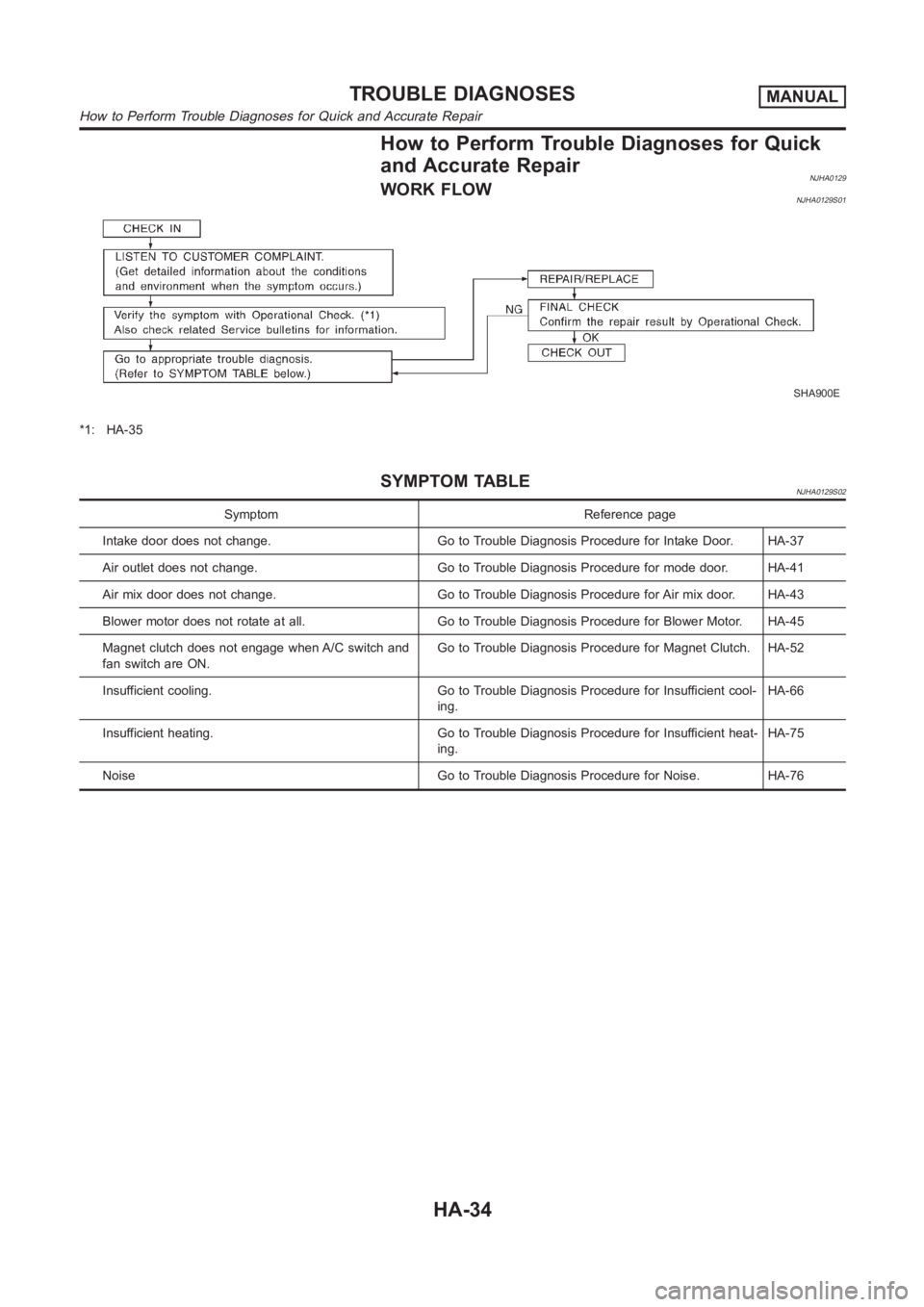
NJHA0129WORK FLOWNJHA0129S01
SHA900E
*1: HA-35
SYMPTOM TABLENJHA0129S02
Symptom Reference page
Intake door does not change. Go to Trouble Diagnosis Procedure for Intake Door. HA-37
Air outlet does not change. Go to Trouble Diagnosis Procedure for mode door. HA-41
Air mix door does not change. Go to Trouble Diagnosis Procedure for Air mix door. HA-43
Blower motor does not rotate at all. Go to Trouble Diagnosis Procedure for Blower Motor. HA-45
Magnet clutch does not engage when A/C switch and
fan switch are ON.Go to Trouble Diagnosis Procedure for Magnet Clutch. HA-52
Insufficient cooling. Go to Trouble Diagnosis Procedure for Insufficient cool-
ing.HA-66
Insufficient heating. Go to Trouble Diagnosis Procedure for Insufficientheat-
ing.HA-75
Noise Go to Trouble Diagnosis Procedure for Noise. HA-76
TROUBLE DIAGNOSESMANUAL
How to Perform Trouble Diagnoses for Quick and Accurate Repair
HA-34
Page 2971 of 3189
Operational Check=NJHA0130The purpose of the operational check is to confirm that the system
operates properly.
CONDITIONS:NJHA0130S01Engine running and at usual operating temperature.
NHA374
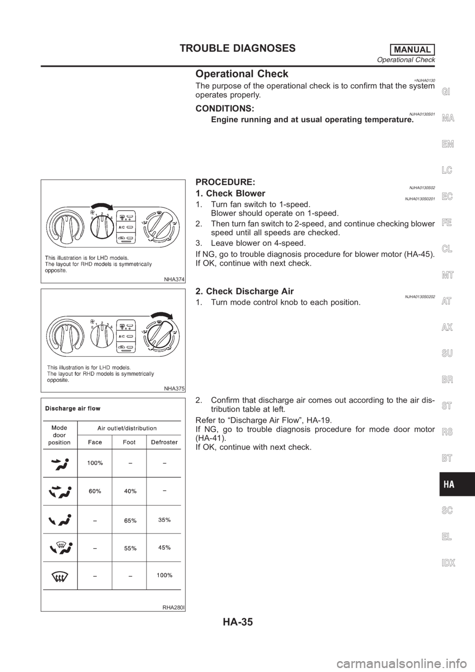
PROCEDURE:NJHA0130S021. Check BlowerNJHA0130S02011. Turn fan switch to 1-speed.
Blower should operate on 1-speed.
2. Then turn fan switch to 2-speed, and continue checking blower
speed until all speeds are checked.
3. Leave blower on 4-speed.
If NG, go to trouble diagnosis procedure for blower motor (HA-45).
If OK, continue with next check.
NHA375
2. Check Discharge AirNJHA0130S02021. Turn mode control knob to each position.
RHA280I
2. Confirm that discharge air comes out according to the air dis-
tribution table at left.
Refer to “Discharge Air Flow”, HA-19.
If NG, go to trouble diagnosis procedure for mode door motor
(HA-41).
If OK, continue with next check.
GI
MA
EM
LC
EC
FE
CL
MT
AT
AX
SU
BR
ST
RS
BT
SC
EL
IDX
TROUBLE DIAGNOSESMANUAL
Operational Check
HA-35