Page 2577 of 3189

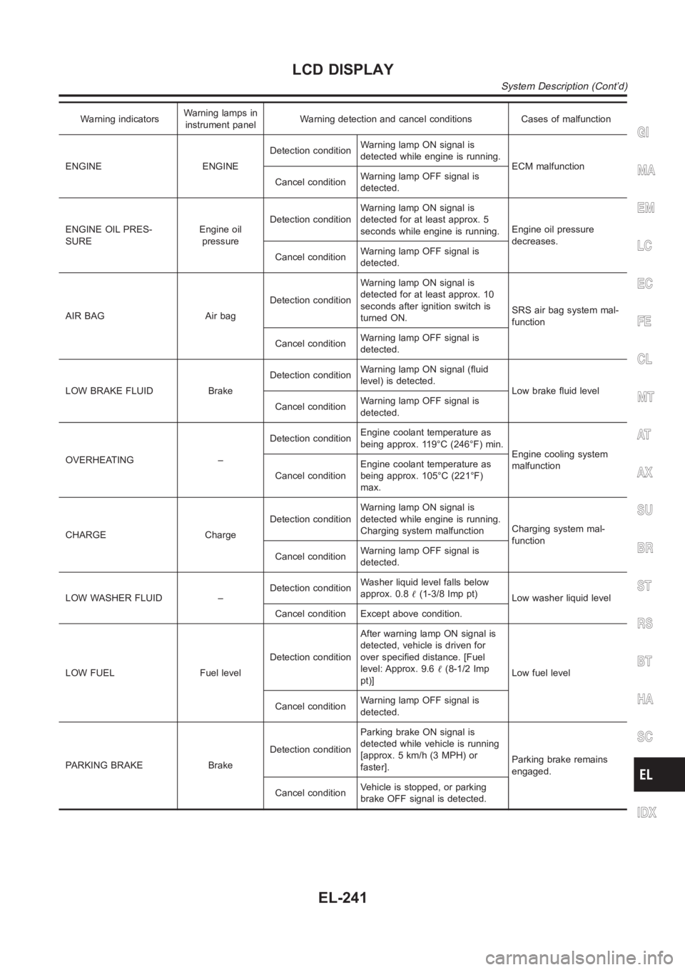
Warning indicatorsWarning lamps in
instrument panelWarning detection and cancel conditions Cases of malfunction
ENGINE ENGINEDetection conditionWarning lamp ON signal is
detected while engine is running.
ECM malfunction
Cancel conditionWarning lamp OFF signal is
detected.
ENGINE OIL PRES-
SUREEngine oil
pressureDetection conditionWarning lamp ON signal is
detected for at least approx. 5
seconds while engine is running.Engine oil pressure
decreases.
Cancel conditionWarning lamp OFF signal is
detected.
AIR BAG Air bagDetection conditionWarning lamp ON signal is
detected for at least approx. 10
seconds after ignition switch is
turned ON.SRS air bag system mal-
function
Cancel conditionWarning lamp OFF signal is
detected.
LOW BRAKE FLUID BrakeDetection conditionWarning lamp ON signal (fluid
level) is detected.
Low brake fluid level
Cancel conditionWarning lamp OFF signal is
detected.
OVERHEATING –Detection conditionEngine coolant temperature as
being approx. 119°C (246°F) min.
Engine cooling system
malfunction
Cancel conditionEngine coolant temperature as
being approx. 105°C (221°F)
max.
CHARGE ChargeDetection conditionWarning lamp ON signal is
detected while engine is running.
Charging system malfunctionCharging system mal-
function
Cancel conditionWarning lamp OFF signal is
detected.
LOW WASHER FLUID –Detection conditionWasher liquid level falls below
approx. 0.8�(1-3/8 Imp pt)
Low washer liquid level
Cancel condition Except above condition.
LOW FUEL Fuel levelDetection conditionAfter warning lamp ON signal is
detected, vehicle is driven for
over specified distance. [Fuel
level: Approx. 9.6�(8-1/2 Imp
pt)]Low fuel level
Cancel conditionWarning lamp OFF signal is
detected.
PARKING BRAKE BrakeDetection conditionParking brake ON signal is
detected while vehicle is running
[approx. 5 km/h (3 MPH) or
faster].Parking brake remains
engaged.
Cancel conditionVehicle is stopped, or parking
brake OFF signal is detected.
GI
MA
EM
LC
EC
FE
CL
MT
AT
AX
SU
BR
ST
RS
BT
HA
SC
IDX
LCD DISPLAY
System Description (Cont’d)
EL-241
Page 2578 of 3189
![NISSAN ALMERA N16 2003 Electronic Repair Manual Warning indicatorsWarning lamps in
instrument panelWarning detection and cancel conditions Cases of malfunction
DOOR OPEN DoorDetection conditionVehicle is running [approx. 5
km/h (3 MPH) or faster] a NISSAN ALMERA N16 2003 Electronic Repair Manual Warning indicatorsWarning lamps in
instrument panelWarning detection and cancel conditions Cases of malfunction
DOOR OPEN DoorDetection conditionVehicle is running [approx. 5
km/h (3 MPH) or faster] a](/manual-img/5/57350/w960_57350-2577.png)
Warning indicatorsWarning lamps in
instrument panelWarning detection and cancel conditions Cases of malfunction
DOOR OPEN DoorDetection conditionVehicle is running [approx. 5
km/h (3 MPH) or faster] and door
ajar of any of the doors is
detected.Doorisopen
Cancel conditionVehicle is stopped and all the
doors lock.
ABS ABSDetection conditionWarning lamp ON signal is
detected when engine is running.
ABS control system mal-
function
Cancel conditionWarning lamp OFF signal is
detected.
ESP ELECTRONIC
CONTROL SYSTEMESPDetection conditionWarning lamp ON signal is
detected when engine is running.
ESP system malfunction
Cancel conditionWarning lamp OFF signal is
detected.
CVT ELECTRONIC
CONTROL SYSTEMCVTDetection conditionWarning lamp ON signal is
detected after ignition switch is
turned ON.
TCM system malfunction
Cancel conditionWarning lamp OFF signal is
detected.
CRUISE CONTROL
SYSTEMCRUISEDetection conditionWarning lamp ON signal is
detected after ignition switch is
turned ON.
ICC system malfunction
Cancel conditionWarning lamp OFF signal is
detected.
Precautions for Display Unit ReplacementNJEL0572Record the following memorized contents before replacing the control unit.
Preset frequency
Area for indicating station, selection of overlapped stations
Program status
Volume balance memory set values
Equalizer memory set values
Brightness of light when ON/OFF
Dimming switching
Display color switching
Replace the display unit after disconnecting both battery cables.
Component Parts and Harness Connector and
Harness Connector Location
NJEL0573For details, refer to “ELECTRICAL UNIT LOCATION” (EL-543) and “HARNESS LAYOUT” (EL-550).
LCD DISPLAY
System Description (Cont’d)
EL-242
Page 2579 of 3189
Wiring Diagram — COMM —NJEL0574
YEL738D
GI
MA
EM
LC
EC
FE
CL
MT
AT
AX
SU
BR
ST
RS
BT
HA
SC
IDX
LCD DISPLAY
Wiring Diagram — COMM —
EL-243
Page 2580 of 3189
YEL739D
LCD DISPLAY
Wiring Diagram — COMM — (Cont’d)
EL-244
Page 2581 of 3189
Terminals and Reference Value for Display UnitNJEL0575Refer to EL-162.
Terminals and Reference Value for AV and
NAVI Control Unit
NJEL0576Refer to EL-450.
Terminals and Reference Value for
Multifunction Switch
NJEL0577Refer to EL-456.
Trouble DiagnosesNJEL0578Refer to EL-457, “Self-Diagnosis Function”.
GI
MA
EM
LC
EC
FE
CL
MT
AT
AX
SU
BR
ST
RS
BT
HA
SC
IDX
LCD DISPLAY
Terminals and Reference Value for Display Unit
EL-245
Page 2707 of 3189

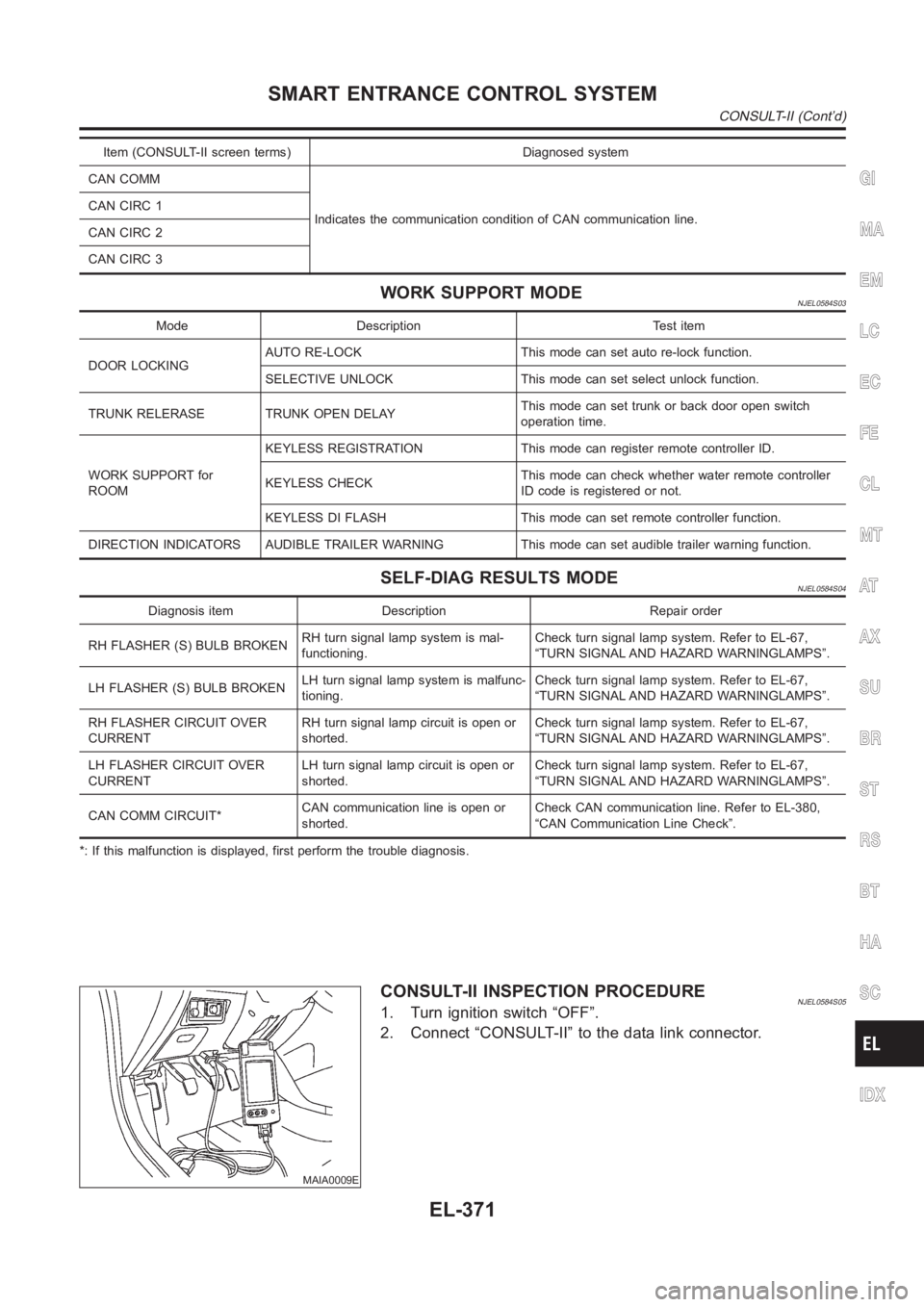
Item (CONSULT-II screen terms) Diagnosed system
CAN COMM
Indicates the communication condition of CAN communication line. CANCIRC1
CANCIRC2
CANCIRC3
WORK SUPPORT MODENJEL0584S03
Mode Description Test item
DOOR LOCKINGAUTO RE-LOCK This mode can set auto re-lock function.
SELECTIVE UNLOCK This mode can set select unlock function.
TRUNK RELERASE TRUNK OPEN DELAYThis mode can set trunk or back door open switch
operation time.
WORK SUPPORT for
ROOMKEYLESS REGISTRATION This mode can register remote controller ID.
KEYLESS CHECKThis mode can check whether water remote controller
ID code is registered or not.
KEYLESS DI FLASH This mode can set remote controller function.
DIRECTION INDICATORS AUDIBLE TRAILER WARNING This mode can set audible trailer warning function.
SELF-DIAG RESULTS MODENJEL0584S04
Diagnosis item Description Repair order
RH FLASHER (S) BULB BROKENRH turn signal lamp system is mal-
functioning.Check turn signal lamp system. Refer to EL-67,
“TURN SIGNAL AND HAZARD WARNINGLAMPS”.
LH FLASHER (S) BULB BROKENLH turn signal lamp system is malfunc-
tioning.Check turn signal lamp system. Refer to EL-67,
“TURN SIGNAL AND HAZARD WARNINGLAMPS”.
RH FLASHER CIRCUIT OVER
CURRENTRH turn signal lamp circuit is open or
shorted.Check turn signal lamp system. Refer to EL-67,
“TURN SIGNAL AND HAZARD WARNINGLAMPS”.
LH FLASHER CIRCUIT OVER
CURRENTLH turn signal lamp circuit is open or
shorted.Check turn signal lamp system. Refer to EL-67,
“TURN SIGNAL AND HAZARD WARNINGLAMPS”.
CAN COMM CIRCUIT*CAN communication line is open or
shorted.Check CAN communication line. Refer to EL-380,
“CAN Communication Line Check”.
*: If this malfunction is displayed, first perform the trouble diagnosis.
MAIA0009E
CONSULT-II INSPECTION PROCEDURENJEL0584S051. Turn ignition switch “OFF”.
2. Connect “CONSULT-II” to the data link connector.
GI
MA
EM
LC
EC
FE
CL
MT
AT
AX
SU
BR
ST
RS
BT
HA
SC
IDX
SMART ENTRANCE CONTROL SYSTEM
CONSULT-II (Cont’d)
EL-371
Page 2714 of 3189

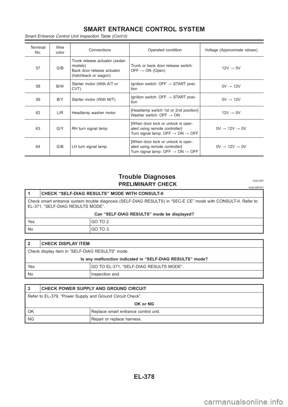
Terminal
No.Wire
colorConnections Operated condition Voltage (Approximate values)
57 G/BTrunk release actuator (sedan
models)
Back door release actuator
(hatchback or wagon)Trunk or back door release switch:
OFF,ON (Open)12V,0V
58 B/WStarter motor (With A/T or
CVT)Ignition switch: OFF,START posi-
tion0V,12V
59 B/Y Starter motor (With M/T)Ignition switch: OFF,START posi-
tion0V,12V
62 L/R Headlamp washer motor[Headlamp switch 1st or 2nd position]
Washer switch: OFF,ON12V,0V
63 G/Y RH turn signal lamp[When door lock or unlock is oper-
ated using remote controller]
Turn signal lamp: OFF,ON,OFF0V,12V,0V
64 G/B LH turn signal lamp[When door lock or unlock is oper-
ated using remote controller]
Turn signal lamp: OFF,ON,OFF0V,12V,0V
Trouble DiagnosesNJEL0587PRELIMINARY CHECKNJEL0587S01
1 CHECK “SELF-DIAG RESULTS” MODE WITH CONSULT-II
Check smart entrance system trouble diagnosis (SELF-DIAG RESULTS) in “SEC-E CE” mode with CONSULT-II. Refer to
EL-371, “SELF-DIAG RESULTS MODE”.
Can “SELF-DIAG RESULTS” mode be displayed?
Ye s G O T O 2 .
No GO TO 3.
2 CHECK DISPLAY ITEM
Check display item in “SELF-DIAG RESULTS” mode.
Is any malfunction indicated in “SELF-DIAG RESULTS” mode?
Yes GO TO EL-371, “SELF-DIAG RESULTS MODE”.
No Inspection end.
3 CHECK POWER SUPPLY AND GROUND CIRCUIT
Refer to EL-379, “Power Supply and Ground Circuit Check”.
OK or NG
OK Replace smart entrance control unit.
NG Repair or replace harness.
SMART ENTRANCE CONTROL SYSTEM
Smart Entrance Control Unit Inspection Table (Cont’d)
EL-378
Page 2730 of 3189

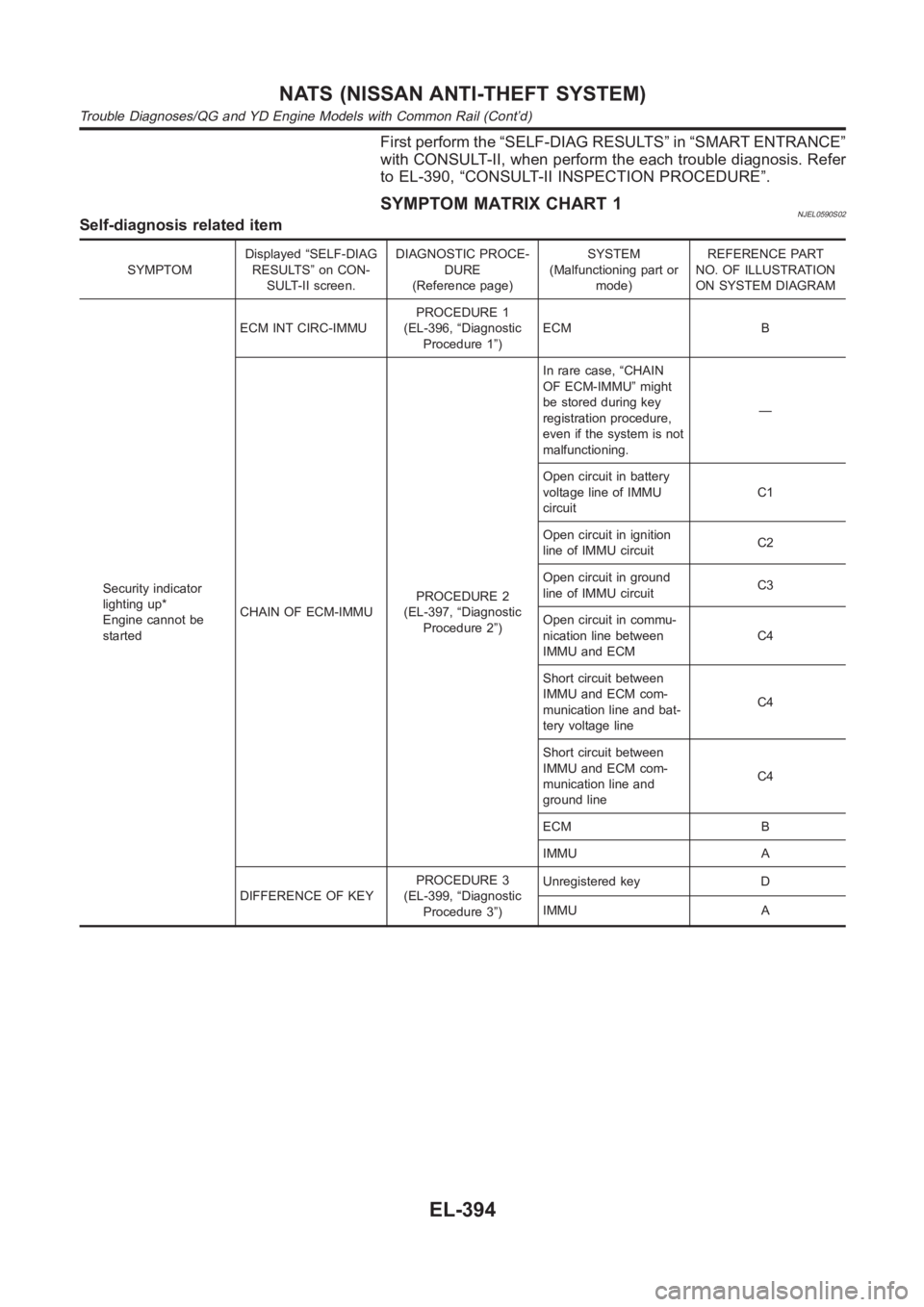
First perform the “SELF-DIAG RESULTS” in “SMART ENTRANCE”
with CONSULT-II, when perform the each trouble diagnosis. Refer
to EL-390, “CONSULT-II INSPECTION PROCEDURE”.
SYMPTOM MATRIX CHART 1NJEL0590S02Self-diagnosis related item
SYMPTOMDisplayed “SELF-DIAG
RESULTS” on CON-
SULT-II screen.DIAGNOSTIC PROCE-
DURE
(Reference page)SYSTEM
(Malfunctioning part or
mode)REFERENCE PART
NO. OF ILLUSTRATION
ON SYSTEM DIAGRAM
Security indicator
lighting up*
Engine cannot be
startedECM INT CIRC-IMMUPROCEDURE 1
(EL-396, “Diagnostic
Procedure 1”)ECM B
CHAIN OF ECM-IMMUPROCEDURE 2
(EL-397, “Diagnostic
Procedure 2”)In rare case, “CHAIN
OF ECM-IMMU” might
be stored during key
registration procedure,
even if the system is not
malfunctioning.—
Open circuit in battery
voltage line of IMMU
circuitC1
Open circuit in ignition
line of IMMU circuitC2
Open circuit in ground
line of IMMU circuitC3
Open circuit in commu-
nication line between
IMMU and ECMC4
Short circuit between
IMMU and ECM com-
munication line and bat-
tery voltage lineC4
Short circuit between
IMMU and ECM com-
munication line and
ground lineC4
ECM B
IMMU A
DIFFERENCE OF KEYPROCEDURE 3
(EL-399, “Diagnostic
Procedure 3”)Unregistered key D
IMMU A
NATS (NISSAN ANTI-THEFT SYSTEM)
Trouble Diagnoses/QG and YD Engine Models with Common Rail (Cont’d)
EL-394