2003 NISSAN ALMERA N16 hood open
[x] Cancel search: hood openPage 2265 of 3189
Removal and InstallationNJBT0004When removing or installing hood, place a cloth or other padding on hood. This prevents vehicle body from
being scratched.
Bumper fascia is made of plastic. Do not use excessive force and be sure to keep oil away from it.
Hood adjustment: Adjust at hinge portion.
Hood lock adjustment: After adjusting, check hood lock control operation. Apply a coat of grease to hood
locks engaging mechanism.
Hood opener: Do not attempt to bend cable forcibly. Doing so increases effort required to unlock hood.
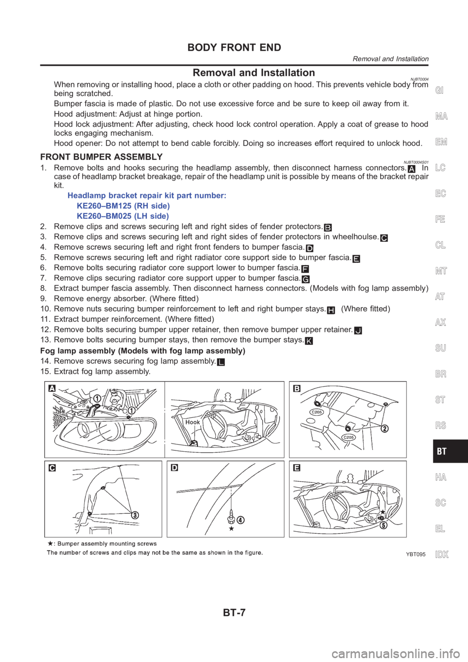
FRONT BUMPER ASSEMBLYNJBT0004S011. Remove bolts and hooks securing the headlamp assembly, then disconnectharness connectors.In
case of headlamp bracket breakage, repair of the headlamp unit is possibleby means of the bracket repair
kit.
Headlamp bracket repair kit part number:
KE260–BM125 (RH side)
KE260–BM025 (LH side)
2. Remove clips and screws securing left and right sides of fender protectors.
3. Remove clips and screws securing left and right sides of fender protectors in wheelhoulse.
4. Remove screws securing left and right front fenders to bumper fascia.
5. Remove screws securing left and right radiator core support side to bumper fascia.
6. Remove bolts securing radiator core support lower to bumper fascia.
7. Remove clips securing radiator core support upper to bumper fascia.
8. Extract bumper fascia assembly. Then disconnect harness connectors. (Models with fog lamp assembly)
9. Remove energy absorber. (Where fitted)
10. Remove nuts securing bumper reinforcement to left and right bumper stays.
(Where fitted)
11. Extract bumper reinforcement. (Where fitted)
12. Remove bolts securing bumper upper retainer, then remove bumper upperretainer.
13. Remove bolts securing bumper stays, then remove the bumper stays.
Fog lamp assembly (Models with fog lamp assembly)
14. Remove screws securing fog lamp assembly.
15. Extract fog lamp assembly.
YBT095
GI
MA
EM
LC
EC
FE
CL
MT
AT
AX
SU
BR
ST
RS
HA
SC
EL
IDX
BODY FRONT END
Removal and Installation
BT-7
Page 2704 of 3189
DescriptionNJEL0583The Smart Entrance Control Unit is applied for QG engine models and YD engine models with common rail.
OUTLINENJEL0583S01The smart entrance control unit totally controls the following body electrical system operations.
Warning chime, refer to EL-136, “WARNING CHIME”.
Rear defogger and door mirror defogger, refer to EL-173, “REAR WINDOW DEFOGGER”.
Power door lock, refer to EL-261, “POWER DOOR LOCK SYSTEM”.
Power door lock - Super lock - (RHD models), refer to EL-301, “POWER DOOR LOCK — SUPER LOCK
—”.
Multi-remote control system, refer to EL-352, “MULTI-REMOTE CONTROL SYSTEM”.
NATS (Nissan Anti-Theft system), refer to EL-386, “NATS (NISSAN ANTI-THEFT SYSTEM)”.
Interior lamp, refer to EL-80, “INTERIOR ROOM LAMP”.
Also, smart entrance control unit has the “sleep/wake-up control” function. Smart entrance control unit puts
itself (the whole smart entrance control unit) to sleep under certain conditions to prevent unnecessary power
consumption. Then, when a certain input is detected, the system wakes itself up. For more detailed
information, refer to EL-368, “SLEEP/WAKE-UP CONTROL”.
INTERIOR LAMP/SPOT LAMP/VANITY MIRROR ILLUMINATIONNJEL0583S02The lamps turn off automatically when the interior lamp, spot lamp or/and vanity mirror illumination are illumi-
nated with the ignition key in the OFF position, if the lamp remains lit by the door switch open signal or if the
lamp switch is in the ON position for more than 30 minutes.
After lamps are turned off by the smart entrance control unit, the lamps illuminate again when:
Driver’s door is locked or unlocked with remote controller, door lock/unlock switch or door key cylinder.
Ignition switch is turned to ON.
Door is opened or closed,
Key is inserted into ignition key cylinder.
REAR WINDOW DEFOGGER/DOOR MIRROR DEFOGGERNJEL0583S03Rear window defogger is turned off in approximately 15 minutes after the rear window defogger switch is turned
on.
SLEEP/WAKE-UP CONTROLNJEL0583S04Sleep ControlNJEL0583S0401“Sleep” control prevents unnecessary power consumption. After the following conditions are met, the smart
entrance control unit suspends the operation. The whole smart entrance control unit is set in the “sleep” mode.
Ignition switch “OFF”
All electrical loads (in the smart entrance control unit) “OFF”
Timer “OFF”
Each switch do not input
Wake-up ControlNJEL0583S0402When the smart entrance control unit detects a “wake-up” signal, it wakes up the whole system and starts
operating again. When any one of the following switches are turned ON, the “sleep” mode is canceled:
Ignition switch
Hazard switch
Headlamp switch
Hood switch
Trunk room lamp switch (sedan models)
Back door switch (hatchback or wagon models)
Each door switch
Trunk release switch (sedan models)
Back door release switch (hatchback or wagon models)
External trunk release switch (sedan models)
External back door release switch (hatchback or wagon models)
SMART ENTRANCE CONTROL SYSTEM
Description
EL-368
Page 2706 of 3189
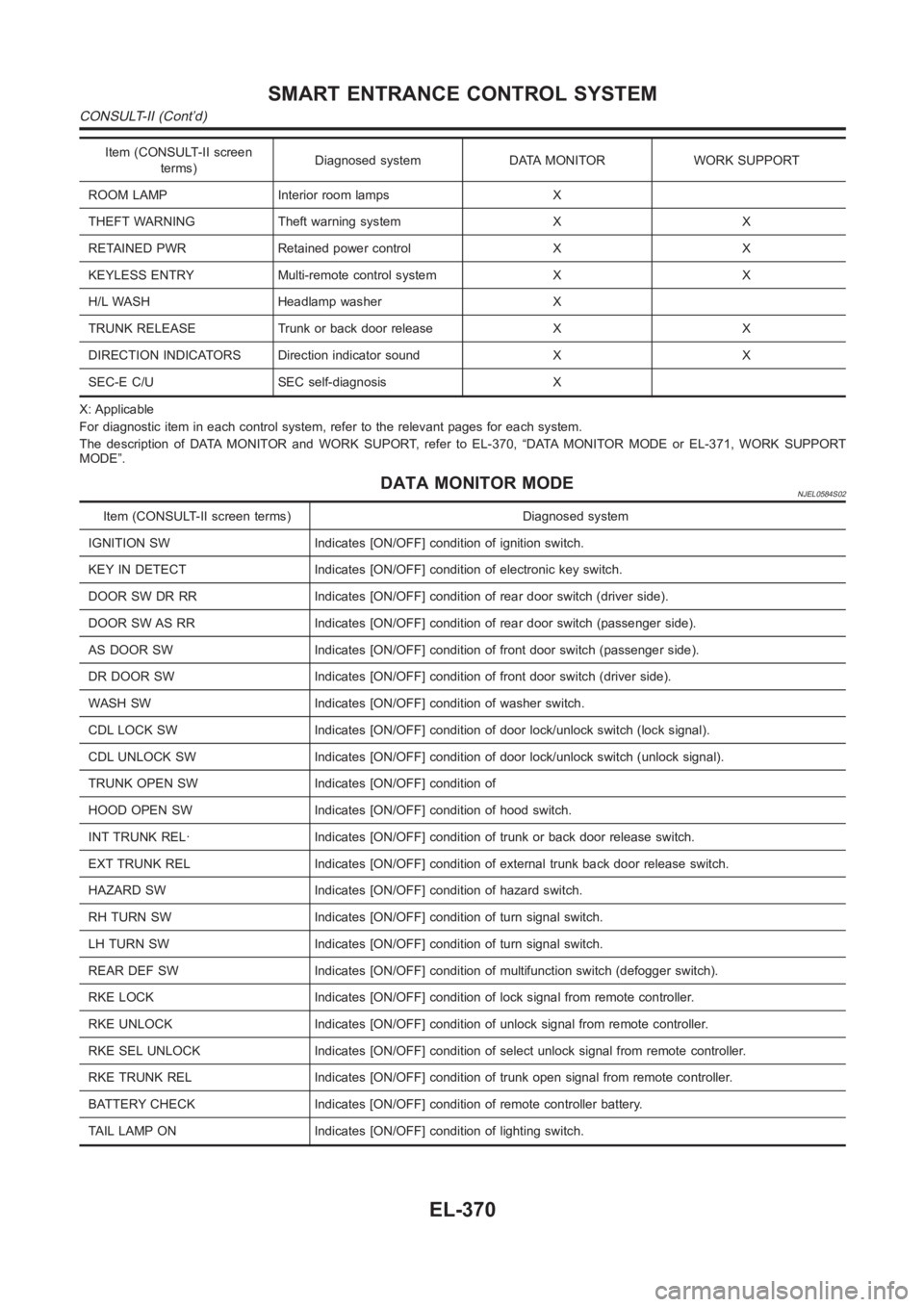
Item (CONSULT-II screen
terms)Diagnosed system DATA MONITOR WORK SUPPORT
ROOM LAMP Interior room lamps X
THEFT WARNING Theft warning system X X
RETAINED PWR Retained power control X X
KEYLESS ENTRY Multi-remote control system X X
H/L WASH Headlamp washer X
TRUNK RELEASE Trunk or back door release X X
DIRECTION INDICATORS Direction indicator sound X X
SEC-E C/U SEC self-diagnosis X
X: Applicable
For diagnostic item in each control system, refer to the relevant pages foreach system.
The description of DATA MONITOR and WORK SUPORT, refer to EL-370, “DATA MONITOR MODE or EL-371, WORK SUPPORT
MODE”.
DATA MONITOR MODENJEL0584S02
Item (CONSULT-II screen terms) Diagnosed system
IGNITION SW Indicates [ON/OFF] condition of ignition switch.
KEY IN DETECT Indicates [ON/OFF] condition of electronic key switch.
DOOR SW DR RR Indicates [ON/OFF] condition of rear door switch (driver side).
DOOR SW AS RR Indicates [ON/OFF] condition of rear door switch (passenger side).
AS DOOR SW Indicates [ON/OFF] condition of front door switch (passenger side).
DR DOOR SW Indicates [ON/OFF] condition of front door switch (driver side).
WASH SW Indicates [ON/OFF] condition of washer switch.
CDL LOCK SW Indicates [ON/OFF] condition of door lock/unlock switch (locksignal).
CDL UNLOCK SW Indicates [ON/OFF] condition of door lock/unlock switch (unlock signal).
TRUNK OPEN SW Indicates [ON/OFF] condition of
HOOD OPEN SW Indicates [ON/OFF] condition of hood switch.
INT TRUNK REL· Indicates [ON/OFF] condition of trunk or back door release switch.
EXT TRUNK REL Indicates [ON/OFF] condition of external trunk back door release switch.
HAZARD SW Indicates [ON/OFF] condition of hazard switch.
RH TURN SW Indicates [ON/OFF] condition of turn signal switch.
LH TURN SW Indicates [ON/OFF] condition of turn signal switch.
REAR DEF SW Indicates [ON/OFF] condition of multifunction switch (defogger switch).
RKE LOCK Indicates [ON/OFF] condition of lock signal from remote controller.
RKE UNLOCK Indicates [ON/OFF] condition of unlock signal from remote controller.
RKE SEL UNLOCK Indicates [ON/OFF] condition of select unlock signal from remote controller.
RKE TRUNK REL Indicates [ON/OFF] condition of trunk open signal from remote controller.
BATTERY CHECK Indicates [ON/OFF] condition of remote controller battery.
TAIL LAMP ON Indicates [ON/OFF] condition of lighting switch.
SMART ENTRANCE CONTROL SYSTEM
CONSULT-II (Cont’d)
EL-370
Page 2712 of 3189
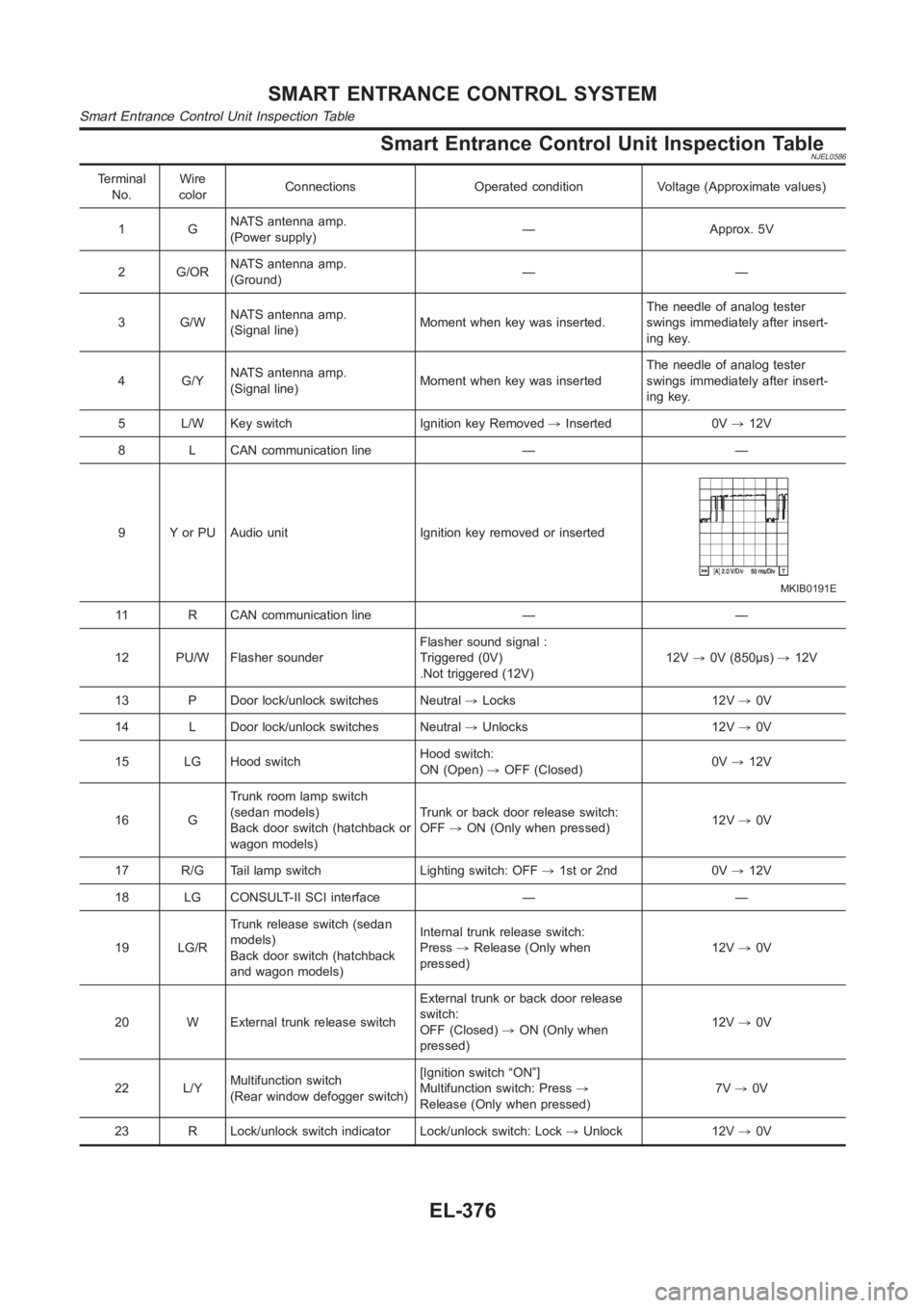
Smart Entrance Control Unit Inspection TableNJEL0586
Terminal
No.Wire
colorConnections Operated condition Voltage (Approximate values)
1GNATS antenna amp.
(Power supply)— Approx. 5V
2 G/ORNATS antenna amp.
(Ground)——
3 G/WNATS antenna amp.
(Signal line)Moment when key was inserted.The needle of analog tester
swings immediately after insert-
ing key.
4 G/YNATS antenna amp.
(Signal line)Moment when key was insertedThe needle of analog tester
swings immediately after insert-
ing key.
5 L/W Key switch Ignition key Removed,Inserted 0V,12V
8 L CAN communication line — —
9 Y or PU Audio unit Ignition key removed or inserted
MKIB0191E
11 R CAN communication line — —
12 PU/W Flasher sounderFlasher sound signal :
Triggered (0V)
.Not triggered (12V)12V,0V (850μs),12V
13 P Door lock/unlock switches Neutral,Locks 12V,0V
14 L Door lock/unlock switches Neutral,Unlocks 12V,0V
15 LG Hood switchHood switch:
ON (Open),OFF (Closed)0V,12V
16 GTrunk room lamp switch
(sedan models)
Back door switch (hatchback or
wagon models)Trunk or back door release switch:
OFF,ON (Only when pressed)12V,0V
17 R/G Tail lamp switch Lighting switch: OFF,1st or 2nd 0V,12V
18 LG CONSULT-II SCI interface — —
19 LG/RTrunk release switch (sedan
models)
Back door switch (hatchback
and wagon models)Internal trunk release switch:
Press,Release (Only when
pressed)12V,0V
20 W External trunk release switchExternal trunk or back door release
switch:
OFF (Closed),ON (Only when
pressed)12V,0V
22 L/YMultifunction switch
(Rear window defogger switch)[Ignition switch “ON”]
Multifunction switch: Press,
Release (Only when pressed)7V,0V
23 R Lock/unlock switch indicator Lock/unlock switch: Lock,Unlock 12V,0V
SMART ENTRANCE CONTROL SYSTEM
Smart Entrance Control Unit Inspection Table
EL-376
Page 3005 of 3189
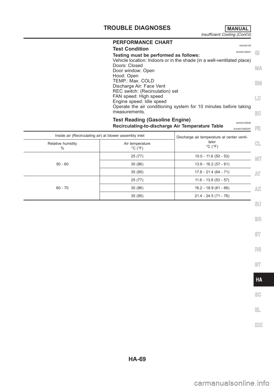
PERFORMANCE CHART=NJHA0150Test ConditionNJHA0150S01Testing must be performed as follows:
Vehicle location: Indoors or in the shade (in a well-ventilated place)
Doors: Closed
Door window: Open
Hood: Open
TEMP.: Max. COLD
Discharge Air: Face Vent
REC switch: (Recirculation) set
FAN speed: High speed
Engine speed: Idle speed
Operate the air conditioning system for 10 minutes before taking
measurements.
Test Reading (Gasoline Engine)NJHA0150S02Recirculating-to-discharge Air Temperature TableNJHA0150S0201
Inside air (Recirculating air) at blower assembly inlet
Discharge air temperature at center venti-
lator
°C (°F) Relative humidity
%Air temperature
°C (°F)
50 - 6025 (77) 10.0 - 11.6 (50 - 53)
30 (86) 13.9 - 16.2 (57 - 61)
35 (95) 17.8 - 21.4 (64 - 71)
60 - 7025 (77) 11.6 - 13.9 (53 - 57)
30 (86) 16.2 - 18.9 (61 - 66)
35 (95) 21.4 - 24.5 (71 - 76)
GI
MA
EM
LC
EC
FE
CL
MT
AT
AX
SU
BR
ST
RS
BT
SC
EL
IDX
TROUBLE DIAGNOSESMANUAL
Insufficient Cooling (Cont’d)
HA-69