2003 NISSAN ALMERA N16 SC-13
[x] Cancel search: SC-13Page 1739 of 3189
![NISSAN ALMERA N16 2003 Electronic Repair Manual TROUBLE DIAGNOSIS — GENERAL DESCRIPTION
AT-283
[EXC.F/EURO-OBD]
D
E
F
G
H
I
J
K
L
MA
B
AT
TROUBLE DIAGNOSIS — GENERAL DESCRIPTIONPFP:00000
Symptom ChartECS007QV
Numbers are arranged in order of in](/manual-img/5/57350/w960_57350-1738.png "NISSAN ALMERA N16 2003 Electronic Repair Manual TROUBLE DIAGNOSIS — GENERAL DESCRIPTION
AT-283
[EXC.F/EURO-OBD]
D
E
F
G
H
I
J
K
L
MA
B
AT
TROUBLE DIAGNOSIS — GENERAL DESCRIPTIONPFP:00000
Symptom ChartECS007QV
Numbers are arranged in order of in")
TROUBLE DIAGNOSIS — GENERAL DESCRIPTION
AT-283
[EXC.F/EURO-OBD]
D
E
F
G
H
I
J
K
L
MA
B
AT
TROUBLE DIAGNOSIS — GENERAL DESCRIPTIONPFP:00000
Symptom ChartECS007QV
Numbers are arranged in order of inspection.
Perform inspections starting with number one and work up.
Symptom Condition Diagnostic Item Reference Page
Engine cannot start in “P” and “N”
positions.
AT-309, "
2. Engine Cannot Be Started
In “P” and “N” Position"
ON vehicle1. Ignition switch and starterEL-11, "POWER SUP-
PLY ROUTING",
SC-13, "STARTING SYS-
TEM"
2. Control cable adjustmentAT- 4 0 8 , "Control Cable
Adjustment"
3. PNP switch adjustmentAT- 4 0 8 , "
Park/Neutral
Position (PNP) Switch
Adjustment"
Engine starts in position other than
“N” and “P” positions.
AT-309, "
2. Engine Cannot Be Started
In “P” and “N” Position"
ON vehicle1. Control cable adjustmentAT- 4 0 8 , "
Control Cable
Adjustment"
2. PNP switch adjustmentAT- 4 0 8 , "
Park/Neutral
Position (PNP) Switch
Adjustment"
Transaxle noise in “P” and “N” posi-
tions.ON vehicle1. Fluid levelAT- 2 6 1 , "
FLUID LEVEL
CHECK"
2. Line pressure testAT- 2 6 5 , "Line Pressure
Te s t"
3. Throttle position sensor (Accelerator
pedal position (APP) sensor)AT- 3 5 2 , "ACCELE
RATOR PEDAL POSI-
TION (APP) SENSOR"
4. Vehicle speed sensor·A/T (Revolution
sensor) and vehicle speed sensor·MTRAT- 3 4 3 , "
VEHICLE
SPEED SENSOR - A/T
(REVOLUTION SEN-
SOR)"
AT- 3 4 8 , "DTC VEHICLE
SPEED SENSOR MTR"
5. Engine speed signalAT- 3 8 3 , "ENGINE SPEED
SIGNAL"
OFF vehicle6. Oil pumpAT- 4 3 5 , "
Oil Pump"
7. Torque converterAT- 4 1 7 , "
Locations of
Adjusting Shims, Needle
Bearings, Thrust Washers
and Snap Rings"
Vehicle moves when changing into “P”
position, or parking gear does not dis-
engage when shifted out of “P” posi-
tion.
AT-310, "
3. In “P” Position, Vehicle
Moves Forward Or Backward When
Pushed"
ON vehicle 1. Control cable adjustmentAT- 4 0 8 , "Control Cable
Adjustment"
OFF vehicle 2. Parking componentsAT- 4 7 8 , "
Output Shaft,
Idler Gear, Reduction Pin-
ion Gear and Bearing
Retainer"
Vehicle runs in “N” position.
AT- 3 11 , "
4. In “N” Position, Vehicle
Moves"
ON vehicle 1. Control cable adjustmentAT- 4 0 8 , "Control Cable
Adjustment"
OFF vehicle2. Forward clutchAT- 4 6 4 , "
Forward and
Overrun Clutches"
3. Reverse clutchAT- 4 5 5 , "Reverse Clutch"
4. Overrun clutchAT- 4 6 4 , "Forward and
Overrun Clutches"
Page 1766 of 3189
![NISSAN ALMERA N16 2003 Electronic Repair Manual AT-310
[EXC.F/EURO-OBD]
TROUBLE DIAGNOSES FOR SYMPTOMS
1. CHECK PNP SWITCH CIRCUIT
With CONSULT-II
Does “TCM INPUT SIGNALS” in “DATA MONITOR” show damage to PNP switch circuit?
Without CONSULT](/manual-img/5/57350/w960_57350-1765.png "NISSAN ALMERA N16 2003 Electronic Repair Manual AT-310
[EXC.F/EURO-OBD]
TROUBLE DIAGNOSES FOR SYMPTOMS
1. CHECK PNP SWITCH CIRCUIT
With CONSULT-II
Does “TCM INPUT SIGNALS” in “DATA MONITOR” show damage to PNP switch circuit?
Without CONSULT")
AT-310
[EXC.F/EURO-OBD]
TROUBLE DIAGNOSES FOR SYMPTOMS
1. CHECK PNP SWITCH CIRCUIT
With CONSULT-II
Does “TCM INPUT SIGNALS” in “DATA MONITOR” show damage to PNP switch circuit?
Without CONSULT-II
Does self-diagnosis show damage to PNP switch circuit?
Ye s o r N o
Yes >> Check PNP switch circuit. Refer to AT- 3 3 3 , "21. TCM
Self-diagnosis Does Not Activate (PNP & Overdrive
Control Switches, and Throttle Position Sensor Circuit
Checks)" .
No >> GO TO 2
2. CHECK PNP SWITCH INSPECTION
Check for short or open of PNP switch harness connector terminals 1 and 2.
Refer to AT- 3 3 3 , "
21. TCM Self-diagnosis Does Not Activate (PNP &
Overdrive Control Switches, and Throttle Position Sensor Circuit
Checks)" .
OK or NG
OK >> GO TO 3
NG >> Repair or replace PNP switch.
3. CHECK STARTING SYSTEM
Check starting system. Refer to SC-13, "STARTING SYSTEM".
OK or NG
OK >>INSPECTION END
NG >> Repair or replace damaged parts.
3. In “P” Position, Vehicle Moves Forward Or Backward When PushedECS007R2
SYMPTOM:
Vehicle moves when it is pushed forward or backward with selector lever in “P” position.
1. CHECK PARKING COMPONENTS
Check parking components. Refer to AT- 4 1 3 , "
Output Shaft, Idler
Gear, Reduction Pinion Gear and Bearing Retainer" .
OK or NG
OK >>INSPECTION END
NG >> Repair or replace damaged parts.
SCIA0706E
SAT408JA
SAT282F
Page 2745 of 3189
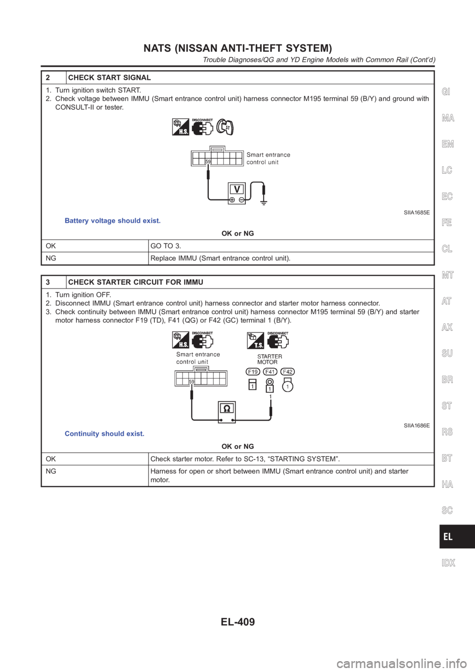
2 CHECK START SIGNAL
1. Turn ignition switch START.
2. Check voltage between IMMU (Smart entrance control unit) harness connector M195 terminal 59 (B/Y) and ground with
CONSULT-II or tester.
SIIA1685E
Battery voltage should exist.
OK or NG
OK GO TO 3.
NG Replace IMMU (Smart entrance control unit).
3 CHECK STARTER CIRCUIT FOR IMMU
1. Turn ignition OFF.
2. Disconnect IMMU (Smart entrance control unit) harness connector and starter motor harness connector.
3. Check continuity between IMMU (Smart entrance control unit) harness connector M195 terminal 59 (B/Y) and starter
motor harness connector F19 (TD), F41 (QG) or F42 (GC) terminal 1 (B/Y).
SIIA1686E
Continuity should exist.
OK or NG
OK Check starter motor. Refer to SC-13, “STARTING SYSTEM”.
NG Harness for open or short between IMMU (Smart entrance control unit) andstarter
motor.
GI
MA
EM
LC
EC
FE
CL
MT
AT
AX
SU
BR
ST
RS
BT
HA
SC
IDX
NATS (NISSAN ANTI-THEFT SYSTEM)
Trouble Diagnoses/QG and YD Engine Models with Common Rail (Cont’d)
EL-409
Page 2747 of 3189
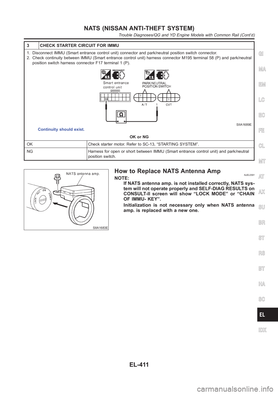
3 CHECK STARTER CIRCUIT FOR IMMU
1. Disconnect IMMU (Smart entrance control unit) connector and park/neutral position switch connector.
2. Check continuity between IMMU (Smart entrance control unit) harness connector M195 terminal 58 (P) and park/neutral
position switch harness connector F17 terminal 1 (P).
SIIA1689E
Continuity should exist.
OK or NG
OK Check starter motor. Refer to SC-13, “STARTING SYSTEM”.
NG Harness for open or short between IMMU (Smart entrance control unit) andpark/neutral
position switch.
SIIA1683E
How to Replace NATS Antenna AmpNJEL0591NOTE:
If NATS antenna amp. is not installed correctly, NATS sys-
tem will not operate properly and SELF-DIAG RESULTS on
CONSULT-II screen will show “LOCK MODE” or “CHAIN
OF IMMU- KEY”.
Initialization is not necessary only when NATS antenna
amp. is replaced with a new one.
GI
MA
EM
LC
EC
FE
CL
MT
AT
AX
SU
BR
ST
RS
BT
HA
SC
IDX
NATS (NISSAN ANTI-THEFT SYSTEM)
Trouble Diagnoses/QG and YD Engine Models with Common Rail (Cont’d)
EL-411
Page 3119 of 3189
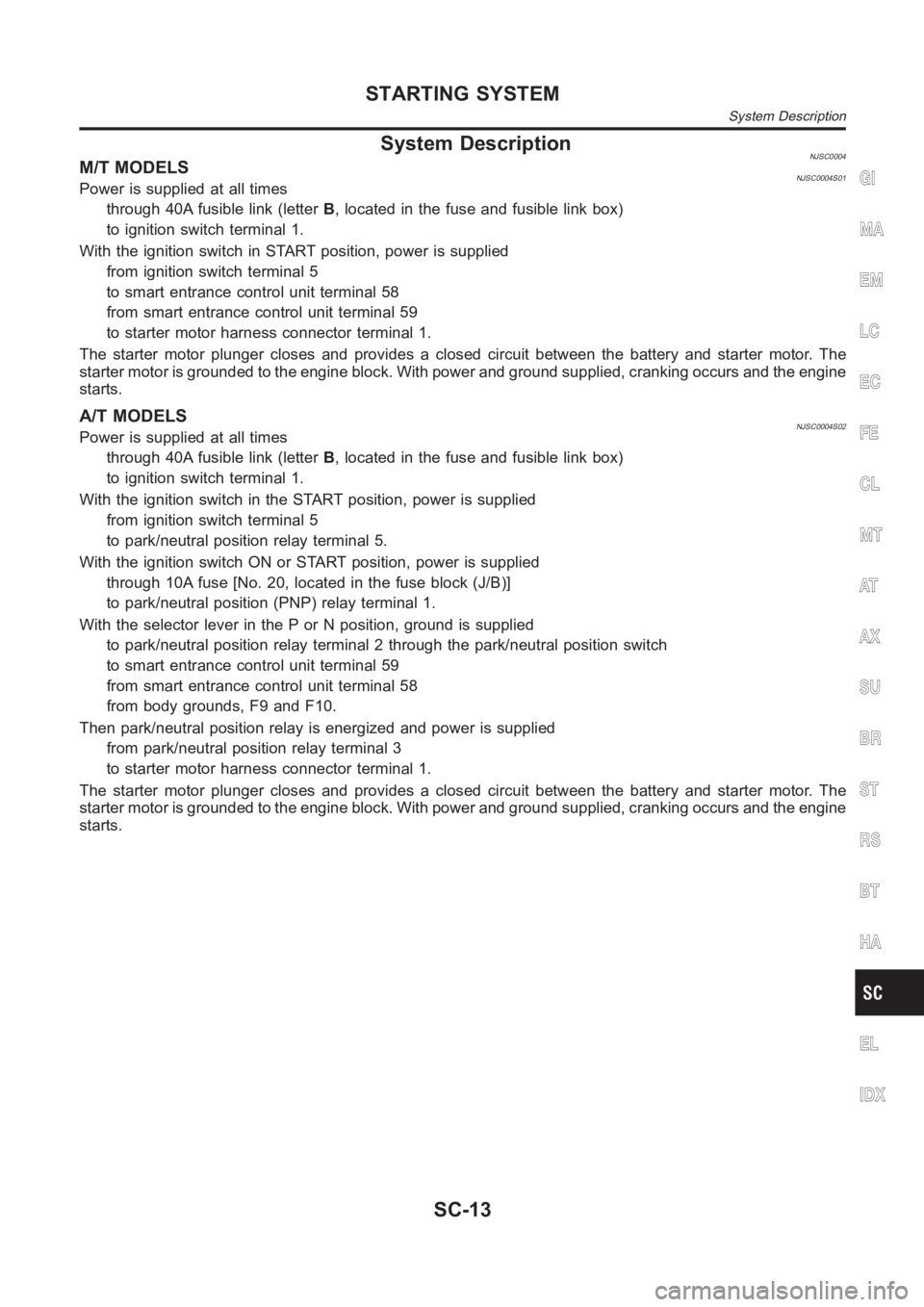
System DescriptionNJSC0004M/T MODELSNJSC0004S01Power is supplied at all times
through 40A fusible link (letterB, located in the fuse and fusible link box)
to ignition switch terminal 1.
With the ignition switch in START position, power is supplied
from ignition switch terminal 5
to smart entrance control unit terminal 58
from smart entrance control unit terminal 59
to starter motor harness connector terminal 1.
The starter motor plunger closes and provides a closed circuit between thebattery and starter motor. The
starter motor is grounded to the engine block. With power and ground supplied, cranking occurs and the engine
starts.
A/T MODELSNJSC0004S02Power is supplied at all times
through 40A fusible link (letterB, located in the fuse and fusible link box)
to ignition switch terminal 1.
With the ignition switch in the START position, power is supplied
from ignition switch terminal 5
to park/neutral position relay terminal 5.
With the ignition switch ON or START position, power is supplied
through 10A fuse [No. 20, located in the fuse block (J/B)]
to park/neutral position (PNP) relay terminal 1.
With the selector lever in the P or N position, ground is supplied
to park/neutral position relay terminal 2 through the park/neutral position switch
to smart entrance control unit terminal 59
from smart entrance control unit terminal 58
from body grounds, F9 and F10.
Then park/neutral position relay is energized and power is supplied
from park/neutral position relay terminal 3
to starter motor harness connector terminal 1.
The starter motor plunger closes and provides a closed circuit between thebattery and starter motor. The
starter motor is grounded to the engine block. With power and ground supplied, cranking occurs and the engine
starts.
GI
MA
EM
LC
EC
FE
CL
MT
AT
AX
SU
BR
ST
RS
BT
HA
EL
IDX
STARTING SYSTEM
System Description
SC-13
Page 3183 of 3189
Starting system...............................................SC-13
Steering linkage ..............................................ST-15
Steering switch................................................EL-41
Steering wheel and column ............................ST-10
Steering wheel play ..........................................ST-6
Steering wheel turning force .............................ST-8
Stop lamp switch (QG engine) ......EC-361, EC-630
Stop lamp <0011001100110011001100110011001100110011001100110011001100110011001100110011001100110011001100110011001100110011001100110011001100110011001100110011001100110011001100110011001100110011001100110011001100
110011001100110011[.EL-58
STOP/L - Wiring diagram................................EL-58
Striking rod (M/T) ...............................MT-32, 56, 94
Strut (front) <0011001100110011001100110011001100110011001100110011001100110011001100110011001100110011001100110011001100110011001100110011001100110011001100110011001100110011001100110011001100110011001100110011001100
11[....SU-9
Strut (rear) <0011001100110011001100110011001100110011001100110011001100110011001100110011001100110011001100110011001100110011001100110011001100110011001100110011001100110011001100110011001100110011001100110011001100
110011[..SU-20
Sub-gear (M/T) .........................................MT-31, 55
Sun roof, electric ...........................................EL-249
Sunload sensor...........ATC-106, ATC-108, ATC-118
Sunroof<0011001100110011001100110011001100110011001100110011001100110011001100110011001100110011001100110011001100110011001100110011001100110011001100110011001100110011001100110011001100110011001100110011001100
1100110011001100110011[....BT-60
Super lock <0011001100110011001100110011001100110011001100110011001100110011001100110011001100110011001100110011001100110011001100110011001100110011001100110011001100110011001100110011001100110011001100110011001100
11001100110028[L-301
Supplemental restraint system - Wiring
diagram <0011001100110011001100110011001100110011001100110011001100110011001100110011001100110011001100110011001100110011001100110011001100110011001100110011001100110011001100110011001100110011001100110011001100
1100110011001100110035[S-46
Supplemental Restraint System .....................RS-20
Symbols and abbreviations..............................GI-11
Symptom matrix chart
(QG engine)..................................EC-70, EC-449
Symptom matrix chart (YD engine)................EC-53
Synchronizer (M/T) ............................MT-31, 55, 93
System readiness test (SRT) code
(QG engine) ................................................EC-40
T
Tachometer <0011001100110011001100110011001100110011001100110011001100110011001100110011001100110011001100110011001100110011001100110011001100110011001100110011001100110011001100110011001100110011001100110011001100
1100110028[L-110
Tail lamp <0011001100110011001100110011001100110011001100110011001100110011001100110011001100110011001100110011001100110011001100110011001100110011001100110011001100110011001100110011001100110011001100110011001100
110011001100110011[...EL-55
TCM circuit diagram ........................................AT-15
TCM inspection table .......................AT-107, AT-303
Thermostat................................................LC-15,40
Three way catalyst function
(QG engine) ..............................................EC-247
Three way catalyst precautions.........................GI-6
Throttle body (QG engine) .............................EM-18
Throttle control motor relay
(QG engine)................................EC-286, EC-587
Throttle position sensor (TPS)
(QG engine) ..EC-200, EC-206, EC-336, EC-342,
EC-344, EC-526, EC-532, EC-609,
EC-615, EC-617
Throttle position switch ....................AT-244, AT-340
Throttle valve closed position learning
(QG engine)..................................EC-31, EC-426
Throwout bearing - See Clutch release
bearing ..................................................CL-17,20
Tie-rod ball joints.............................................ST- 1 9
Tie-rod <0011001100110011001100110011001100110011001100110011001100110011001100110011001100110011001100110011001100110011001100110011001100110011001100110011001100110011001100110011001100110011001100110011001100
1100110011001100110011[.....ST-15
Tightening torque of standard bolts.................GI-50
Timing chain (QG engine)..............................EM-47
Timing chain (YD engine) ..............................EM-20
Tire size <0011001100110011001100110011001100110011001100110011001100110011001100110011001100110011001100110011001100110011001100110011001100110011001100110011001100110011001100110011001100110011001100110011001100
110011001100110011[....GI-44
Torque converter installation ............AT-412, AT-509
Tow truck towing ..............................................GI-48
TPS1 - Wiring diagram
(QG engine)................................EC-208, EC-534TPS2 - Wiring diagram
(QG engine) ................................EC-338, EC-611
TPS3 - Wiring diagram
(QG engine)................................EC-202, EC-528
Transmission case (M/T) ...................MT-30, 54, 92
Tread-FR&RR (Dimensions)............................GI-44
Trim <0011001100110011001100110011001100110011001100110011001100110011001100110011001100110011001100110011001100110011001100110011001100110011001100110011001100110011001100110011001100110011001100110011001100
1100110011001100110011001100110011[......BT-31
Trouble diagnoses ...........................................GI-32
Trunk lid finisher..............................................BT- 4 5
Trunk lid opener - See Trunk lid .....................BT-10
Trunk lid trim <0011001100110011001100110011001100110011001100110011001100110011001100110011001100110011001100110011001100110011001100110011001100110011001100110011001100110011001100110011001100110011001100110011001100
11[BT-45
Trunk lid <0011001100110011001100110011001100110011001100110011001100110011001100110011001100110011001100110011001100110011001100110011001100110011001100110011001100110011001100110011001100110011001100110011001100
110011001100110011[...BT-10
Trunk room lamp ...........................................EL-108
Trunk room trim...............................................BT-45
TURN - Wiring diagram ..................................EL-71
Turn signal lamp .............................................EL-67
Two trip detection logic
(QG engine)..................................EC-36, EC-430
Two-pole lift <0011001100110011001100110011001100110011001100110011001100110011001100110011001100110011001100110011001100110011001100110011001100110011001100110011001100110011001100110011001100110011001100110011001100
11[..GI-47
U
Under body <0011001100110011001100110011001100110011001100110011001100110011001100110011001100110011001100110011001100110011001100110011001100110011001100110011001100110011001100110011001100110011001100110011001100
11001100110025[T- 7 7
V
Vacuum hose (brake system).........................BR-22
Vacuum hose drawing (Engine control)
(QG engine)..................................EC-22, EC-417
Vacuum pump.................................................BR-23
Valve clearance (YD engine) .........................EM-59
Valve guide (QG engine) ...............................EM-63
Valve guide (YD engine) ................................EM-50
Valve lifter<0011001100110011001100110011001100110011001100110011001100110011001100110011001100110011001100110011001100110011001100110011001100110011001100110011001100110011001100110011001100110011001100110011001100
110011[...EM-41
Valve seat (QG engine) .................................EM-64
Valve seat (YD engine) ..................................EM-52
Valve spring (QG engine) ..............................EM-66
Valve spring (YD engine) ...............................EM-54
Vehicle speed sensor (VSS)
(QG engine)................................EC-258, EC-679
Vehicle speed sensor (VSS)
(YD engine)...............................................EC-105
Ventilation air filter (manual A/C) ...................HA-95
Ventilation air filter ......................................ATC-129
Viscosity number (SAE) .................................MA-20
Viscous coupling (FF M/T) .............................MT-93
VSS - Wiring diagram (YD engine) ..............EC-105
W
WARN - Wiring diagram ...............................EL-130
Warning chime ..............................................EL-136
Warning lamps ..............................................EL-129
Washer, front .................................................EL-158
Water pump ..............................................LC-14, 38
Water temperature gauge .............................EL-110
Weatherstrip - See Exterior ............................BT-47
GI
MA
EM
LC
EC
FE
CL
MT
AT
AX
SU
BR
ST
RS
BT
HA
SC
EL
ALPHABETICAL INDEX
IDX-9