Page 2875 of 3189
CAN COMMUNICATION CIRCUIT CHECK=NJEL0545S08
1 CHECK CONNECTOR
1. Turn ignition switch OFF.
2. Disconnect the negative battery cable.
3. Check following terminals and connector for damage, bend and loose connection (meter-side, control unit-side, control
module-side and harness-side).
Combination meter
Smart entrance control unit
ECM
Between ECM and smart entrance control unit
OK or NG
OK GO TO 2.
NG Repair terminal or connector.
2 CHECK HARNESS FOR SHORT CIRCUIT
1. Disconnect combination meter connector, smart entrance control unit connector and harness connector M202 (LHD
models) or harness connector M159 (RHD models).
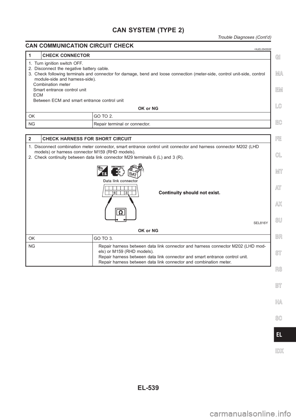
2. Check continuity between data link connector M29 terminals 6 (L) and 3 (R).
SEL816Y
OK or NG
OK GO TO 3.
NG Repair harness between data link connector and harness connector M202 (LHD mod-
els) or M159 (RHD models).
Repair harness between data link connector and smart entrance control unit.
Repair harness between data link connector and combination meter.
GI
MA
EM
LC
EC
FE
CL
MT
AT
AX
SU
BR
ST
RS
BT
HA
SC
IDX
CAN SYSTEM (TYPE 2)
Trouble Diagnoses (Cont’d)
EL-539
Page 2876 of 3189
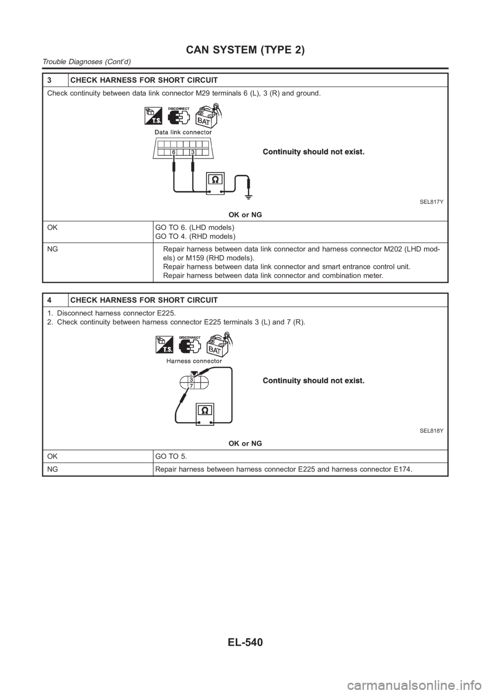
3 CHECK HARNESS FOR SHORT CIRCUIT
Check continuity between data link connector M29 terminals 6 (L), 3 (R) andground.
SEL817Y
OK or NG
OK GO TO 6. (LHD models)
GO TO 4. (RHD models)
NG Repair harness between data link connector and harness connector M202 (LHD mod-
els) or M159 (RHD models).
Repair harness between data link connector and smart entrance control unit.
Repair harness between data link connector and combination meter.
4 CHECK HARNESS FOR SHORT CIRCUIT
1. Disconnect harness connector E225.
2. Check continuity between harness connector E225 terminals 3 (L) and 7 (R).
SEL818Y
OK or NG
OK GO TO 5.
NG Repair harness between harness connector E225 and harness connector E174.
CAN SYSTEM (TYPE 2)
Trouble Diagnoses (Cont’d)
EL-540
Page 2878 of 3189
7 CHECK HARNESS FOR SHORT CIRCUIT
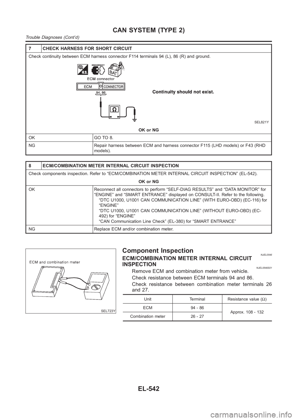
Check continuity between ECM harness connector F114 terminals 94 (L), 86 (R) and ground.
SEL821Y
OK or NG
OK GO TO 8.
NG Repair harness between ECM and harness connector F115 (LHD models) or F43 (RHD
models).
8 ECM/COMBINATION METER INTERNAL CIRCUIT INSPECTION
Check components inspection. Refer to “ECM/COMBINATION METER INTERNAL CIRCUIT INSPECTION” (EL-542).
OK or NG
OK Reconnect all connectors to perform “SELF-DIAG RESULTS” and “DATA MONITOR” for
“ENGINE” and “SMART ENTRANCE” displayed on CONSULT-II. Refer to the following.
“DTC U1000, U1001 CAN COMMUNICATION LINE” (WITH EURO-OBD) (EC-116) for
“ENGINE”
“DTC U1000, U1001 CAN COMMUNICATION LINE” (WITHOUT EURO-OBD) (EC-
492) for “ENGINE”
“CAN Communication Line Check” (EL-380) for “SMART ENTRANCE”
NG Replace ECM and/or combination meter.
SEL723Y
Component InspectionNJEL0546ECM/COMBINATION METER INTERNAL CIRCUIT
INSPECTION
NJEL0546S01Remove ECM and combination meter from vehicle.
Check resistance between ECM terminals 94 and 86.
Check resistance between combination meter terminals 26
and 27.
Unit Terminal Resistance value (Ω)
ECM 94 - 86
Approx. 108 - 132
Combination meter 26 - 27
CAN SYSTEM (TYPE 2)
Trouble Diagnoses (Cont’d)
EL-542
Page 2934 of 3189
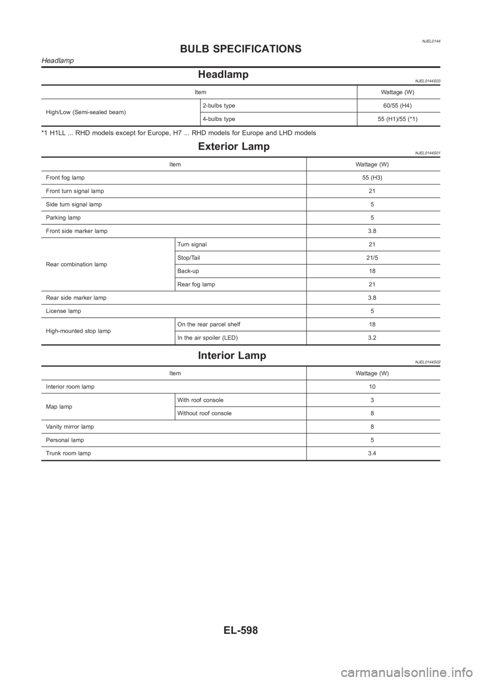
NJEL0144
HeadlampNJEL0144S03
Item Wattage (W)
High/Low (Semi-sealed beam)2-bulbs type 60/55 (H4)
4-bulbs type 55 (H1)/55 (*1)
*1 H1LL ... RHD models except for Europe, H7 ... RHD models for Europe and LHDmodels
Exterior LampNJEL0144S01
Item Wattage (W)
Front fog lamp55 (H3)
Front turn signal lamp21
Side turn signal lamp5
Parking lamp5
Front side marker lamp3.8
Rear combination lampTurn signal 21
Stop/Tail 21/5
Back-up 18
Rear fog lamp 21
Rear side marker lamp3.8
License lamp5
High-mounted stop lampOn the rear parcel shelf 18
In the air spoiler (LED) 3.2
Interior LampNJEL0144S02
Item Wattage (W)
Interior room lamp10
Map lampWith roof console 3
Without roof console 8
Vanity mirror lamp8
Personal lamp5
Trunk room lamp3.4
BULB SPECIFICATIONS
Headlamp
EL-598
Page 2992 of 3189
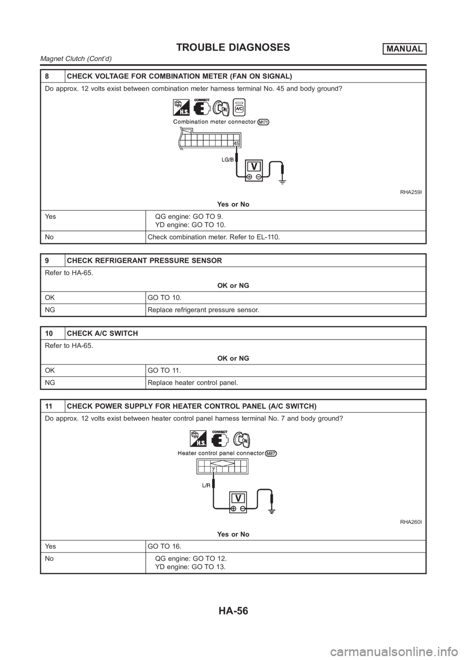
8 CHECK VOLTAGE FOR COMBINATION METER (FAN ON SIGNAL)
Do approx. 12 volts exist between combination meter harness terminal No. 45 and body ground?
RHA259I
YesorNo
Yes QG engine: GO TO 9.
YD engine: GO TO 10.
No Check combination meter. Refer to EL-110.
9 CHECK REFRIGERANT PRESSURE SENSOR
Refer to HA-65.
OK or NG
OK GO TO 10.
NG Replace refrigerant pressure sensor.
10 CHECK A/C SWITCH
Refer to HA-65.
OK or NG
OK GO TO 11.
NG Replace heater control panel.
11 CHECK POWER SUPPLY FOR HEATER CONTROL PANEL (A/C SWITCH)
Do approx. 12 volts exist between heater control panel harness terminal No. 7 and body ground?
RHA260I
YesorNo
Yes GO TO 16.
No QG engine: GO TO 12.
YD engine: GO TO 13.
TROUBLE DIAGNOSESMANUAL
Magnet Clutch (Cont’d)
HA-56
Page 2993 of 3189
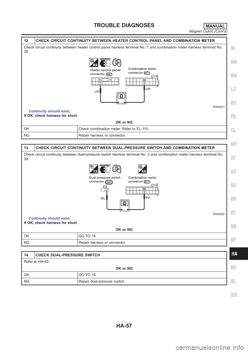
12 CHECK CIRCUIT CONTINUITY BETWEEN HEATER CONTROL PANEL AND COMBINATIONMETER
Check circuit continuity between heater control panel harness terminal No. 7 and combination meter harness terminal No.
39.
RHA261I
Continuity should exist.
If OK, check harness for short.
OK or NG
OK Check combination meter. Refer to EL-110.
NG Repair harness or connector.
13 CHECK CIRCUIT CONTINUITY BETWEEN DUAL-PRESSURE SWITCH AND COMBINATION METER
Check circuit continuity between dual-pressure switch harness terminalNo. 2 and combination meter harness terminal No.
39.
RHA262I
Continuity should exist.
If OK, check harness for short.
OK or NG
OK GO TO 14.
NG Repair harness or connector.
14 CHECK DUAL-PRESSURE SWITCH
Refer to HA-65.
OK or NG
OK GO TO 15.
NG Repair dual-pressure switch.
GI
MA
EM
LC
EC
FE
CL
MT
AT
AX
SU
BR
ST
RS
BT
SC
EL
IDX
TROUBLE DIAGNOSESMANUAL
Magnet Clutch (Cont’d)
HA-57
Page 2994 of 3189
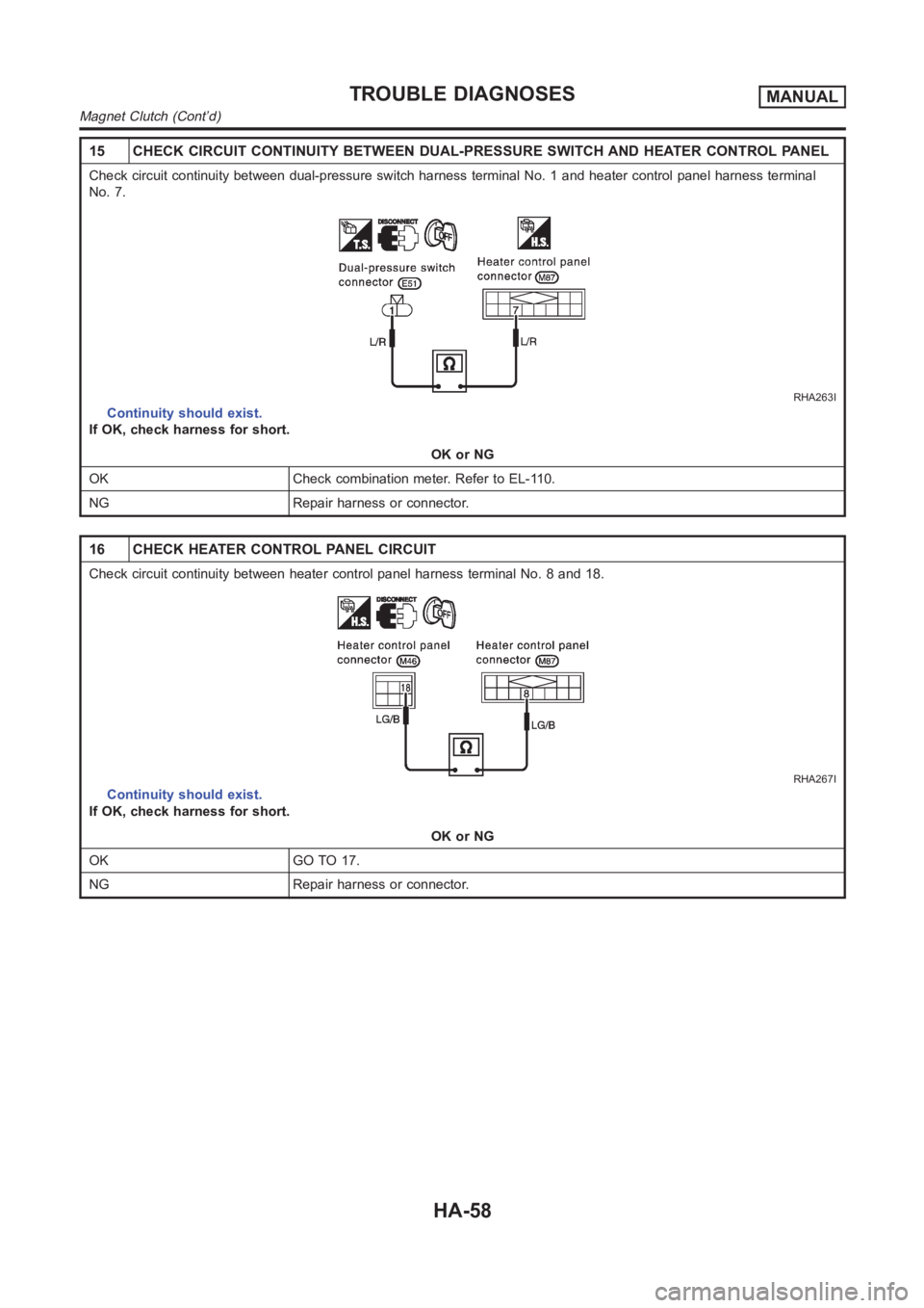
15 CHECK CIRCUIT CONTINUITY BETWEEN DUAL-PRESSURE SWITCH AND HEATER CONTROL PANEL
Check circuit continuity between dual-pressure switch harness terminalNo. 1 and heater control panel harness terminal
No. 7.
RHA263I
Continuity should exist.
If OK, check harness for short.
OK or NG
OK Check combination meter. Refer to EL-110.
NG Repair harness or connector.
16 CHECK HEATER CONTROL PANEL CIRCUIT
Check circuit continuity between heater control panel harness terminal No. 8 and 18.
RHA267I
Continuity should exist.
If OK, check harness for short.
OK or NG
OK GO TO 17.
NG Repair harness or connector.
TROUBLE DIAGNOSESMANUAL
Magnet Clutch (Cont’d)
HA-58
Page 2995 of 3189
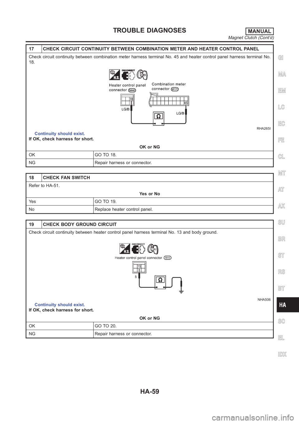
17 CHECK CIRCUIT CONTINUITY BETWEEN COMBINATION METER AND HEATER CONTROLPANEL
Check circuit continuity between combination meter harness terminal No.45 and heater control panel harness terminal No.
18.
RHA265I
Continuity should exist.
If OK, check harness for short.
OK or NG
OK GO TO 18.
NG Repair harness or connector.
18 CHECK FAN SWITCH
Refer to HA-51.
YesorNo
Yes GO TO 19.
No Replace heater control panel.
19 CHECK BODY GROUND CIRCUIT
Check circuit continuity between heater control panel harness terminal No. 13 and body ground.
NHA506
Continuity should exist.
If OK, check harness for short.
OK or NG
OK GO TO 20.
NG Repair harness or connector.
GI
MA
EM
LC
EC
FE
CL
MT
AT
AX
SU
BR
ST
RS
BT
SC
EL
IDX
TROUBLE DIAGNOSESMANUAL
Magnet Clutch (Cont’d)
HA-59