2003 NISSAN 350Z fuel pressure
[x] Cancel search: fuel pressurePage 39 of 227

2 Instruments and controlsInstrument panel ..................................................................... 2-2
Meters and gauges ............................................................... 2-3
Speedometer and odometer ......................................... 2-4
Tachometer ........................................................................ 2-5
Engine coolant temperature gauge ............................. 2-5
Fuel gauge ......................................................................... 2-6
Engine oil pressure gauge ............................................. 2-6
Volt meter ......................................................................... 2-7
Trip computer .................................................................. 2-8
Warning/indicator lights and audible reminders ......... 2-11
Checking bulbs .............................................................. 2-11
Warning lights ................................................................ 2-11
Indicator lights ................................................................ 2-14
Audible reminders.......................................................... 2-16
Security systems.................................................................. 2-16
Vehicle security system................................................ 2-17
Nissan Vehicle Immobilizer System (NVIS) ............ 2-18
Windshield wiper and washer switch ............................ 2-19
Rear window wiper and washer switch ........................ 2-20
Rear window and outside mirror (if so equipped)
defroster switch ................................................................... 2-21
Headlight and turn signal switch..................................... 2-21
Xenon headlights (if so equipped) ............................ 2-21
Headlight switch ............................................................ 2-22Turn signal switch ......................................................... 2-23
Instrument brightness control ..................................... 2-23
Daytime running light system (Canada only) .......... 2-23
Hazard warning flasher switch ......................................... 2-24
Horn ........................................................................................ 2-24
Heated seats (if so equipped) ......................................... 2-25
Vehicle dynamic control (VDC) off switch
(if so equipped).................................................................... 2-26
Traction control system (TCS) off switch
(if so equipped).................................................................... 2-26
Clock ...................................................................................... 2-27
Adjusting the time ......................................................... 2-27
Power outlet.......................................................................... 2-27
Cigarette lighter and ashtray (accessory) .................... 2-28
Storage ................................................................................. 2-29
Instrument pocket (Except for Navigation system
equipped models) ........................................................ 2-29
Sunglasses holder ......................................................... 2-29
Tray.................................................................................... 2-30
Cup holders .................................................................... 2-30
Console box .................................................................... 2-31
Rear floor box ................................................................. 2-32
Rear parcel box .............................................................. 2-32
Windows................................................................................ 2-33
Z
02.9.13/Z33-D/V5.0
X
Page 45 of 227
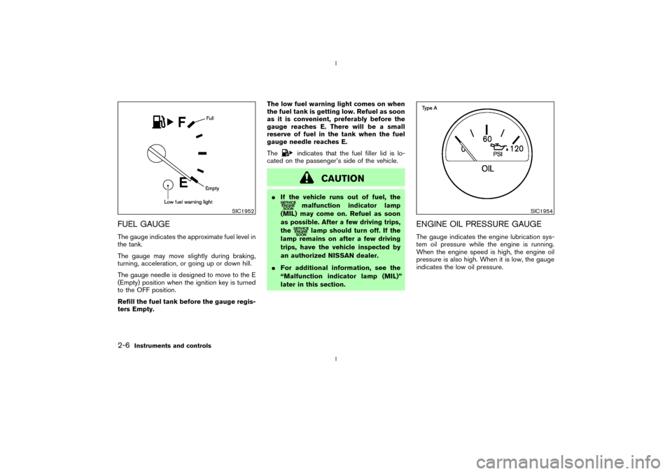
FUEL GAUGEThe gauge indicates the approximate fuel level in
the tank.
The gauge may move slightly during braking,
turning, acceleration, or going up or down hill.
The gauge needle is designed to move to the E
(Empty) position when the ignition key is turned
to the OFF position.
Refill the fuel tank before the gauge regis-
ters Empty.The low fuel warning light comes on when
the fuel tank is getting low. Refuel as soon
as it is convenient, preferably before the
gauge reaches E. There will be a small
reserve of fuel in the tank when the fuel
gauge needle reaches E.
The
indicates that the fuel filler lid is lo-
cated on the passenger's side of the vehicle.
CAUTION
IIf the vehicle runs out of fuel, the
malfunction indicator lamp
(MIL) may come on. Refuel as soon
as possible. After a few driving trips,
the
lamp should turn off. If the
lamp remains on after a few driving
trips, have the vehicle inspected by
an authorized NISSAN dealer.
IFor additional information, see the
ªMalfunction indicator lamp (MIL)º
later in this section.
ENGINE OIL PRESSURE GAUGEThe gauge indicates the engine lubrication sys-
tem oil pressure while the engine is running.
When the engine speed is high, the engine oil
pressure is also high. When it is low, the gauge
indicates the low oil pressure.
SIC1952
SIC1954
2-6
Instruments and controls
Z
02.9.13/Z33-D/V5.0
X
Page 47 of 227

TRIP COMPUTERThe display of the trip computer is situated in the
triple meter. When the ignition switch is turned
to ON, the display scrolls all the modes of the
trip computer and then shows the mode chosen
before the ignition switch is turned OFF.Switches for the trip computer are located on
the side of the combination meter panel. To
operate the trip computer, press the side of the
switches as shown above.
qA: Trip computer mode switch
qB: Trip computer setting switch
When the ignition switch is turned to ON, modes
of the trip computer can be selected by pressing
the trip computer mode switch
qA.
Each time the mode switch
qA
is pressed, the
display will change as follows:
Speed indicator®Outside air temperature
(ICY)®Distance to empty (dte)®Average fuelconsumption and speed®Elapsed time and
trip odometer®Stopwatch®Tire pressure
indicator (PSI) (if so equipped)®Up-shift indi-
cator setting (for M/T models)®Speed indica-
tor
Speed indicator (MPH or km/h)The vehicle speed is displayed in MPH or km/h
while driving.Outside air temperature (ICY Ð ÉF or
ÉC)The outside air temperature is displayed in ÉF or
ÉC in the range of þ22 to 131ÉF (þ30 to 55ÉC).
The outside air temperature mode includes a low
temperature warning feature: below 37ÉF (3ÉC),
the outside air temperature mode is automati-
cally selected and ICY indicator will illuminate in
order to draw the driver's attention. Press the
mode switch
qAif you wish to return to the mode
that was selected before the warning occurred.
The ICY indicator will continue blinking as long
as the temperature remains below 39ÉF (4ÉC).
The ambient temperature sensor is located in
front of the radiator. The sensor may be affected
by road or engine heat, wind directions and
other driving conditions. The display may differ
from the actual ambient temperature or the
SIC1956
SIC1957
2-8
Instruments and controls
Z
02.9.13/Z33-D/V5.0
X
Page 48 of 227

temperature displayed on various signs or bill-
boards.Distance to empty (dte Ð mile or km)The distance to empty (dte) mode provides you
with an estimation of the distance that can be
driven before refueling. The dte is constantly
being calculated, based on the amount of fuel in
the fuel tank and the actual fuel consumption.
The display is updated every 30 seconds.
The dte mode includes a low range warning
feature: when the fuel level is low, the dte mode
is automatically selected and the digits blink in
order to draw the driver's attention. Press the
mode switch
qAif you wish to return to the mode
that was selected before the warning occurred.
The dte indicator will remain blinking until the
vehicle is refuelled.
When the fuel level drops even lower, the dte
display will change to (----).
NOTE:
IIf the amount of fuel added while the
ignition switch is OFF is small, the dis-
play just before the ignition switch is
turned OFF may continue to be dis-
played.
IWhen driving uphill or rounding curves,
the fuel in the tank shifts, which maymomentarily change the display.
Average fuel consumption
(Mpg or l/100 km)The average fuel consumption mode shows the
average fuel consumption since the last reset.
Resetting is done by pressing the trip computer
setting switch
qB
for more than approximately 1
second. (The average speed is also reset at the
same time.)
The display is updated every 30 seconds. At
about the first 1/3 miles (500 m) after a reset,
the display shows (----).
Average speed (MPH or km/h)The average speed mode shows the average
vehicle speed since the last reset. Resetting is
done by pressing the setting switch
qB
for more
than approximately 1 second. (The average fuel
consumption is also reset at the same time.)
The display is updated every 30 seconds. The
first 30 seconds after a reset, the display shows
(----).
Elapsed time (h:m:s)The elapsed time mode shows the time since the
last reset. The displayed time can be reset by
pressing the trip computer setting switch
qB
for
more than approximately 1 second. (The tripodometer is also reset at the same time.)
Trip odometer (MLS or km)The trip odometer mode shows the total dis-
tance the vehicle has been driven since the last
reset. Resetting is done by pressing the setting
switch
qBfor more than approximately 1 second.
(The elapsed time is also reset at the same time.)
Stopwatch (h:m:s)You can use the trip computer as a stopwatch.
Each time the trip computer setting switch
qB
is
pressed, the stopwatch will be operated as
follows:
After 100 hours, the time will start from the reset
display again.
Even if the display is switched to the other mode
while the time is starting, the stopwatch contin-
ues to advance until you stop the time in the
stopwatch mode. When the ignition switch is
turned OFF, the time is reset.Tire pressure indicator (PSI) (if so
equipped)The tire pressure indicator shows tire pressure
(0 - 51 psi) of all wheels (except the spare tire)
Instruments and controls
2-9
Z
02.9.13/Z33-D/V5.0
X
Page 92 of 227
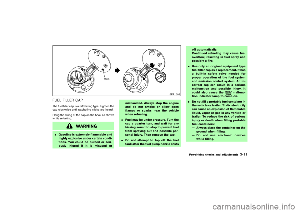
FUEL FILLER CAPThe fuel filler cap is a ratcheting type. Tighten the
cap clockwise until ratcheting clicks are heard.
Hang the string of the cap on the hook as shown
while refueling.
WARNING
IGasoline is extremely flammable and
highly explosive under certain condi-
tions. You could be burned or seri-
ously injured if it is misused ormishandled. Always stop the engine
and do not smoke or allow open
flames or sparks near the vehicle
when refueling.
IFuel may be under pressure. Turn the
cap a quarter turn, and wait for any
hissing sound to stop to prevent fuel
from spraying out and possible per-
sonal injury. Then remove the cap.
IDo not attempt to top off the fuel
tank after the fuel pump nozzle shutsoff automatically.
Continued refueling may cause fuel
overflow, resulting in fuel spray and
possibly a fire.
IUse only an original equipment type
fuel filler cap as a replacement. It has
a built-in safety valve needed for
proper operation of the fuel system
and emission control system. An in-
correct cap can result in a serious
malfunction and possible injury. It
could also cause the
malfunc-
tion indicator lamp to come on.
IDo not fill a portable fuel container in
the vehicle or trailer. Static electricity
can cause an explosion of flammable
liquid, vapor or gas in any vehicle or
trailer. To reduce the risk of serious
injury or death when filling portable
fuel containers:
Ð Always place the container on the
ground when filling.
Ð Do not use electronic devices
while filling.
SPA1509
Pre-driving checks and adjustments
3-11
Z
02.9.13/Z33-D/V5.0
X
Page 103 of 227
The air conditioning system in your NISSAN
vehicle is charged with a refrigerant designed
with the environment in mind.This refrigerant
will not harm the earth's ozone layer.How-
ever, special charging equipment and lubricant
are required when servicing your NISSAN air
conditioner. Using improper refrigerants or lubri-
cants will cause severe damage to your air
conditioning system. See ªCapacities and rec-
ommended fuel/lubricantsº in the ª9. Technical
and consumer informationº section for air con-
ditioning system refrigerant and lubricant recom-
mendations.
Your NISSAN dealer will be able to service your
environmentally friendly air conditioning system.
WARNING
The air conditioner system contains re-
frigerant under high pressure. To avoid
personal injury, any air conditioner ser-
vice should be done only by an experi-
enced technician with proper equip-
ment.Turn the ignition key to ACC or ON and press
the POWER, FM or AM button to turn on the
radio. If you listen to the radio with the engine not
running, the key should be turned to the ACC
position.
Radio reception is affected by station signal
strength, distance from radio transmitter, build-
ings, bridges, mountains and other external in-
fluences. Intermittent changes in reception qual-
ity normally are caused by these external
influences.
Using a cellular phone in or near the ve-
hicle may influence radio reception quality.
Radio receptionYour radio system is equipped with state-of-the-
art electronic circuits to enhance radio recep-
tion. These circuits are designed to extend re-
ception range, and to enhance the quality of that
reception.
However there are some general characteristics
of both FM and AM radio signals that can affect
radio reception quality in a moving vehicle, even
when the finest equipment is used. These char-
acteristics are completely normal in a given
reception area, and do not indicate any malfunc-
tion in your radio system.
Remember that a moving vehicle is not the ideal
place to listen to a radio. Because of the move-ment, reception conditions will constantly
change. Buildings, terrain, signal distance and
interference from other vehicles can work
against ideal reception. Described below are
some of the factors that can affect your radio
reception.
SERVICING AIR CONDITIONER AUDIO SYSTEM4-6
Heater, air conditioner and audio systems
Z
02.9.13/Z33-D/V5.0
X
Page 118 of 227

5 Starting and drivingPrecautions when starting and driving ............................. 5-2
Exhaust gas (Carbon monoxide) .................................. 5-2
Three way catalyst ........................................................... 5-3
Low tire pressure warning system
(if so equipped) ................................................................ 5-3
Avoiding collision and rollover ...................................... 5-4
Drinking alcohol/drugs and driving .............................. 5-5
Ignition switch ......................................................................... 5-5
Automatic transmission................................................... 5-5
Manual transmission ........................................................ 5-6
Key positions ..................................................................... 5-7
Nissan vehicle immobilizer system (NVIS)................. 5-7
Before starting the engine ................................................... 5-8
Starting the engine ................................................................ 5-8
Driving the vehicle ................................................................. 5-9
Automatic transmission................................................... 5-9
Manual transmission ..................................................... 5-12
Parking brake........................................................................ 5-14
Cruise control (if so equipped)........................................ 5-15
Precautions on cruise control .................................... 5-15Cruise control operations ............................................ 5-16
Break-in schedule ............................................................... 5-17
Increasing fuel economy .................................................... 5-17
Parking/parking on hills...................................................... 5-18
Power steering ..................................................................... 5-19
Brake system ........................................................................ 5-20
Braking precautions ...................................................... 5-20
Anti-lock brake system (ABS) .................................... 5-20
Traction control system (TCS) (if so equipped).......... 5-22
Vehicle dynamic control (VDC) system
(if so equipped) .................................................................. 5-22
Cold weather driving .......................................................... 5-24
Freeing a frozen door lock .......................................... 5-24
Anti-freeze ....................................................................... 5-24
Battery .............................................................................. 5-24
Draining of coolant water ............................................ 5-24
Tire equipment................................................................ 5-24
Special winter equipment ............................................ 5-24
Driving on snow or ice ................................................. 5-25
Engine block heater (if so equipped) ....................... 5-25
Z
02.9.13/Z33-D/V5.0
X
Page 120 of 227
d. You have had an accident involv-
ing damage to the exhaust system,
underbody, or rear of the vehicle.
THREE WAY CATALYSTThe three way catalyst is an emission control
device installed in the exhaust system. Exhaust
gases in the converter are burned at high tem-
peratures to help reduce pollutants.
WARNING
IThe exhaust gas and the exhaust sys-
tem are very hot. Keep people, ani-
mals or flammable materials away
from the exhaust system compo-
nents.
IDo not stop or park the vehicle over
flammable materials such as dry
grass, waste paper or rags. They may
ignite and cause a fire.
CAUTION
IDo not use leaded gasoline. Deposits
from leaded gasoline seriously re-
duce the three way catalyst's ability
to help reduce exhaust pollutants.
IKeep your engine tuned up. Malfunc-
tions in the ignition, fuel injection, or
electrical systems can cause overrich
fuel flow into the three way catalyst,
causing it to overheat. Do not keep
driving if the engine misfires, or if
noticeable loss of performance or
other unusual operating conditions
are detected. Have the vehicle in-
spected promptly by a NISSAN
dealer.
IAvoid driving with an extremely low
fuel level. Running out of fuel could
cause the engine to misfire, damag-
ing the three way catalyst.
IDo not race the engine while warm-
ing it up.
IDo not push or tow your vehicle to
start the engine.
LOW TIRE PRESSURE WARNING
SYSTEM (if so equipped)The low tire pressure warning system displays
pressure of all tires (except the spare tire) on the
trip computer by sending a signal from a sensor
that is installed in each wheel.
The low tire pressure warning system will acti-
vate only when the vehicle is driven at speeds
above 20 MPH (32 km/h). Also, this system may
not detect a sudden drop in tire pressure (for
example, a flat tire by catching something while
driving).
Frequently check the tire pressure indicator on
the trip computer and adjust pressure of each
tire properly. See ªTrip computerº in the ª2.
Instruments and controlsº section for the tire
pressure indicator.Flat tire warningIf the vehicle is being driven with a flat tire or
extremely low tire pressure (lower than 28 psi),
the low tire pressure warning light comes on,
and the chime sounds for about 10 seconds. On
the trip computer, the PSI indicator starts flash-
ing and the current display switches to the tire
pressure indicator.
For additional information regarding the above
warning, see ªTrip computerº and
Starting and driving
5-3
Z
02.9.13/Z33-D/V5.0
X