Page 227 of 304
227 Practical hints
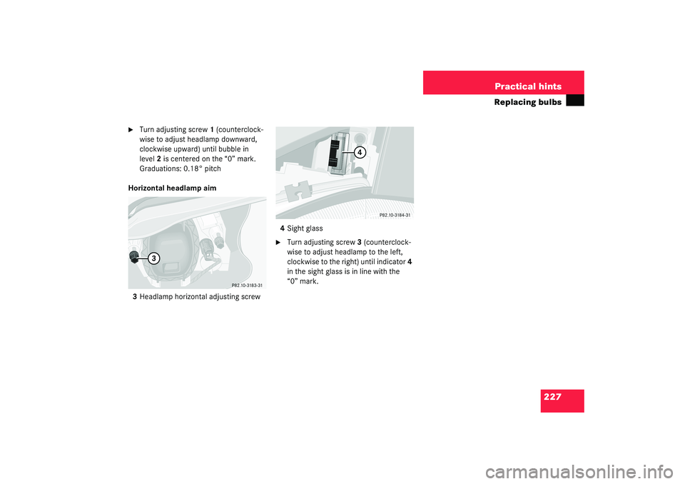
Replacing bulbs
�
Turn adjusting screw1 (counterclock-
wise to adjust headlamp downward,
clockwise upward) until bubble in
level2 is centered on the “0” mark.
Graduations: 0.18° pitch
Horizontal headlamp aim
3Headlamp horizontal adjusting screw4Sight glass
�
Turn adjusting screw3 (counterclock-
wise to adjust headlamp to the left,
clockwise to the right) until indicator4
in the sight glass is in line with the
“0” mark.
Page 228 of 304

228 Practical hintsReplacing wiper blades
Replacing wiper bladesRemoving�
Fold the wiper arm forward.
�
Press safety tab down1.
�
Push wiper blade downward2 and re-
move.Replacing wiper blade insert
�
Place wiper blade on firm support.
�
Press down both tabs.
�
Slide (in direction of arrow) the wiper
blade insert out of the retainer claws.
�
Slide (in direction of arrow) the new
wiper blade insert into retainer claws
until tabs are engaged.
Installing�
Slide wiper blade onto wiper arm until
it locks in place.
Warning!
G
For safety reasons, remove key from steer-
ing lock before replacing a wiper blade, oth-
erwise the motor could suddenly turn on and
cause injury.
!Never open the hood when the wiper
arm is folded forward.
Do not allow the wiper arms to contact
the windshield glass without a wiper
blade inserted.
Make certain that the wiper blades are
properly installed. Improperly installed
wiper blades may cause windshield
damage.
For your convenience, we recommend
that you have this work carried out by
an authorized Mercedes-Benz Center.
Page 229 of 304
 (
�page 208) or a
spare wheel with collapsible tire
(SLK 230 Kompressor and SLK 320 only)
(
�p")
229 Practical hints
Flat tire
Flat tire
Your vehicle is equipped with a TIREFIT kit
(SLK 32 AMG only) (
�page 208) or a
spare wheel with collapsible tire
(SLK 230 Kompressor and SLK 320 only)
(
�page 207).
You can identify which TIREFIT kit
(SLK 32 AMG only) you have as follows:
�
The TIREFIT container of kit 1 is a
squeeze container.
�
The TIREFIT container of kit 2 is a rigid
container and includes a flange for filler
hose (outlet) and air hose (inlet).
Preparing the vehicle�
Park the vehicle as far as possible from
moving traffic on a hard surface.
�
Turn on hazard warning flashers.
�
Engage the steering wheel lock in the
straight ahead position and set the
parking brake.
�
Move the selector lever toP (manual
transmission to first or reverse gear.
�
Have any passenger exit the vehicle at
a safe distance from the roadway.
Sealing tires with TIREFIT kit 1
Small tire punctures, only those in the
tread, can be sealed with TIREFIT.
TIREFIT can be used in ambient tempera-
tures down to -4°F (-20°C).
The TIREFIT kit stored in the trunk
(�page 208) contains the TIREFIT
container, a filler hose, a valve stem tool,
a valve core and a sticker.
�
Foreign objects (e.g. screws or nails)
should not be removed from the tire.
�
Attach the sticker where it will be easily
seen by the driver on the instrument
cluster.
Warning!
G
Keep TIREFIT away from sparks, open flame
or heat source.
Do not smoke.
Warning!
G
TIREFIT is a limited repair device. TIREFIT
cannot be used for:�
cuts or punctures larger than approx.
0.16 in (4 mm)
�
on a flat tire, or a damaged wheel
�
tire damage caused by driving with ex-
tremely low tire pressure
Do not drive the vehicle under such circum-
stances.
Contact your nearest Mercedes-Benz
Center for assistance or call Roadside Assis-
tance.
Page 232 of 304

232 Practical hintsFlat tireInflating the tire
1Flap
2Air hose with pressure gauge and vent
screw
3Union nut
4Electrical plug
�
Open flap1 on air pump.
�
Pull out electrical plug4 and air hose
with pressure gauge2.
�
Screw union nut3 with air hose2 on to
the tire valve.
�
Insert electrical plug4 into vehicle
cigarette lighter socket.
�
Turn key in steering lock to position1
(�page 29).
�
PressI on the electric air pump switch.
The electric air pump should now
switch on and inflate the tire.
After 5 minutes, the pressure gauge must
display at least 26 psi (1.8 bar). The air
hose and the union nut can become hot
during inflation. Please exercise appropri-
ate caution.
�
If this tire pressure is not attained, turn
off the electric air pump, detach the air
hose from the tire valve, and again
drive vehicle back and forth very slowly
approximately 30 ft (10 m).
This serves to better distribute the
TIREFIT sealant material inside the tire.
�
Inflate the tire again.
�
Press0 on the electric air pump
switch.
�
Turn key in steering lock to position0.
The electric air pump should now be
switched off.
Warning!
G
Observe safety instructions on air pump la-
bel.
!Do not exceed the maximum pressure
of 36 psi (2.5 bar).
!Do not operate the electric air pump
longer than eight minutes without in-
terruption. Otherwise it may overheat.
You may operate the air pump again af-
ter it has cooled off.
��
Page 236 of 304

236 Practical hintsFlat tire�
Unscrew the valve cap from tire
valve7.
�
Screw filler hose10 onto tire valve7.
�
Insert electrical plug4 into vehicle cig-
arette lighter socket.
�
Turn key in steering lock to position1
(�page 29).
�
PressI on electric air pump switch8.
The electric air pump should now
switch on and inflate the tire.After 5 minutes, the pressure gauge must
display at least 26 psi (1.8 bar). The air
hose can become hot during inflation.
Please exercise appropriate caution.
�
If this tire pressure is not attained, turn
off the electric air pump, detach the fill-
er hose from the tire valve, and drive
vehicle back and forth very slowly ap-
proximately 30 ft (10 m).
This serves to better distribute the
TIREFIT sealant material inside the tire.
�
Unscrew the air pump’s air hose5 from
flange6 of the TIREFIT container.
�
Inflate the tire again.
�
After attaining a tire pressure of 26 psi
(1.8 bar), press0 on electric air pump
switch8.
The electric air pump should now be
switched off.
�
Turn key in steering lock to position0
(�page 29).
!Do not operate the electric air pump
longer than eight minutes without in-
terruption. Otherwise it may overheat.
You may operate the air pump again af-
ter it has cooled off.
��
Warning!
G
If a tire pressure of 26 psi (1.8 bar) is not at-
tained, tire is too severely damaged for
TIREFIT to provide a reliable tire repair.
In this case, TIREFIT cannot properly seal
the tire.
Do not drive the vehicle.
Contact the nearest Mercedes-Benz Center
or call Roadside Assistance.
Page 238 of 304

238 Practical hintsFlat tire�
Visit an authorized Mercedes-Benz
Center as soon as possible to obtain a
new TIREFIT kit.
�
Bring used TIREFIT materials to an au-
thorized Mercedes-Benz Center for
proper disposal.
�
Replace your TIREFIT container every
four years. Replacement containers are
available at your authorized
Mercedes-Benz Center.
Mounting the spare wheel
More information on spare wheels with
collapsible tires can be found in the “Tech-
nical data” section (
�page 265).Preparing the vehicle
Prepare the vehicle as described under
“Preparing the vehicle” on page
(
�page 229).
�
Turn pump holder counterclockwise to
loosen (
�page 207).
�
Take the spare wheel out of wheel well.
Lifting the vehicle
�
Prevent the vehicle from rolling away
by blocking wheels with wheel chocks
(not included) or other sizable objects.
When changing wheel on a level surface:
�
Place one chock in front of and one be-
hind the wheel that is diagonally oppo-
site to the wheel being changed.
When changing wheel on a hill:
�
Place chocks on the downhill side
blocking both wheels of the other axle.
�
Take the vehicle tool kit and the jack
out of the trunk.
Warning!
G
Do not exceed vehicle speed of 50 mph
(80 km/h). A TIREFIT repair is not designed
to operate at higher speeds.
The sticker must be attached on the instru-
ment cluster where it will be easily seen by
the driver.
Vehicle handling characteristics may
change. Adapt your driving accordingly.
Warning!
G
The dimensions of the spare wheel are dif-
ferent from those of the road wheels. As a
result, the vehicle handling characteristics
change when driving with a spare wheel
mounted. Adapt your driving style accord-
ingly.
The spare wheel is for temporary use only.
When driving with spare wheel mounted, en-
sure proper tire pressure and do not exceed
vehicle speed of 50 mph (80 km/h).
Drive to the nearest Mercedes-Benz Center
as soon as possible to have the spare wheel
replaced with a regular road wheel.
Never operate the vehicle with more than
one spare wheel mounted.
��
Page 239 of 304
.
The jack support tubes are located behind
the f")
239 Practical hints
Flat tire
�
On whee l to b e change d, loos en b ut do
not yet remove the wheel bolts (ap-
proximately one full turn with wrench).
The jack support tubes are located behind
the front wheel housings and in front of the
rear wheel housings.1Jack tube cover
2Notch
�
Carefully insert the screwdriver (sup-
plied in the tool kit) into notch2.
�
Pry out cover1 just so far as you can
place your fingers underneath the cov-
er.
�
Carefully pull out cover1 completely.
Make sure that the pins do not brake
off.
The cover will be hanging from a plastic
band attached to it.
Warning!
G
The jack is designed exclusively for jacking
up the vehicle at the jack tubes built into
both sides of the vehicle. To help avoid per-
sonal injury, use the jack only to lift the ve-
hicle during a wheel change. Never get
beneath the vehicle while it is supported by
the jack. Keep hands and feet away from the
area under the lifted vehicle. Always firmly
set parking brake and block wheels before
raising vehicle with jack.
Do not disengage parking brake while the
vehicle is raised. Be certain that the jack is
always vertical (plumb line) when in use, es-
pecially on hills. Always try to use the jack
on level surface. Make sure that the jack
arm is fully inserted in the jack tube. Always
lower the vehicle onto sufficient capacity
jackstands before working under the vehi-
cle.
��
Page 240 of 304

240 Practical hintsFlat tire3Jacking pin
4Jack support tube hole
5Crank
6Small platform
7Large platform�
Fold out jacking pin3 in direction of
arrowA until it snaps into place.
The green marking on the jacking pin
should now form one line with the
marking on the jack.
�
Insert jacking pin3 in direction of
arrowB fully into jack support tube
hole4.
�
Keeping jack in this position, turn
crank5 clockwise until the jack’s small
platform6 meets the ground. Make
sure that the jack is always vertical
(plumb line).
�
Jack the vehicle until the wheel is a
maximum of 1.2 in (3 cm) from the
ground.
The jack is now standing on large
platform7.
Never start engine while vehicle is
raised.Removing the wheel
1Alignment bolt
�
Unscrew upper-most wheel bolt and re-
move.
�
Replace this wheel bolt with alignment
bolt1 supplied in the tool kit.
�
Remove the remaining bolts.
Warning!
G
Insert the jack arm fully into the jack sup-
port tube hole up to the stop. Otherwise the
vehicle may fall from the jack and cause per-
sonal injury or damage to the vehicle.
!Do not place wheel bolts in sand or dirt.
This could result in damage to the bolt
and wheel hub threads.
��