Page 211 of 304

211 Practical hints
Unlocking/locking in an emergency
Locking the vehicle
If you are unable to lock the vehicle with
the remote control, lock it with the key as
follows:�
Close the passenger door and the
trunk.
�
Press the central locking switch in the
upper center console (
�page 79).
�
Check to see whether the locking knob
on the passenger door is still visible. If
necessary, push it down manually.
�
Lock the driver’s door with the key. To
do so, push key into the lock until it
stops and turn it to the right2
(�page 210).
�
Lock the trunk, if necessary with the
key. To do so, push key into the trunk
lid lock until it stops.
Turn the key clockwise to position3
(�page 210).
!Do not place the key inside the trunk,
since the trunk is locked once its lid is
closed and the vehicle was previously
centrally locked.iUnlocking your vehicle with the key will
trigger the anti-theft alarm system. To
cancel the alarm, do one of the follow-
ing:�
Press button
Œ
or
‹
on the
remote control.
�
Insert the key in the steering lock
and turn it to position1.
iUsing the key does not operate the
central locking system.
Page 215 of 304

215 Practical hints
Opening/closing in an emergency
Opening/closing in an emergency
Raising retractable hardtop manually
If the retractable hardtop cannot be closed
automatically, make certain that all points
listed under the “Retractable hardtop” sec-
tion (
�page 129) were observed.
If the automatic operation still does not
function properly, you can close the re-
tractable hardtop manually.
This procedure should be performed with
great care by two persons.
�
Open doors or lower windows
(�page 127).
�
Set parking brake (
�page 47).
�
Remove key from steering lock
(�page 29).
�
Open trunk lid (
�page 77).
�
Open the right side trim panel in the
trunk.1Screw of hydraulic pump
2Control cable, right
3Hex-socket wrench
�
Remove hex-socket wrench3 from
cover.
�
Using wrench3 turn screw1 of the
hydraulic pump counterclockwise as
far as it will go.
!Manually closing the retractable hard-
top is a complicated and technically de-
manding procedure. Close the
retractable hardtop manually in emer-
gency cases only. Otherwise, visit an
authorized Mercedes-Benz Center.
Warning!
G
�
It is important that a second person
helps you. Otherwise, you could become
trapped or injured.
�
Remove any wristwatches or jewelry
such as rings or bracelets. Otherwise,
they could get caught in the vehicle
mechanism, causing personal injury to
yourself or damage to the vehicle.
�
Always use the grips provided. Other-
wise you could injure yourself.
��
Page 219 of 304
219 Practical hints
Opening/closing in an emergency
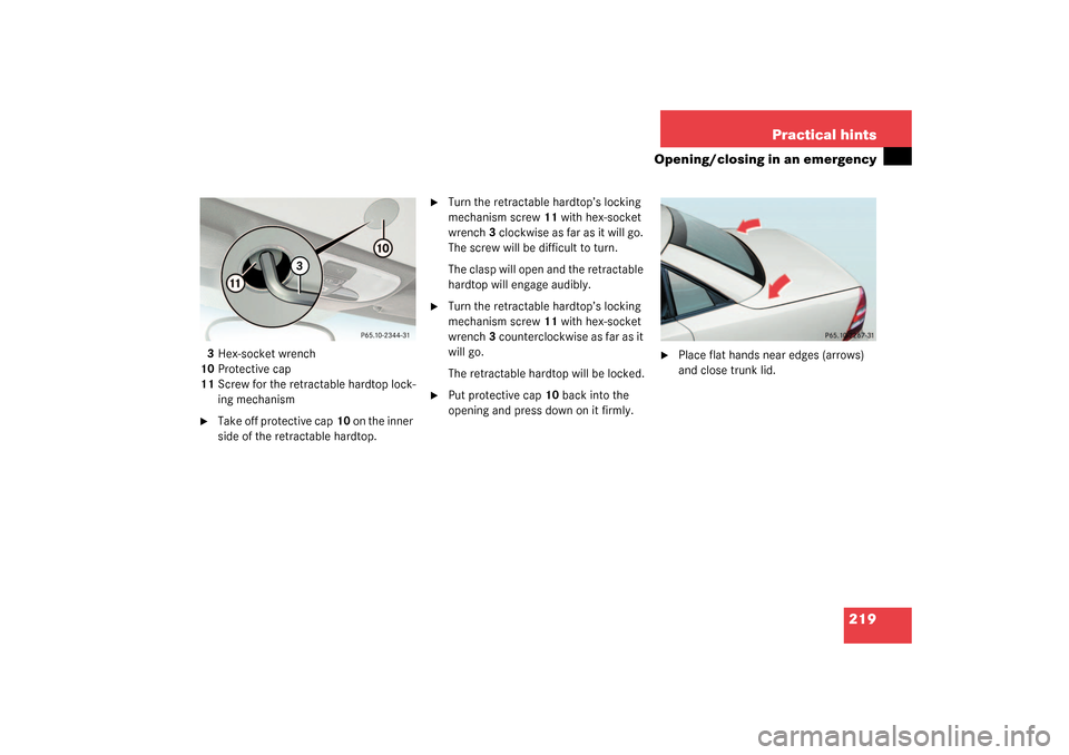
3Hex-socket wrench
10Protective cap
11Screw for the retractable hardtop lock-
ing mechanism�
Take off protective cap10 on the inner
side of the retractable hardtop.
�
Turn the retractable hardtop’s locking
mechanism screw11 with hex-socket
wrench3 clockwise as far as it will go.
The screw will be difficult to turn.
The clasp will open and the retractable
hardtop will engage audibly.
�
Turn the retractable hardtop’s locking
mechanism screw11 with hex-socket
wrench3 counterclockwise as far as it
will go.
The retractable hardtop will be locked.
�
Put protective cap10 back into the
opening and press down on it firmly.
�
Place flat hands near edges (arrows)
and close trunk lid.
Page 224 of 304
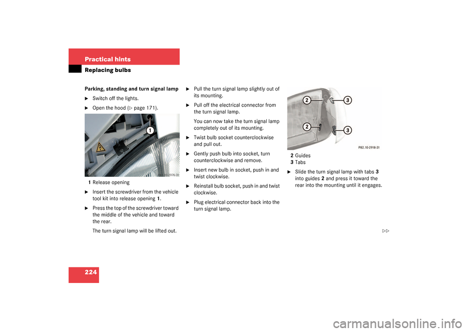
224 Practical hintsReplacing bulbsParking, standing and turn signal lamp�
Switch off the lights.
�
Open the hood (
�page 171).
1Release opening
�
Insert the screwdriver from the vehicle
tool kit into release opening1.
�
Press the top of the screwdriver toward
the middle of the vehicle and toward
the rear.
The turn signal lamp will be lifted out.
�
Pull the turn signal lamp slightly out of
its mounting.
�
Pull off the electrical connector from
the turn signal lamp.
You can now take the turn signal lamp
completely out of its mounting.
�
Twist bulb socket counterclockwise
and pull out.
�
Gently push bulb into socket, turn
counterclockwise and remove.
�
Insert new bulb in socket, push in and
twist clockwise.
�
Reinstall bulb socket, push in and twist
clockwise.
�
Plug electrical connector back into the
turn signal lamp.2Guides
3Tabs
�
Slide the turn signal lamp with tabs3
into guides2 and press it toward the
rear into the mounting until it engages.
��
Page 225 of 304

225 Practical hints
Replacing bulbs
Side marker lamp bulb�
Switch off the lights.
�
Carefully slide lamp towards front.
�
Remove rear end first.
�
Twist bulb socket counterclockwise
and pull out.
�
Gently push bulb into socket, turn
counterclockwise and remove.
�
Insert new bulb in socket, push in and
twist clockwise.
�
Reinstall bulb socket, push in and twist
clockwise.
�
To reinstall lamp, set rear end in
bumper and let front end snap into
place.
Replacing bulbs for rear lamps
Tail lamp assemblies
1Brake lamp
2Turn signal lamp
3Tail, parking and standing lamp, side
marker
4Backup lamp
5Rear fog lamp (driver’s side)
�
Switch off the lights.
�
Open trunk lid (
�page 77).
�
Remove cover in right side panel.
�
Remove first aid kit (
�page 206).
Remove cover in left side panel.
�
Turn bulb socket counterclockwise and
pull out.
�
Gently push bulb into socket, turn
counterclockwise and remove.
�
Insert new bulb in socket, push in and
turn clockwise.
�
Reinstall bulb socket, push in and turn
clockwise.
�
Close cover.
Page 227 of 304
227 Practical hints
Replacing bulbs
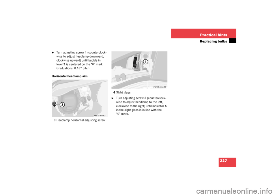
�
Turn adjusting screw1 (counterclock-
wise to adjust headlamp downward,
clockwise upward) until bubble in
level2 is centered on the “0” mark.
Graduations: 0.18° pitch
Horizontal headlamp aim
3Headlamp horizontal adjusting screw4Sight glass
�
Turn adjusting screw3 (counterclock-
wise to adjust headlamp to the left,
clockwise to the right) until indicator4
in the sight glass is in line with the
“0” mark.
Page 238 of 304

238 Practical hintsFlat tire�
Visit an authorized Mercedes-Benz
Center as soon as possible to obtain a
new TIREFIT kit.
�
Bring used TIREFIT materials to an au-
thorized Mercedes-Benz Center for
proper disposal.
�
Replace your TIREFIT container every
four years. Replacement containers are
available at your authorized
Mercedes-Benz Center.
Mounting the spare wheel
More information on spare wheels with
collapsible tires can be found in the “Tech-
nical data” section (
�page 265).Preparing the vehicle
Prepare the vehicle as described under
“Preparing the vehicle” on page
(
�page 229).
�
Turn pump holder counterclockwise to
loosen (
�page 207).
�
Take the spare wheel out of wheel well.
Lifting the vehicle
�
Prevent the vehicle from rolling away
by blocking wheels with wheel chocks
(not included) or other sizable objects.
When changing wheel on a level surface:
�
Place one chock in front of and one be-
hind the wheel that is diagonally oppo-
site to the wheel being changed.
When changing wheel on a hill:
�
Place chocks on the downhill side
blocking both wheels of the other axle.
�
Take the vehicle tool kit and the jack
out of the trunk.
Warning!
G
Do not exceed vehicle speed of 50 mph
(80 km/h). A TIREFIT repair is not designed
to operate at higher speeds.
The sticker must be attached on the instru-
ment cluster where it will be easily seen by
the driver.
Vehicle handling characteristics may
change. Adapt your driving accordingly.
Warning!
G
The dimensions of the spare wheel are dif-
ferent from those of the road wheels. As a
result, the vehicle handling characteristics
change when driving with a spare wheel
mounted. Adapt your driving style accord-
ingly.
The spare wheel is for temporary use only.
When driving with spare wheel mounted, en-
sure proper tire pressure and do not exceed
vehicle speed of 50 mph (80 km/h).
Drive to the nearest Mercedes-Benz Center
as soon as possible to have the spare wheel
replaced with a regular road wheel.
Never operate the vehicle with more than
one spare wheel mounted.
��
Page 240 of 304

240 Practical hintsFlat tire3Jacking pin
4Jack support tube hole
5Crank
6Small platform
7Large platform�
Fold out jacking pin3 in direction of
arrowA until it snaps into place.
The green marking on the jacking pin
should now form one line with the
marking on the jack.
�
Insert jacking pin3 in direction of
arrowB fully into jack support tube
hole4.
�
Keeping jack in this position, turn
crank5 clockwise until the jack’s small
platform6 meets the ground. Make
sure that the jack is always vertical
(plumb line).
�
Jack the vehicle until the wheel is a
maximum of 1.2 in (3 cm) from the
ground.
The jack is now standing on large
platform7.
Never start engine while vehicle is
raised.Removing the wheel
1Alignment bolt
�
Unscrew upper-most wheel bolt and re-
move.
�
Replace this wheel bolt with alignment
bolt1 supplied in the tool kit.
�
Remove the remaining bolts.
Warning!
G
Insert the jack arm fully into the jack sup-
port tube hole up to the stop. Otherwise the
vehicle may fall from the jack and cause per-
sonal injury or damage to the vehicle.
!Do not place wheel bolts in sand or dirt.
This could result in damage to the bolt
and wheel hub threads.
��