Page 19 of 376
19 At a glance
Cockpit
Item
Page
1
Parking brake pedal
41
2
Hood lock release
227
3
Parking brake release
47
4
Door control panel
26
5
Exterior lamp switch
43,
102
6
Headlamp washer switch
146
7
Combination switch�
Turn signals
�
Windshield wipers
�
High beam
43
44
104
8
Cruise control switch�
Cruise control
�
Distronic*
168
171
9
Instrument cluster
20,
108
10
Multifunction steering
wheel
22,
111
11
Lever for voice control
system, see separate
operating instructions
12
Front Parktronic* warn-
ing indicator
186
13
Digital clock
122
14
Overhead control panel
25
15
Interior storage compart-
ments (locking/unlock-
ing)
194
16
7
indicator lamp
64
17
Glove box
190
18
Center console
23, 24
19
Starter switch
31
20
Horn
21
Steering wheel adjust-
ment stalk
Heated steering wheel*
34
197
Item
Page
Page 108 of 376
.
The instrument")
108 Controls in detailInstrument cluster
Instrument clusterA full view illustration of the instrument
cluster can be found in the “At a glance”
section of this manual (
�page 20).
The instrument cluster is activated when
you:
�
open a door
�
turn on the ignition
�
press the reset knob (
�page 20)
�
switch on the exterior lamps
Only opening a door will activate the in-
strument cluster for approximately
30 seconds.
You can change the instrument cluster set-
tings in the Instrument cluster submenu of
the control system (
�page 122).
Instrument cluster illumination
Use the reset knob to adjust the illumina-
tion brightness for the instrument cluster
and the switches on the center console.
To brighten illumination�
Turn the reset knob in the instrument
cluster (
�page 20) clockwise.
The instrument cluster illumination will
brighten.To dim illumination
�
Turn the reset knob in the instrument
cluster (
�page 20) counterclockwise.
The instrument cluster illumination will
dim.
Coolant temperature gauge
Under normal driving conditions, the cool-
ant temperature may rise to 248°F
(120°C). The coolant temperature may
rise to 266°F (130°C) at high outside tem-
peratures or when driving in hilly terrain.
The engine should not be operated with
the coolant temperature above 266°F
(130°C). Doing so may cause serious en-
gine damage which is not covered by the
Mercedes-Benz Limited Warranty.
iThe instrument cluster illumination is
dimmed or brightened to suit ambient
light conditions.
Page 122 of 376

122 Controls in detailControl systemInstrument cluster submenu
Access the
Inst. cluster
menu via the
Settings
menu. Use the
Inst. cluster
submenu to change the instrument cluster
display settings. The following functions
are available:Selecting time display mode
�
Move the selection marker with the æ
or
ç
button to the
Inst.
cluster
submenu.
�
Press button
j
or
k
repeatedly
until you see this message in the left
display:
Clock
.
The selection marker is on the current
setting.
�
Press
æ
or
ç
to set the
12-hour
or
24-hour
time display mode.Selecting temperature display mode
�
Move the selection marker with button æ
or
ç
to the
Inst. cluster
submenu.
�
Press button
j
or
k
repeatedly
until you see this message in the left
display:
Temp. indicator
.
The selection marker is on the current
setting.
�
Press
æ
or
ç
to set temperature
unit to degrees Celsius (
°C) or degrees
Fahrenheit (
°F).
Function
Page
Select time display mode
122
Select temperature display
mode
122
Select speedometer display
mode
123
Select language
123
Page 291 of 376

291 Practical hints
Locking/unlocking in an emergency
Unlocking the trunk
If you are unable to unlock the trunk with
the key, open the trunk with the mechani-
cal key as follows:Trunk lid lock1Unlocking�
Insert the mechanical key into the
trunk lid lock.
�
Perform the following two steps simul-
taneously:�
Turn the key counterclockwise to
position 1.
�
Pull the trunk lid handle and lift lid.Unlocking interior storage compart-
ments
Locking storage areas in the passenger
compartment include:
�
the glove box
�
the storage space under the armrest
�
the rear storage compartments
If these cannot be unlocked by means of
the key, the KEYLESS-GO* card or the cen-
tral locking button, use the mechanical key
to open the glove box.1Separately unlock storage compart-
ments
2Centrally lock/unlock storage com-
partments
3Separately lock storage compartments
�
Slide mechanical key out of key hous-
ing (
�page 290).
�
Insert the mechanical key into the
glove box lock and turn it to position 2.
All storage compartments are now un-
locked.
iThe storage space under the armrest
and the rear storage compartments
can only be unlocked using the me-
chanical key at the glove box lock.
Page 298 of 376
. Do not remove.
3High beam lamp coverReplacing fron")
298 Practical hintsReplacing bulbsReplacing bulbs for front lamps
1Bulb socket for turn signal lamp
2Low beam lamp cover (Xenon or
Bi-Xenon* lamp). Do not remove.
3High beam lamp coverReplacing front turn signal bulb
�
Switch off the lights.
�
Open the hood (
�page 227).
�
Twist bulb socket 1 counterclockwise
and pull out.
�
Push bulb into socket, turn counter-
clockwise and remove.
�
Insert new bulb in socket, push and
twist clockwise.
�
Reinsert bulb socket in lamp and twist
clockwise.Replacing high beam bulbs
1High beam bulbs
2Locking mechanism
3Parking and standing lamps
�
Switch off the lights.
�
Open the hood (
�page 227).
�
Press ends of headlamp cover tab to-
gether and remove cover.
�
Pull electrical connector off.
�
Turn the locking mechanism 2 counter-
clockwise and take out the bulb.
�
Insert the new bulb so that the base lo-
cates in the recess on the holder.
Warning!
G
Do not remove the cover for the Xenon or
Bi-Xenon*headlamp. Because of high volt-
age in Xenon and Bi-Xenon* lamps, it is dan-
gerous to replace the bulb or repair the lamp
and its components. We recommend that
you have such work done by a qualified
technician.
Page 299 of 376

299 Practical hints
Replacing bulbs
�
Turn the locking mechanism 2 clock-
wise.
�
Plug the connector onto the bulb.
�
Align headlamp cover and click into
place.
Replacing parking and standing lamp
bulbs
�
Switch off the lights.
�
Open the hood (
�page 227).
�
Press ends of headlamp cover tab to-
gether and remove cover.
�
Pull out the bulb socket with the bulb.
�
Pull the bulb out of the bulb socket.
�
Insert a new bulb in the socket.
�
Reinstall the bulb socket.
�
Align headlamp cover and click into
place.Replacing side marker lamp
�
Switch off the lights.
�
Carefully slide lamp towards rear.
�
Remove front end first.
�
Twist bulb socket counterclockwise
and pull out.
�
Pull bulb out of the bulb socket.
�
Insert new bulb in socket.
�
Reinstall bulb socket, push in, and twist
clockwise.
�
To reinstall lamp, set rear end in
bumper and let front end snap into
place.
Replacing bulbs for rear lamps
Tail lamp assemblies
1Backup lamp
2Turn signal lamp
3Driver’s side: Rear fog lamp
Passenger’s side: Substitute lamp�
Switch off the lights.
�
Open the trunk lid (
�page 83).
�
Fold trim to side and remove.
�
Twist bulb socket counterclockwise
and pull out.
iHave the headlamp adjustment
checked regularly.
��
Page 300 of 376
300 Practical hintsReplacing bulbs�
Gently push bulb into socket, turn
counterclockwise and remove.
�
Insert new bulb and reinstall bulb sock-
et.
The bulb socket should audibly click
into place.
�
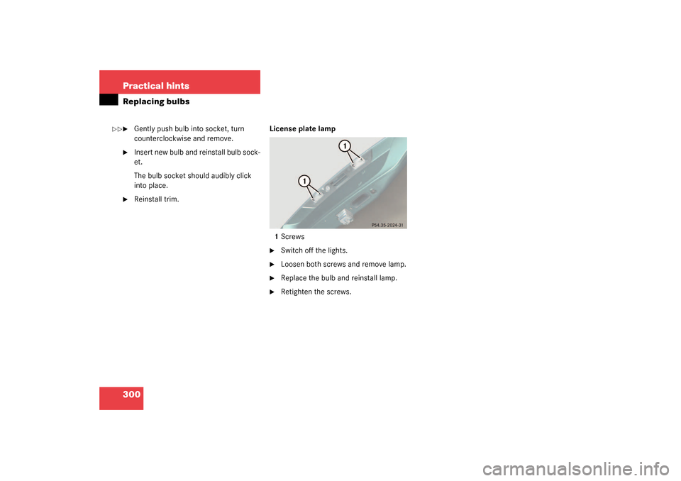
Reinstall trim.License plate lamp
1Screws
�
Switch off the lights.
�
Loosen both screws and remove lamp.
�
Replace the bulb and reinstall lamp.
�
Retighten the screws.
��
Page 312 of 376
.
�
Turn spare wheel bracket counter-
clockwise to loosen.
�
Take the whe")
312 Practical hintsFlat tireMounting the spare wheel Preparing the vehicle
Prepare the vehicle as described above
(
�page 302).
�
Turn spare wheel bracket counter-
clockwise to loosen.
�
Take the wheel out of the trunk.
Lifting the vehicle
�
Prevent the vehicle from rolling away
by blocking wheels with wheel chocks
(not included) or other sizable objects.
When changing wheel on a level sur-
face:�
Place one chock in front of and one
behind the wheel that is diagonally
opposite to the wheel being
changed.
When changing wheel on a hill:
�
Place chocks on the downhill side
blocking both wheels of the other
axle.
�
Take the vehicle tool kit and the jack
out of the storage compartment under
the trunk floor (
�page 289).
Warning!
G
The dimensions of the spare wheel are dif-
ferent from those of the road wheels. As a
result, the vehicle handling characteristics
change when driving with a mounted spare
wheel. Adapt your driving style accordingly.
The spare wheel is for temporary use only.
When driving with spare wheel mounted, en-
sure proper tire pressure and do not exceed
vehicle speed of 50 mph (80 km/h).
Drive to the nearest Mercedes-Benz Center
as soon as possible to have the spare wheel
replaced with a regular road wheel.
Never operate the vehicle with more than
one spare wheel mounted.
Warning!
G
The jack is designed exclusively for jacking
up the vehicle at the jack tubes built into
both sides of the vehicle. To help avoid per-
sonal injury, use the jack only to lift the ve-
hicle during a wheel change. Never get
beneath the vehicle while it is supported by
the jack. Keep hands and feet away from the
area under the lifted vehicle. Always firmly
set parking brake and block wheels before
raising vehicle with jack.
Do not disengage parking brake while the
vehicle is raised. Be certain that the jack is
always vertical (plumb line) when in use, es-
pecially on hills. Always try to use the jack
on level surface. Be sure that the jack arm is
fully inserted in the jack tube. Always lower
the vehicle onto sufficient capacity jack-
stands before working under the vehicle.