Page 73 of 376

73 Safety and Security
Driving safety systems
The SBC brake system is automatically ac-
tivated when you:�
unlock the vehicle with the key or the
KEYLESS-GO* card
�
open the driver’s or passenger door
�
turn the key in the starter switch to
position1
�
in vehicles with KEYLESS-GO*, press
start/stop button on selector lever
once
�
depress the brake pedal
�
release the parking brake
Warning!
G
The SBC brake system requires electrical
power to operate.
A malfunction in the vehicle’s power supply
or electrical system may impair brake sys-
tem operation and switch it into its emer-
gency operation mode. In such a case, the
red brake warning lamp (
�page 253) and
the warning messages (
�page 265) light up
while driving. To brake, the driver must then
apply significantly greater brake pedal pres-
sure and depress the pedal much further to
obtain the expected braking effect. If neces-
sary, apply full pressure to the brake pedal.
Brakes are only applied to the front wheels.
Stopping distance is increased!
If there is a malfunction in the SBC brake
system, we recommend that the vehicle be
transported with all wheels off the ground
using flatbed or appropriate wheel lift/dolly
equipment.
A tow bar must be used if circumstances
do not permit the use of the recommended
towing methods and the vehicle requires
towing with all four wheels on the ground.
Towing the vehicle with all four wheels on
the ground is only permissible for distances
up to 30 miles (50 km) and at a speed not
to exceed 30 mph (50 km/h). For more in-
formation, refer to “Towing the vehicle”
(�page 325).
iIf the SBC brake system is activated as
the brake pedal is first depressed, you
may feel a reduced pedal resistance
and longer pedal travel than normal.
When releasing the pedal, you may also
feel the brake pedal pulsate and you
may hear a sound which is caused by
the activation of the SBC pump. This is
normal and not an indication of a mal-
function. Pedal travel returns to normal
when you release the brake pedal and
the sound soon ceases.
Page 99 of 376

99 Controls in detail
Memory function
Memory function
With the memory switch you can store up
to three different settings per key and KEY-
LESS-GO* card.
The following settings are saved for each
stored position:�
Driver’s seat and backrest position
�
Steering wheel position
�
Inside rear view mirror position
�
Driver’s side exterior rear view mirror
position
�
Passenger side exterior rear view mir-
ror position
These key dependent memory settings can
be deactivated if desired (
�page 130).The memory switch is located on the door.
MMemory button
1, 2, 3Stored positions
�
Be sure that the ignition is switched on
or one door is open.
All the lamps in the instrument cluster
light up when the ignition is switched
on.
!Prior to operating the vehicle, the driv-
er should check and adjust the seat
height, seat position fore and aft, and
seat backrest angle if necessary, to en-
sure adequate control, reach and com-
fort. The head restraint should also be
adjusted for proper height. Also see air-
bag section (
�page 53) for proper seat
positioning.
In addition, adjust the steering wheel to
ensure adequate control, reach, opera-
tion and comfort. Both the inside and
outside rear view mirrors should be ad-
justed for adequate rear vision.
Fasten seat belts. Infants and small
children should be seated in a properly
secured restraint system that complies
with U.S. Federal Motor Vehicle Safety
Standard 213 and Canadian Motor Ve-
hicle Safety Standard 213.
Warning!
G
Do not activate the memory function while
driving. Activating the memory function
while driving could cause the driver to lose
control of the vehicle.
Page 102 of 376
102 Controls in detailLighting
LightingFor notes on how to switch on the head-
lamps and use the turn signals, see the
“Getting started” section (
�page 43).
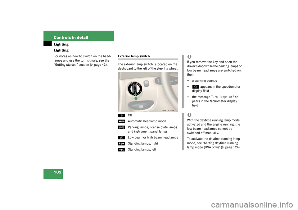
Exterior lamp switch
The exterior lamp switch is located on the
dashboard to the left of the steering wheel.M
Off
U
Automatic headlamp mode
C
Parking lamps, license plate lamps
and instrument panel lamps
B
Low beam or high beam headlamps
ˆ
Standing lamps, right
‚
Standing lamps, left
iIf you remove the key and open the
driver’s door while the parking lamps or
low beam headlamps are switched on,
then �
a warning sounds
�
$
appears in the speedometer
display field
�
the message
Turn lamps off
ap-
pears in the tachometer display
field
iWith the daytime running lamp mode
activated and the engine running, the
low beam headlamps cannot be
switched off manually.
To activate the daytime running lamp
mode, see “Setting daytime running
lamp mode (USA only)” (
�page 124).
Page 103 of 376

103 Controls in detail
Lighting
Manual headlamp mode
The low beam headlamps and parking
lamps can be switched on or off with the
exterior lamp switch.
Automatic headlamp mode
The parking lamps, low beam headlamps
and license plate lamps switch on and off
automatically depending on the brightness
of the ambient light.
�
Turn the exterior lamp switch to
U
.Daytime running lamp mode
�
Turn exterior lamp switch to
position
M
or
U
.
When the engine is running, the low
beam headlamps are automatically
switched on. In low ambient light con-
ditions the parking lamps will also
switch on.
Canada only:
When you shift from a driving position to
positionN orP, the low beam switches off
(3 minutes delay).
For nighttime driving you should turn the
exterior lamp switch to position
B
to
permit activation of the high beam head-
lamps.
Warning!
G
In automatic headlamp mode, the head-
lamps will not be automatically switched on
under foggy conditions. To minimize risk to
you and to others, activate headlamps by
turning exterior lamp switch to
B
.
The driver is responsible for the operation of
the vehicle’s lights at all times. The automat-
ic headlamp feature is only an aid to the driv-
er. Switch on the vehicle lights manually
when driving or when traffic conditions re-
quire you to do so.
iWith the daytime running lamp mode
activated, the low beam headlamps will
not be switched off automatically.iFront fog lamps and rear fog lamp can
not be switched on manually with exte-
rior lamp switch in position
U
. To
activate the fog lamps turn exterior
lamp switch to position
B
.
iIf you drive in countries where vehicles
drive on the other side of the road than
the country where the vehicle is regis-
tered, you must have the headlamps
modified for symmetrical low beams.
Relevant information can be obtained
at your authorized Mercedes-Benz Cen-
ter.
Page 105 of 376
105 Controls in detail
Lighting
High beam flasher �
Pull the combination switch briefly in
direction2.
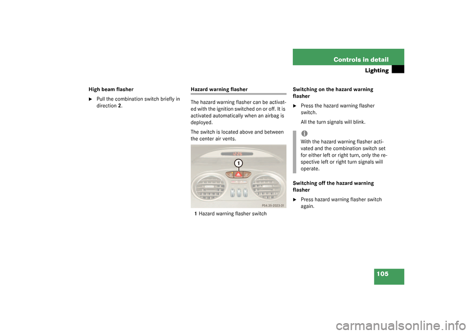
Hazard warning flasher
The hazard warning flasher can be activat-
ed with the ignition switched on or off. It is
activated automatically when an airbag is
deployed.
The switch is located above and between
the center air vents.
1Hazard warning flasher switchSwitching on the hazard warning
flasher
�
Press the hazard warning flasher
switch.
All the turn signals will blink.
Switching off the hazard warning
flasher
�
Press hazard warning flasher switch
again.iWith the hazard warning flasher acti-
vated and the combination switch set
for either left or right turn, only the re-
spective left or right turn signals will
operate.
Page 119 of 376
.
Should any malfunct")
119 Controls in detail
Control system
The stored messages will now be displayed
in order. See the “Practical hints” section
for malfunction and warning messages
(�page 257).
Should any malfunctions occur while driv-
ing, the number of malfunctions will reap-
pear in the right display field when the key
in the starter switch is turned to position0
or removed from the starter switch.
Settings menu
In the
Settings
menu there are two func-
tions:
�
The function
Reset to factory set-
tings using reset button
, with which
you can reset all the settings to those
set at the factory.
�
A collection of submenus with which
you can make individual settings for
your vehicle.
�
Press button
è
or
ÿ
repeatedly
until the
Settings...
menu is seen in
the left display.The following settings and submenus are
available:
iThe message memory will be cleared
when you turn the key in the starter
switch to position1 or2. You will then
only see Priority 1 malfunctions
(�page 257).
Function
Page
Resetting all settings
120
Submenus in the Settings menu
120
Resetting the functions of a sub-
menu
120
Instrument cluster submenu
122
Lighting submenu
124
Vehicle submenu
127
Convenience submenu
129
Page 145 of 376
 and for setting the rear view
mirrors (
�page 35) is found in the “Get-
ting started” secti")
145 Controls in detail
Good visibility
Good visibility
Information on the windshield wipers
(�page 44) and for setting the rear view
mirrors (
�page 35) is found in the “Get-
ting started” section.
Rear view mirror
Automatic antiglare rear view mirror
The reflection brightness of the exterior
rear view mirror on the driver’s side and
the inside rear view mirror will respond au-
tomatically to glare when�
the ignition is switched on, and
�
incoming light from headlamps falls on
the sensor in the inside rear view mir-
ror.
The rear view mirror will not react if
�
reverse gear is engaged
�
the interior lighting is turned on
Warning!
G
The automatic antiglare function does not
react if incoming light is not aimed directly
at sensors in the inside rear view mirror.
The inside rear view mirror and the exterior
rear view mirror on the driver’s side do not
react, for example, if the wind screen is in-
stalled.
Glare can endanger you and others.Warning!
G
Exercise care when using the passenger
side exterior rear view mirror. The mirror
surface is convex (outwardly curved surface
for a wider field of view). Objects in mirror
are closer than they appear. Check your in-
side rear view mirror or glance over your
shoulder before changing lanes.
Warning!
G
In the case of an accident liquid electrolyte
may escape from the mirror housing if the
mirror glass breaks.
Electrolyte has an irritating effect. Do not al-
low the liquid to come into contact with
eyes, skin, clothing, or respiratory system.
In case it does, immediately flush affected
area with water, and seek medical help if
necessary.!Electrolyte drops coming into contact
with the vehicle paint finish can be
completely removed only while in the
liquid state by applying plenty of water.
Page 146 of 376
146 Controls in detailGood visibilityHeadlamp cleaning system
The switch is located on the left side of the
dashboard.
1Headlamp washer switch�
Switch on ignition.
�
Press switch1.
Rear window defroster
For information on the rear window de-
froster (
�page 153).
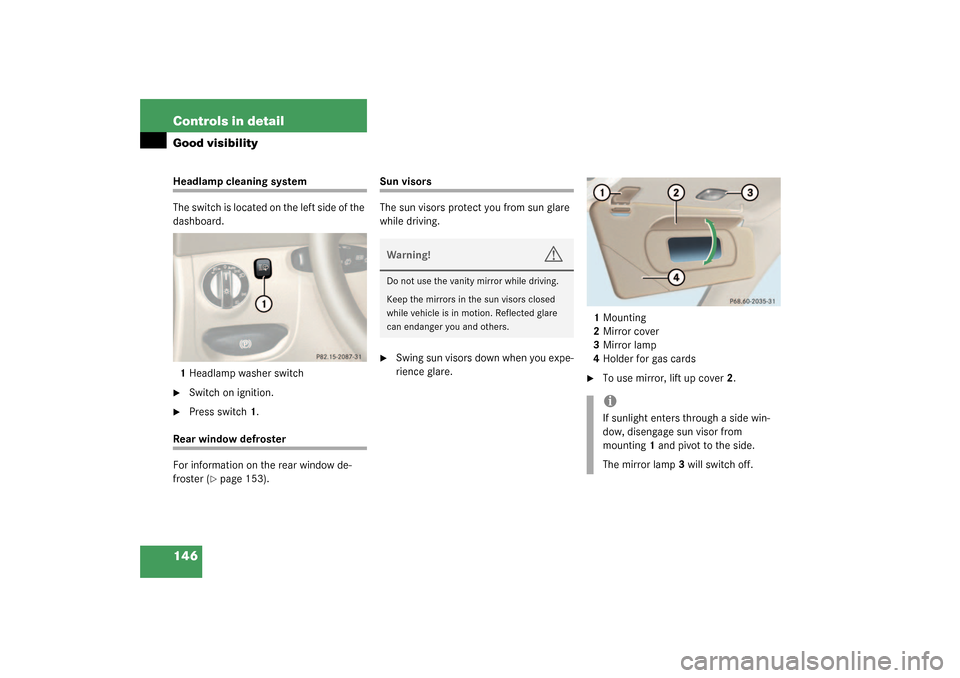
Sun visors
The sun visors protect you from sun glare
while driving.�
Swing sun visors down when you expe-
rience glare.1Mounting
2Mirror cover
3Mirror lamp
4Holder for gas cards
�
To use mirror, lift up cover2.
Warning!
G
Do not use the vanity mirror while driving.
Keep the mirrors in the sun visors closed
while vehicle is in motion. Reflected glare
can endanger you and others.
iIf sunlight enters through a side win-
dow, disengage sun visor from
mounting1 and pivot to the side.
The mirror lamp3 will switch off.