Page 108 of 416
108 Controls in detailSeats1Shoulder region support
2Side bolster adjustment
3Massage function (PULSE)
4Lumbar region support
Adjusting the multicontour seat in the or-
der listed above is recommended.�
Make sure that the ignition is switched
on.
All lamps in the instrument cluster light
up.Shoulder region support
�
Press
æ
or
ç
on switch1.
The air cushion inflates or deflates.
Lumbar region support
�
Press
k
or
j
on rocker
switch4.
This selects the air cushion you wish to
adjust.
�
Press
æ
or
ç
on rocker
switch4.
The air cushion inflates or deflates.Side bolsters adjustment
�
Adjust the side bolsters so that they
provide good lateral support using
switch 2.iWhen the engine is turned off, the last
cushion setting is retained in memory
and the cushion is automatically ad-
justed to this setting when the engine
is restarted.
Page 110 of 416
 or by the su")
110 Controls in detailSeatsSeat ventilation*
The switch is located on the door. Seat
ventilation can be activated manually with
the SmartKey in starter switch position1
or2 (
�page 31) or by the summer open-
ing feature (
�page 190).
The blue indicator lamps on the switch
show the ventilation level selected:
1Seat ventilation switch
�
Make sure the ignition is switched on.
All lamps in the instrument cluster light
up.
Switching on seat ventilation
�
Press switch1.
Three blue indicator lamps above the
switch light up.
Continue pressing switch until the de-
sired seat ventilation level is reached.Switching off seat ventilation
�
Press switch1 repeatedly until all indi-
cator lamps go out.
Level3
Three indicator lamps lit
2
Two indicator lamps lit
1
One indicator lamp lit
off
No indicator lamp lit
iThe seat ventilation is automatically set
to the highest level if activated via sum-
mer opening feature (
�page 190).
!If one or all of the lamps blink on the
seat ventilation switch, there is insuffi-
cient voltage since too many electrical
consumers are switched on. The seat
ventilation switches off automatically.
The seat ventilation will switch back on
again automatically as soon as suffi-
cient voltage is available.
Page 111 of 416
111 Controls in detailSeats
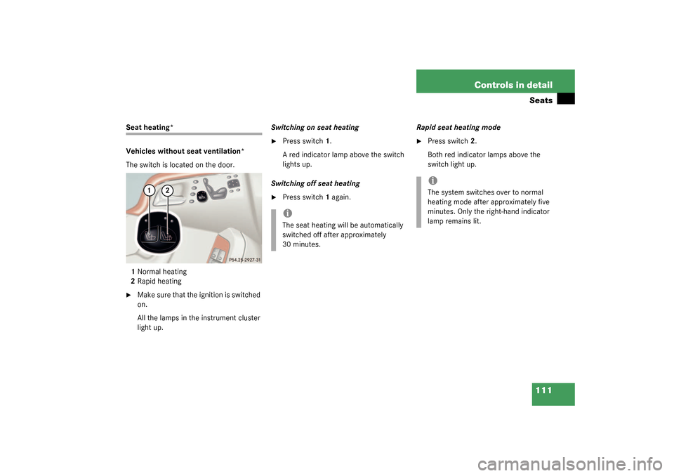
Seat heating*
Vehicles without seat ventilation*
The switch is located on the door.
1Normal heating
2Rapid heating�
Make sure that the ignition is switched
on.
All the lamps in the instrument cluster
light up.Switching on seat heating
�
Press switch1.
A red indicator lamp above the switch
lights up.
Switching off seat heating
�
Press switch1 again. Rapid seat heating mode
�
Press switch2.
Both red indicator lamps above the
switch light up.
iThe seat heating will be automatically
switched off after approximately
30 minutes.
iThe system switches over to normal
heating mode after approximately five
minutes. Only the right-hand indicator
lamp remains lit.
Page 112 of 416
112 Controls in detailSeatsSwitching off rapid seat heating mode�
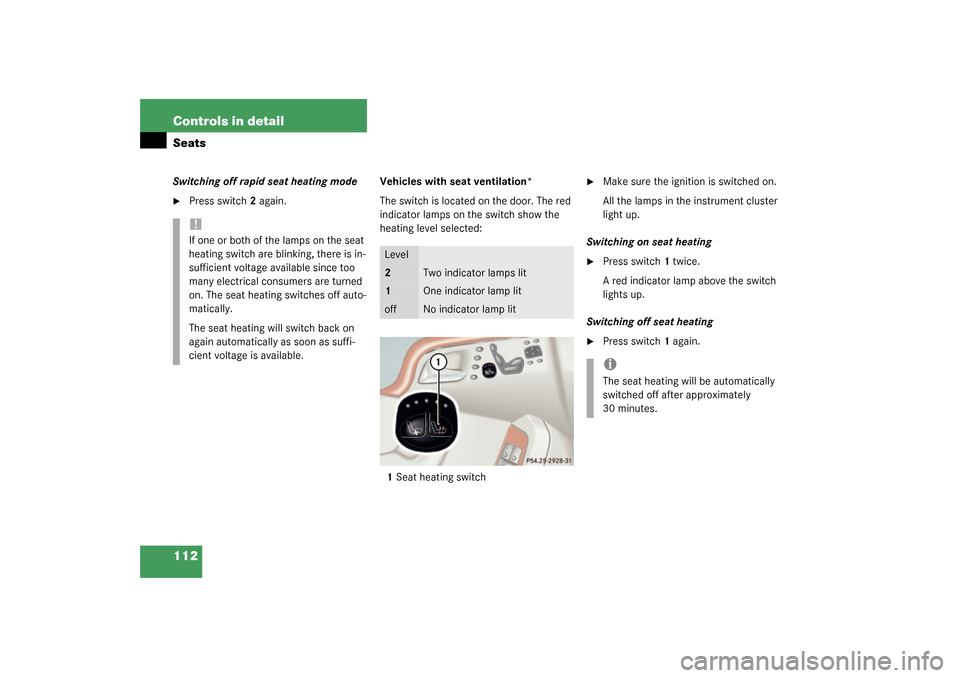
Press switch2 again. Vehicles with seat ventilation*
The switch is located on the door. The red
indicator lamps on the switch show the
heating level selected:
1Seat heating switch
�
Make sure the ignition is switched on.
All the lamps in the instrument cluster
light up.
Switching on seat heating
�
Press switch1 twice.
A red indicator lamp above the switch
lights up.
Switching off seat heating
�
Press switch1 again.
!If one or both of the lamps on the seat
heating switch are blinking, there is in-
sufficient voltage available since too
many electrical consumers are turned
on. The seat heating switches off auto-
matically.
The seat heating will switch back on
again automatically as soon as suffi-
cient voltage is available.
Level2
Two indicator lamps lit
1
One indicator lamp lit
off
No indicator lamp lit
iThe seat heating will be automatically
switched off after approximately
30 minutes.
Page 123 of 416
123 Controls in detail
Lighting
Switching on rear fog lamp�
Make sure that the low beam head-
lamps are switched on.
�
Pull out exterior lamp switch to second
stop.
The yellow indicator lamp
†
in the
lamp switch lights up.
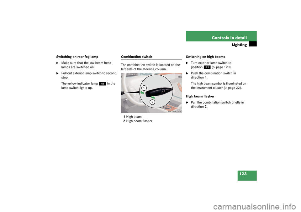
Combination switch
The combination switch is located on the
left side of the steering column.
1High beam
2High beam flasherSwitching on high beams
�
Turn exterior lamp switch to
position
B
(�page 120).
�
Push the combination switch in
direction1.
The high beam symbol is illuminated on
the instrument cluster (
�page 22).
High beam flasher
�
Pull the combination switch briefly in
direction2.
Page 127 of 416
.
The instrume")
127 Controls in detail
Instrument cluster
Instrument cluster
A full view illustration of the instrument
cluster can be found in the “At a glance”
section of this manual (
�page 22).
The instrument cluster is activated when
you
�
open a door
�
turn on the ignition
�
press the reset button
J
(�page 22)
�
switch on the exterior lamps
You can change the instrument cluster set-
tings in the Instrument cluster submenu of
the control system (
�page 149).
Instrument cluster illumination
1Knob for adjusting instrument cluster
illumination
Use knob1 to adjust the illumination
brightness for the instrument cluster.
�
Press knob1. The knob will pop out.
To brighten illumination
�
Turn knob1 in the instrument cluster
clockwise.
The instrument cluster illumination will
brighten.
To dim illumination
�
Turn knob1 in the instrument cluster
counterclockwise.
The instrument cluster illumination will
dim.
iThe instrument cluster illumination is
dimmed or brightened automatically to
suit ambient light conditions.
The instrument cluster illumination will
also be adjusted automatically when
you switch on the vehicle’s exterior
lamps.
Page 128 of 416
,
i.e. c")
128 Controls in detailInstrument clusterCoolant temperature gaugeDuring severe operating conditions and
stop-and-go city traffic, the coolant tem-
perature may rise close to 248° F (120°C),
i.e. close to the red zone of the tempera-
ture gauge.
The engine should not be operated with
the coolant temperature above 248° F
(120°C), i.e. in the red zone of the temper-
ature gauge. Doing so may cause serious
engine damage which is not covered by the
Mercedes-Benz Limited Warranty.
Trip odometer
Make sure you are viewing the trip odome-
ter display.�
Press the
è
or
ÿ
button on the
multifunction steering wheel repeated-
ly until the trip odometer appears if it is
not displayed (
�page 130).
�
Press and hold reset button
J
on the
instrument cluster (
�page 22) until
the trip odometer is reset.
Warning!
G
�
Driving when your engine is badly over-
heated can cause some fluids which
may have leaked into the engine com-
partment to catch fire. You could be se-
riously burned.
�
Steam from an overheated engine can
cause serious burns and can occur just
by opening the engine hood. Stay away
from the engine if you see or hear steam
coming from it.
Turn off the engine, get out of the vehicle
and do not stand near the vehicle until it
cools down.
iExcessive coolant temperatures trigger
a warning in the multifunction display.
Page 129 of 416

129 Controls in detail
Instrument cluster
Tachometer
The red marking on the tachometer de-
notes excessive engine speed.
To help protect the engine, the fuel supply
is interrupted if the engine is operated
within the red marking.
S 55 AMG
The tachometer of the S 55 AMG does not
have a red marking denoting excessive en-
gine speed.
To help protect the engine, the fuel supply
is interrupted if the engine is operated at
an excessive engine speed.
Outside temperature indicator
The temperature sensor is located in the
front bumper area. Due to its location, the
sensor can be affected by road or engine
heat during idling or slow driving. There-
fore, the accuracy of the displayed temper-
a t u r e c a n o n l y b e v e r i f i e d b y c o m p a r i s o n t o
a thermometer placed next to the sensor,
not by comparison to external displays
(e.g. bank signs etc.).When moving the vehicle into colder ambi-
ent temperatures (e.g. when leaving your
garage), you will notice a delay before the
lower temperature is displayed.
A delay also occurs when ambient temper-
atures rise. This prevents inaccurate tem-
perature indications caused by heat
radiated from the engine during idling or
slow driving.
!Avoid driving at excessive engine
speeds, as it may result in serious en-
gine damage that is not covered by the
Mercedes-Benz Limited Warranty.
Warning!
G
The outside temperature indicator is not de-
s i g n e d t o s e r v e a s a n i c e - w a r n i n g d e v i c e a n d
is therefore unsuitable for that purpose.
Indicated temperatures just above the freez-
ing point do not guarantee that the road sur-
face is free of ice. The road may still be icy,
especially in wooded areas or on bridges.

4Lumbar region support
Adjusting the multicontour seat in the or-
der listed above is recommended")