Page 135 of 321

135 Controls in detail
Power windows
Opening the windows�
Press switch
k
to resistance point.
The window will move downwards until
you release the switch.
Closing the windows
�
Press switch
j
to resistance point.
The window will move upwards until
you release the switch.
Fully opening the windows
�
Press switch
k
past the point of re-
sistance and release.Fully closing the windows
�
Press switch
j
past the point of re-
sistance and release.
Stopping the windows
�
Briefly press switch
k
or
j
.
!If the side window is blocked in the up-
per area, the closing process is inter-
rupted and the window reopens
slightly.
Remove the obstruction, press switch j
past the point of resistance again
and release.
If the window still does not close
without an object having been trapped,
then hold the
j
switch down. The
side window will then close without the
obstruction sensor function.
iIf the driver’s window cannot be auto-
matically closed without an object
having been trapped, press the
j
switch past the point of resistance
again within five seconds and release.
The side windows will now close with-
out the obstruction sensor function.
Warning!
G
When closing the windows, make sure that
there is no danger of anyone being harmed
by the closing procedure.
Page 140 of 321
140 Controls in detailLoadingCargo tie-down rings
The cargo area is provided with four
tie-down rings. Additional two rings are lo-
cated at the rear of front seats.Cargo tie-down ring
Carefully secure cargo by applying even
load on all rings with rope of sufficient
strength to hold down the cargo.Hooks
Four hooks located on the rear compart-
ment trim panels, two on each side.
HooksUse the hooks to secure light weight items.
The maximum permissible weight per hook
is 9lbs.(4kg).
iThe trunk is the preferred place to carry
objects. The enlarged cargo area
should only be used for items which do
not fit in the trunk alone.
iWhile the partition net (
�page 141)
will help protect you from smaller ob-
jects, it cannot prevent the movement
of large, heavier objects into the pas-
senger area in an accident. Such items
must be properly secured using the
cargo tie-down rings in the cargo area
floor.
Page 145 of 321
145 Controls in detail
Loading
Roof rack*Roof rails
For further information inquire at your
Mercedes-Benz Light Truck Center.
Warning!
G
Take into consideration that when the roof
rack is loaded, the handling characteristics
are different from those when operating the
vehicles without the roof rack loaded.
The maximum roof load when using roof
rack systems is 220 lbs. (100 kg).
!Attach roof racks to the roof rails only.
Use only those roof racks approved by
Mercedes-Benz for your vehicle model.
Follow manufacturer’s installation in-
structions.
The vehicle could otherwise be dam-
aged.
Page 150 of 321

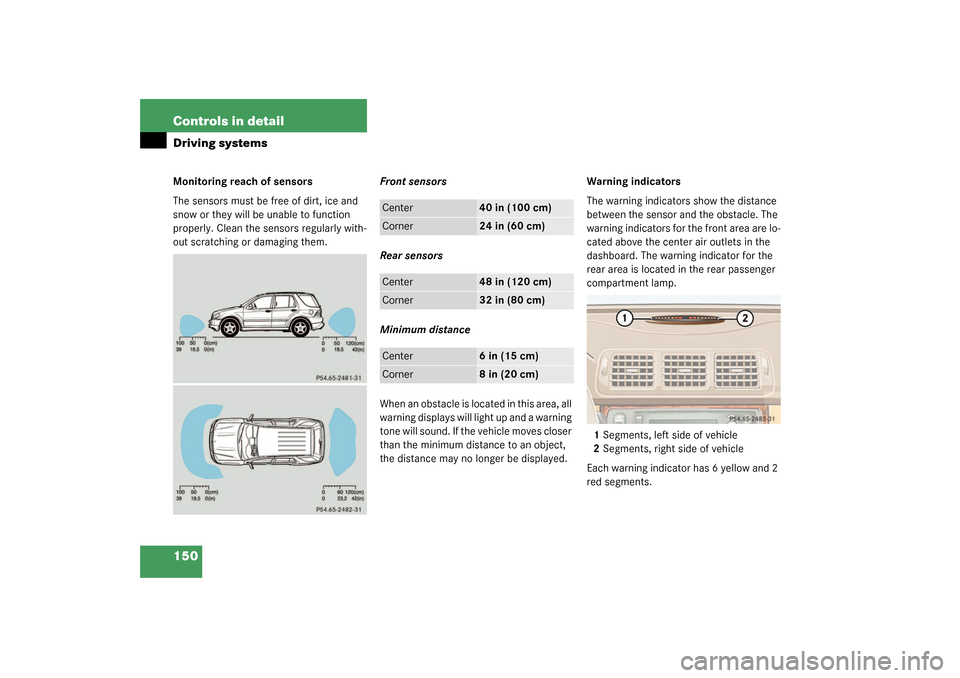
150 Controls in detailDriving systemsMonitoring reach of sensors
The sensors must be free of dirt, ice and
snow or they will be unable to function
properly. Clean the sensors regularly with-
out scratching or damaging them.Front sensors
Rear sensors
Minimum distance
When an obstacle is located in this area, all
warning displays will light up and a warning
tone will sound. If the vehicle moves closer
than the minimum distance to an object,
the distance may no longer be displayed.Warning indicators
The warning indicators show the distance
between the sensor and the obstacle. The
warning indicators for the front area are lo-
cated above the center air outlets in the
dashboard. The warning indicator for the
rear area is located in the rear passenger
compartment lamp.
1Segments, left side of vehicle
2Segments, right side of vehicle
Each warning indicator has 6 yellow and 2
red segments.
Center
40 in (100 cm)
Corner
24 in (60 cm)
Center
48 in (120 cm)
Corner
32 in (80 cm)
Center
6 in (15 cm)
Corner
8 in (20 cm)
Page 151 of 321

151 Controls in detail
Driving systems
The selector lever position determines
which warning indicator is activated.
As soon as the sensors detect an obstacle,
one or more segments light up, depending
on the distance. An intermittent acoustic
warning will also sound as the seventh seg-
ment lights up and a constant acoustic
warning lasting a maximum of 3 seconds
will sound for the eighth segment.Switching Parktronic on/off
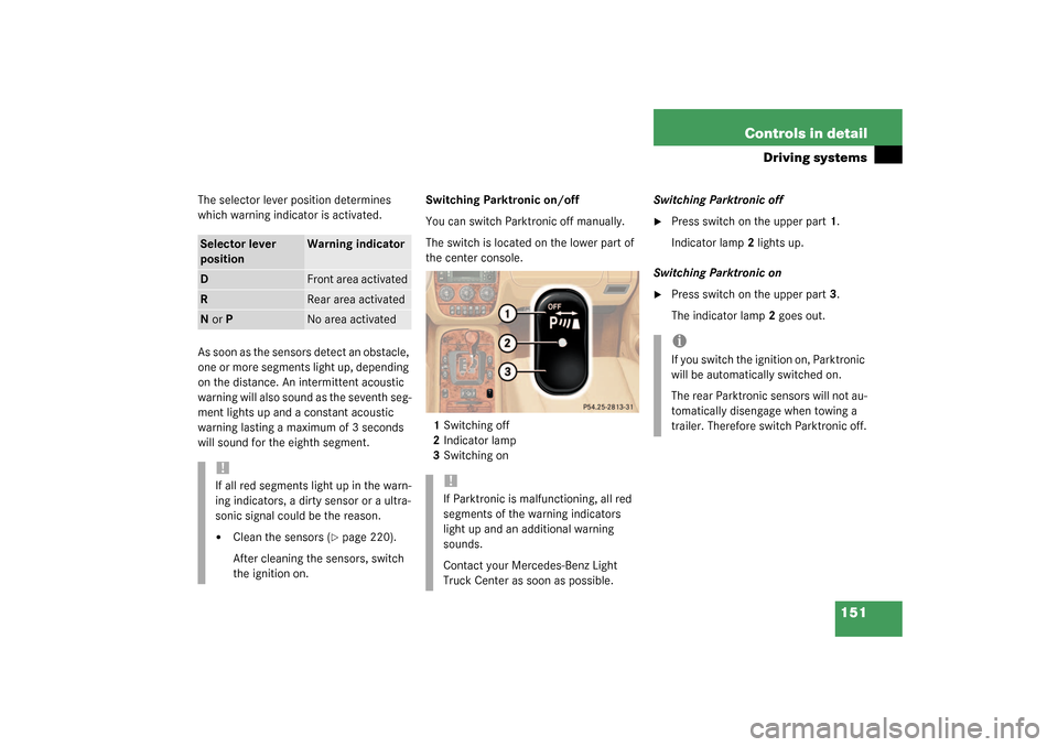
You can switch Parktronic off manually.
The switch is located on the lower part of
the center console.
1Switching off
2Indicator lamp
3Switching onSwitching Parktronic off
�
Press switch on the upper part1.
Indicator lamp2 lights up.
Switching Parktronic on
�
Press switch on the upper part3.
The indicator lamp2 goes out.
Selector lever
position
Warning indicator
D
Front area activated
R
Rear area activated
N or P
No area activated
!If all red segments light up in the warn-
ing indicators, a dirty sensor or a ultra-
sonic signal could be the reason.�
Clean the sensors (
�page 220).
After cleaning the sensors, switch
the ignition on.
!If Parktronic is malfunctioning, all red
segments of the warning indicators
light up and an additional warning
sounds.
Contact your Mercedes-Benz Light
Truck Center as soon as possible.
iIf you switch the ignition on, Parktronic
will be automatically switched on.
The rear Parktronic sensors will not au-
tomatically disengage when towing a
trailer. Therefore switch Parktronic off.
Page 156 of 321

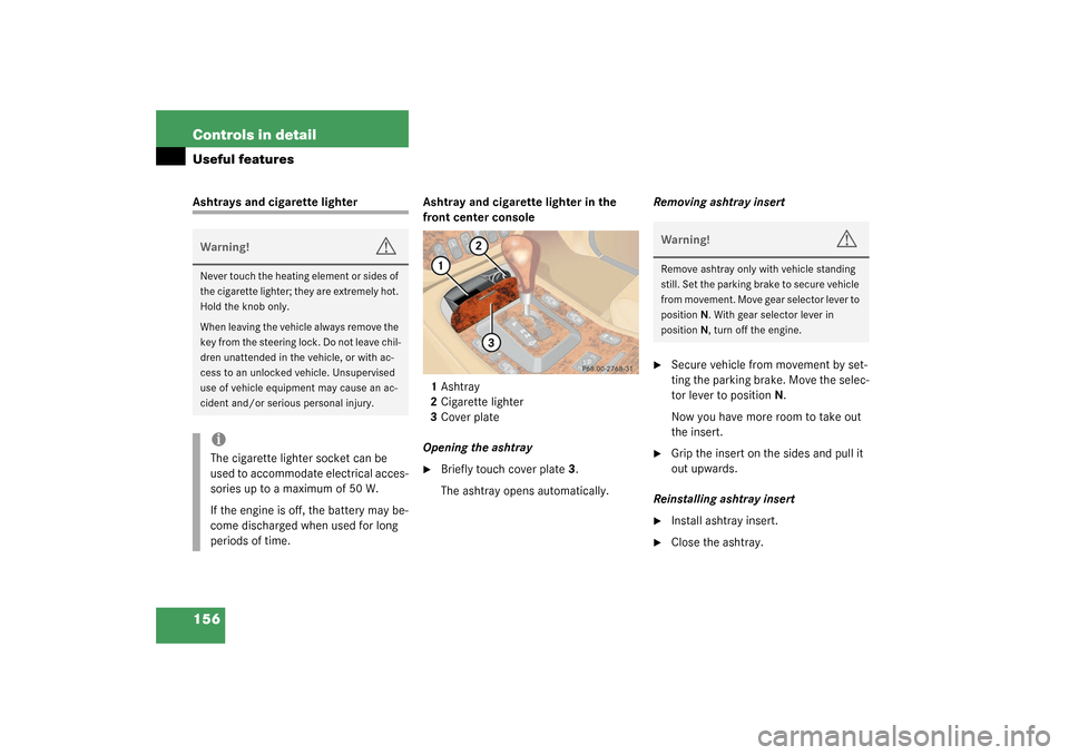
156 Controls in detailUseful featuresAshtrays and cigarette lighter Ashtray and cigarette lighter in the
front center console
1Ashtray
2Cigarette lighter
3Cover plate
Opening the ashtray
�
Briefly touch cover plate3.
The ashtray opens automatically.Removing ashtray insert
�
Secure vehicle from movement by set-
ting the parking brake. Move the selec-
tor lever to positionN.
Now you have more room to take out
the insert.
�
Grip the insert on the sides and pull it
out upwards.
Reinstalling ashtray insert
�
Install ashtray insert.
�
Close the ashtray.
Warning!
G
Never touch the heating element or sides of
the cigarette lighter; they are extremely hot.
Hold the knob only.
When leaving the vehicle always remove the
key from the steering lock. Do not leave chil-
dren unattended in the vehicle, or with ac-
cess to an unlocked vehicle. Unsupervised
use of vehicle equipment may cause an ac-
cident and/or serious personal injury.iThe cigarette lighter socket can be
used to accommodate electrical acces-
sories up to a maximum of 50 W.
If the engine is off, the battery may be-
come discharged when used for long
periods of time.
Warning!
G
Remove ashtray only with vehicle standing
still. Set the parking brake to secure vehicle
from movement. Move gear selector lever to
positionN. With gear selector lever in
positionN, turn off the engine.
Page 157 of 321
157 Controls in detail
Useful features
Cigarette lighter�
Switch on the ignition.
�
Push in cigarette lighter2
(�page 156).
The cigarette lighter will pop out auto-
matically when hot.
Ashtray and cigarette lighter in the rear
center console
1Ashtray
2Cigarette lighter
3Cover plate
Opening the ashtray
�
Briefly touch cover plate3.
The ashtray opens automatically.
Removing ashtray insert
�
Grip the insert on the sides and pull it
out upwards.Reinstalling ashtray insert
�
Install ashtray insert.
�
Close the ashtray.
Cigarette lighter
�
Switch on the ignition.
�
Push in cigarette lighter2.
The cigarette lighter will pop out auto-
matically when hot.
!Close the ashtray in the rear center
console before folding the rear seat
bench.
Page 158 of 321

158 Controls in detailUseful featuresElectrical outletElectrical outletOne outlet is located in the front passen-
ger footwell and another on the right-hand
side of the luggage compartment.�
Flip up cover and insert electrical plug
(cigarette lighter type).
Telephone*
Radio transmitters, such as a portable tele-
phone or a citizens band unit, should only
be used inside the vehicle if they are con-
nected to an antenna that is installed on
the outside of the vehicle.
The external antenna must be approved by
Mercedes-Benz. Please contact an autho-
rized Mercedes-Benz Light Truck Center
for information on the installation of an ap-
proved external antenna. Refer to the radio
transmitter operation instructions regard-
ing use of an external antenna.
iThe outlets function even if the key is
not in the ignition.
The electrical outlet can be used to ac-
commodate electrical consumers (e.g.
air pump, auxiliary lamps) up to a max-
imum of 180 W.
If the engine is off, the battery may be-
come discharged if used for long peri-
ods of time.
Warning!
G
Never operate radio transmitters equipped
with a built-in or attached antenna (i.e. with-
out being connected to an external antenna)
from inside the vehicle while the engine is
running. Doing so could lead to a malfunc-
tion of the vehicle’s electronic system, pos-
sibly resulting in an accident and/or serious
personal injury.