Page 160 of 360

160 Controls in detailSliding/pop-up roof
Sliding/pop-up roofOpening and closing the sliding/pop-up roof
1Push back to slide roof open
2Push forward to slide roof closed
3Push up to raise roof at rear
4Pull down to lower roof at rear
�
Turn the key in the starter switch to
position1 or2.
Opening and closing the sliding/pop-up
roof
�
To open, close, raise or lower the slid-
ing/pop-up roof, move the switch to re-
sistance point in the required direction.
Release the switch when the roof has
reached the required position.Opening and closing the sliding/pop-up
roof automatically
�
Move the switch past resistance point
in the direction required and release.
The sliding/pop-up roof opens or clos-
es completely.
Stopping the sliding/pop-up roof
�
Move the switch in any direction.
If the movement of the sliding/pop-up
roof is blocked during the closing pro-
cedure, the roof will stop and reopen
slightly.
Warning!
G
When closing the sliding/pop-up roof, make
s ur e th at th er e is n o da ng er o f a ny o n e bei ng
harmed by the closing procedure.
The closing procedure of the sliding/pop-up
roof can be immediately reversed by either
moving the switch in any direction,
or pressing button
Œ
on the SmartKey
and holding it.
When leaving the vehicle, always remove the
key from starter switch, and lock your vehi-
cle. Do not leave children unattended in the
vehicle, or with access to an unlocked vehi-
cle. Unsupervised use of vehicle equipment
can cause an accident and/or serious per-
sonal injury.
!To avoid damaging the seals, do not
transport any objects with sharp edges
which can stick out of the slid-
ing/pop-up roof.
The sliding/pop-up roof can be opened
or closed manually should an electrical
malfunction occur (
�page 276).
Page 166 of 360

166 Controls in detailDriving systemsRange of the sensors
To function properly, the sensors must be
free of dirt, ice, snow and slush. Clean the
sensors regularly, being careful not to
scratch or damage them.Minimum distance
The minimum distance between the sen-
sors and an obstacle is approximately
20 in (50 cm). If you encounter an obstacle
in this range, all the warning lamps light up
and you hear a warning signal. If the obsta-
cle is closer than the minimum distance,
the actual distance may no longer be indi-
cated by the system.
Center
approx. 59.1 in (150 cm)
Corners
approx. 40 in (100 cm)
!During parking maneuvers, pay special
attention to objects located above or
below the height of the sensors (e.g.
planters or trailer hitches). The Rear
Park Assist system will not detect such
objects at close range and damage to
your vehicle or the object may result.
Ultrasonic signals from outside sourc-
es (e.g. truck air brakes or jackham-
mers) may impair the operation of the
Rear Park Assist system.
Page 167 of 360

167 Controls in detail
Driving systems
Warning indicator
Visual signals indicate to the driver the rel-
ative distance between the sensors and an
obstacle. The warning indicator is located
next to the tailgate.Warning indicatorAs your vehicle approaches an object, one
or more segments will light up, depending
on the distance. When the sixth segment
lights, you have reached the minimum dis-
tance.An intermittent acoustic warning will
sound as the fourth segment lights up and
a constant acoustic warning lasting a max-
imum of three seconds will sound for the
sixth segment.
Rear Park Assist malfunction
There is a malfunction in the Rear Park As-
sist system if:
�
a low warning tone sounds while the
vehicle is reversing
The Rear Park Assist sensors are dirty
or malfunctioning.�
Clean the Rear Park Assist system
sensors (
�page 234).
�
Switch on the ignition again.
�
no segments light up and no warning
sounds
The Rear Park Assist is malfunctioning.�
Have the Rear Park Assist system
checked by an authorized
Mercedes-Benz Light Truck Center
as soon as possible.
Malfunction may also be caused by inter-
ference from other radio or ultrasonic sig-
nals.
�
Check the Rear Park Assist operation
at another location to rule out interfer-
ence from outside radio or ultrasonic
signals.
Page 172 of 360
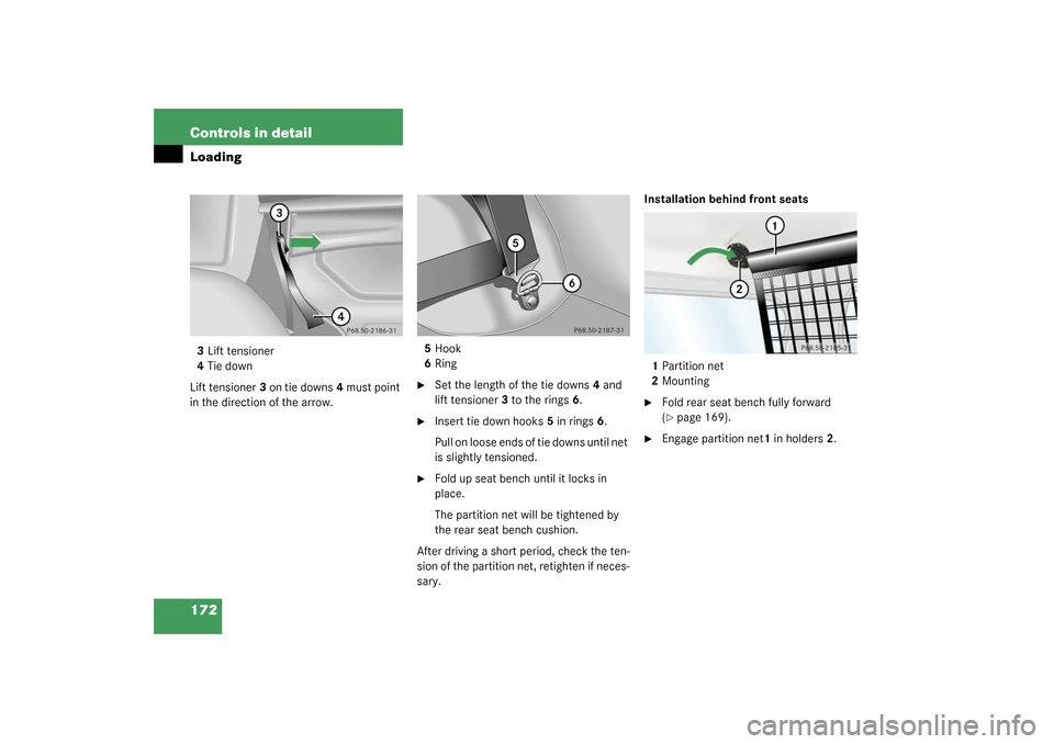
172 Controls in detailLoading3Lift tensioner
4Tie down
Lift tensioner3 on tie downs4 must point
in the direction of the arrow.5Hook
6Ring
�
Set the length of the tie downs4 and
lift tensioner3 to the rings6.
�
Insert tie down hooks5 in rings6.
Pull on loose ends of tie downs until net
is slightly tensioned.
�
Fold up seat bench until it locks in
place.
The partition net will be tightened by
the rear seat bench cushion.
After driving a short period, check the ten-
sion of the partition net, retighten if neces-
sary.Installation behind front seats
1Partition net
2Mounting
�
Fold rear seat bench fully forward
(�page 169).
�
Engage partition net1 in holders2.
Page 179 of 360
179 Controls in detail
Useful features
Cup holder in rear passenger footwellParcel net in front passenger footwell
A small convenience parcel net is located
in the front passenger footwell. It is for
small and light items, such as road maps,
mail, etc.
Ashtrays
Center console ashtray
1Ashtray
2Cigarette lighter
3Cover plate
Opening ashtray�
Briefly push the cover plate3.
The ashtray opens automatically.
!Before folding the seat backrest for-
ward and the rear seat bench down, be
sure that all containers in the rear cup
holder are removed.
Warning!
G
Do not place heavy or fragile objects, or ob-
jects having sharp edges in the parcel net.
In an accident, during hard braking or sud-
den maneuvers, they could be thrown
around inside the vehicle and cause injury to
vehicle occupants.!When large objects are stored in the
parcel net, do not slide the seat fully
forward, it could damage them.
Page 181 of 360
181 Controls in detail
Useful features
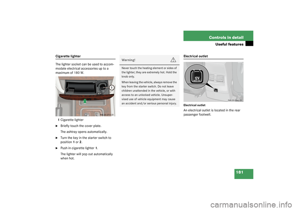
Cigarette lighter
The lighter socket can be used to accom-
modate electrical accessories up to a
maximum of 180 W.
1Cigarette lighter�
Briefly touch the cover plate.
The ashtray opens automatically.
�
Turn the key in the starter switch to
position1 or2.
�
Push in cigarette lighter1.
The lighter will pop out automatically
when hot.
Electrical outletElectrical outletAn electrical outlet is located in the rear
passenger footwell.
Warning!
G
Never touch the heating element or sides of
the lighter; they are extremely hot. Hold the
knob only.
When leaving the vehicle, always remove the
key from the starter switch. Do not leave
children unattended in the vehicle, or with
access to an unlocked vehicle. Unsuper-
vised use of vehicle equipment may cause
an accident and/or serious personal injury.
N
Page 182 of 360
.
Telephone*
Radio transmitters, such")
182 Controls in detailUseful features�
Turn the key in the starter switch to
position1 or 2.
�
Flip up cover and insert electrical plug
(cigarette lighter type).
Telephone*
Radio transmitters, such as a portable tele-
phone or a citizens band unit, should only
be used inside the vehicle if they are con-
nected to an antenna that is installed on
the outside of the vehicle.
T h e e x t e r n a l a n t e n n a m u s t b e a p p r o ve d b y
Mercedes-Benz. Please contact an autho-
rized Mercedes-Benz Light Truck Center
for information on the installation of an ap-
proved external antenna. Refer to the radio
transmitter operation instructions regard-
ing use of an external antenna.
iThe electrical outlet can be used to ac-
commodate electrical consumers (e.g.
air pump, auxiliary lamps) up to a max-
imum of 180 W.
Warning!
G
Never operate radio transmitters equipped
with a built-in or attached antenna (i.e. with-
out being connected to an external antenna)
from inside the vehicle while the engine is
running. Doing so could lead to a malfunc-
tion of the vehicle’s electronic system, pos-
sibly resulting in an accident and/or
personal injury.
Warning!
G
Please do not forget that your primary re-
sponsibility is to drive the vehicle. A driver’s
attention to the road must always be
his /her primary focus when driving. For
your safety and the safety of others, we rec-
o m m e n d t h a t y o u p u l l o v e r t o a s a f e l o c a t i o n
and stop before placing or taking a tele-
phone call.
If you choose to use the telephone
1 while
driving, please use the hands-free device
and only use the telephone when road, traf-
fic and weather conditions permit. Some ju-
risdictions prohibit the driver from using a
cellular telephone while driving a vehicle.
Only operate the COMAND (Cockpit Man-
agement and Data System)
1 if road, traffic
and weather conditions permit.
Bear in mind that at a speed of just 30 mph
(approximately 50 km / h), your vehicle is
covering a distance of approx. 44 feet (ap-
proximately 13.5 m) every second.
1Observe all legal requirements
Page 184 of 360

184 Controls in detailUseful featuresShortly after the completion of your ac-
quaintance call, you will receive a user ID
and password via first call mail. By visiting
www.mbusa.com and selecting “Tele Aid”
(USA only), you will have access to account
information, remote door unlock, profile
and more.System self-check
Initially, after turning the key in starter
switch to position2, malfunctions are de-
tected and indicated (the indicator lamps
in the SOS button, the Roadside Assis-
tance button
•
and the Information
button
¡
stay on longer than
10 seconds or do not come on). The mes-
sage
TELE AID – VISIT WORKSHOP!
ap-
pears for approx. 10 seconds in the
multifunction display.
iThe SOS button is located above the in-
side rear view mirror.
The Roadside Assistance button
•
and the Information button
¡
are
located below the center armrest cov-
er.
!The Tele Aid system utilizes the cellular
network for communication and the
GPS (Global Positioning System) satel-
lites for vehicle location. If either of
these signals are unavailable, the
Tele Aid system may not function and if
this occurs, assistance must be sum-
moned by other means.
Warning!
G
If the indicator lamps in the SOS button, in
the Roadside Assistance button and/or in
the Information button do not come on dur-
ing the system self-check or if any of these
indicators remain illuminated constantly in
red and/or the message
TELE AID - VIS-
IT WORKSHOP
is displayed in the multifunc-
tion display after the system self-check, a
malfunction in the system has been detect-
ed.
If a malfunction is indicated as outlined
above, the system may not operate as ex-
pected. Have the system checked at the
nearest Mercedes-Benz Light Truck Center
as soon as possible.