Page 94 of 360

94 Controls in detailSeatsMulticontour seat*
Some models may be equipped with driv-
er’s multicontour seat. This seat has a
movable seat cushion and inflatable air
cushions built into the seat backrest to
provide additional lumbar and side sup-
port.
The seat cushion movement and amount of
seat backrest cushion height and curva-
ture can be continuously varied with regu-
lators on the right side of the seat after
turning the SmartKey in the starter switch
to position2.1Seat cushion length
2Seat backrest contour in the lumbar
area
3Seat backrest contour in upper back
area
4Seat backrest side bolsters
�
Check that the ignition is switched on.
All the lamps in the instrument cluster
should light up.
Seat cushion length
�
Adjust the seat cushion to the length of
your upper leg using switch 1.Backrest contour in the lumbar area
�
Adjust the contour of the backrest in
the lumbar area to the desired position
using switch 2.
Backrest contour in the upper back
area
�
Adjust the contour of the backrest in
the upper back area to the desired po-
sition using switch 3.
Backrest side bolsters
�
Adjust the backrest side bolsters so
that they provide good lateral support
using switch 4.
Page 95 of 360

95 Controls in detail
Seats
Heated seats
Driver’s and front passenger seats
The switch is located in the center console.
1Normal heating
2Rapid heating�
Check that the ignition is switched on.
All the lamps in the instrument cluster
light up.Switching on seat heating
�
Press upper switch position1.
A red indicator lamp on the switch
lights up.
Switching on rapid seat heating
�
Press lower switch position2.
Both red indicator lamps on the switch
light up.Switching off seat heating
�
If one indicator lamp is on, press upper
switch position1.
�
If both indicator lamps are on, press
lower switch position2.
!If one or both of the lamps on the seat
heater switch are blinking, there is in-
sufficient voltage available as too many
electrical consumers are turned on.
The seat heater switches off automati-
cally.
The seat heater will switch back on
again automatically as soon as suffi-
cient voltage is available.
iThe system switches over to normal
heating mode after approximately five
minutes. Only one indicator lamp re-
mains lit. iThe seat heater will be automatically
switched off after approximately
30 minutes.
Page 96 of 360
 pil-
lar.
1Normal heating
2Rapid heating�
Check that the ignition is switched on.
All the lamps in the instrument cluster")
96 Controls in detailSeatsRear seats
The switch is located on the B (center) pil-
lar.
1Normal heating
2Rapid heating�
Check that the ignition is switched on.
All the lamps in the instrument cluster
light up.Switching on seat heating
�
Press upper switch position1.
A red indicator lamp on the switch
lights up.
Switching on rapid seat heating
�
Press lower switch position2.
Both red indicator lamps on the switch
light up.Switching off seat heating
�
If one indicator lamp is on, press upper
switch position1.
�
If both indicator lamps are on, press
lower switch position2.
!If one or both of the lamps on the seat
heater switch are blinking, there is in-
sufficient voltage available since too
many electrical consumers are turned
on. The seat heater switches off auto-
matically.
The seat heater will switch back on
again automatically as soon as suffi-
cient voltage is available.
iThe system switches over to normal
heating mode after approximately five
minutes. Only one indicator lamp re-
mains lit. iThe seat heater will be automatically
switched off after approximately
30 minutes.
Page 103 of 360
103 Controls in detail
Lighting
Switching on rear fog lamp�
Check that the low beam headlamps
are switched on.
�
Pull out exterior lamp switch to second
stop.
The yellow indicator lamp
†
in the
lamp switch lights up.
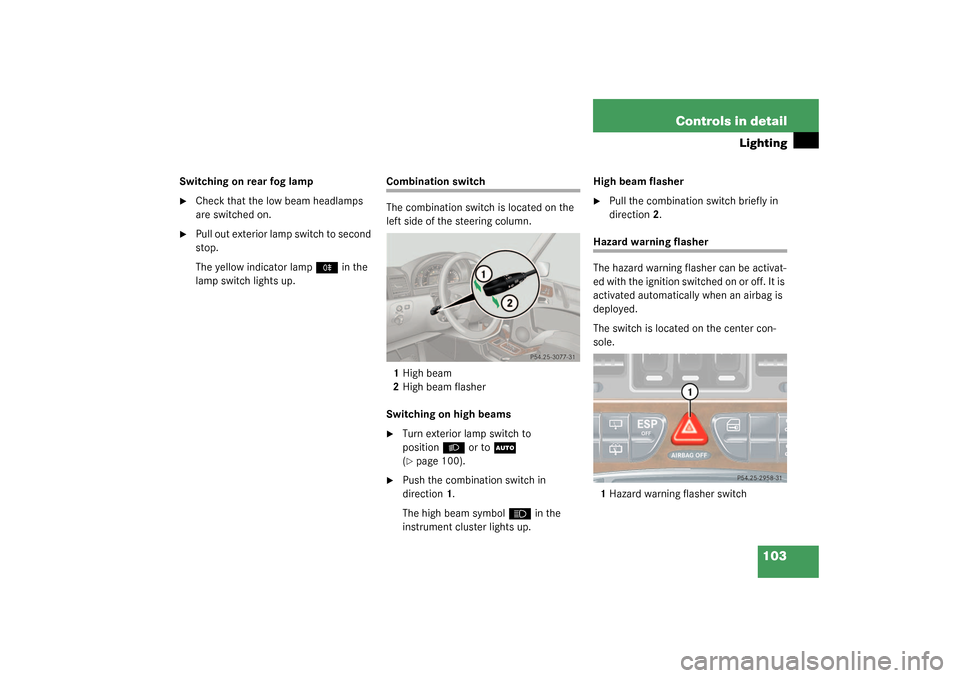
Combination switch
The combination switch is located on the
left side of the steering column.
1High beam
2High beam flasher
Switching on high beams�
Turn exterior lamp switch to
position
B
or to
U
(
�page 100).
�
Push the combination switch in
direction1.
The high beam symbol
A
in the
instrument cluster lights up.High beam flasher
�
Pull the combination switch briefly in
direction2.
Hazard warning flasher
The hazard warning flasher can be activat-
ed with the ignition switched on or off. It is
activated automatically when an airbag is
deployed.
The switch is located on the center con-
sole.
1Hazard warning flasher switch
Page 108 of 360
.
1Reset knob
Th")
108 Controls in detailInstrument cluster
Instrument clusterA full view illustration of the instrument
cluster can be found in the “At a glance”
section of this manual (
�page 24).
1Reset knob
The instrument cluster is activated when
you:
�
open a door
�
turn on the ignition
�
press reset knob1
�
switch on the exterior lamps
You can change the instrument cluster set-
tings in the Instrument cluster submenu of
the control system (
�page 122).
Instrument cluster illumination
Use the reset knob to adjust the illumina-
tion brightness for the instrument cluster.
To brighten illumination�
Turn reset knob1 in the instrument
cluster clockwise.
The instrument cluster illumination will
brighten.To dim illumination
�
Turn reset knob1 in the instrument
cluster counterclockwise.
The instrument cluster illumination will
dim.
Coolant temperature display
iThe instrument cluster illumination is
dimmed or brightened automatically to
suit ambient light conditions.
The instrument cluster illumination will
also be adjusted automatically when
you switch on the vehicle’s exterior
lamps.
Warning!
G
�
Driving when your engine is badly over-
heated can cause some fluids which
may have leaked into the engine com-
partment to catch fire. You could be se-
riously burned
�
Steam from an overheated engine can
cause serious burns and can occur just
by opening the engine hood. Stay away
f r o m t h e e n g i n e i f y o u s e e o r h e a r s t e a m
coming from it.
Turn off the engine, get out of the vehicle
and do not stand near the vehicle until it
cools down.
Page 109 of 360

109 Controls in detail
Instrument cluster
�
Turn the SmartKey in the starter switch
to position1 or2.
�
Call up the trip odometer and main
odometer by pressing button
è
or
ÿ
on the multifunction steering
wheel (�page 112).
�
Press button
j
or
k
until the
coolant temperature display appears.During severe operating conditions and
stop-and-go city traffic, the coolant tem-
perature may rise close to 248°F (120°C).
The engine should not be operated with
the coolant temperature above 248°F
(120°C). Doing so may cause serious en-
gine damage which is not covered by the
Mercedes-Benz Limited Warranty.
Trip odometer�
Make sure you are viewing the trip
odometer and main odometer
(�page 111) in the multifunction dis-
play.
�
Press and hold the reset knob on the in-
strument cluster (
�page 108) until the
trip odometer is reset.
Tachometer
The red marking on the tachometer de-
notes excessive engine speed.
To help protect the engine, the fuel supply
is interrupted if the engine is operated
within the red marking.
iExcessive coolant temperatures trigger
a warning in the multifunction display
(�page 252).
!Avoid driving at excessive engine
speeds, as it may result in serious en-
gine damage that is not covered by the
Mercedes-Benz Limited Warranty.
Page 110 of 360

110 Controls in detailInstrument clusterOutside temperature indicatorThe temperature sensor is located in the
front bumper area. Due to its location, the
sensor can be affected by road or engine
heat during idling or slow driving. This
means that the accuracy of the displayed
temperature can only be verified by com-
parison to a thermometer placed next to
the sensor, not by comparison to external
displays (e.g. bank signs, etc.).When moving the vehicle into colder ambi-
ent temperatures (e.g. when leaving your
garage), you will notice a delay before the
lower temperature is displayed.
A delay also occurs when ambient temper-
atures rise. This prevents inaccurate tem-
perature indications caused by heat
radiated from the engine during idling or
slow driving.Warning!
G
The outside temperature indicator is not de-
signed to serve as an ice-warning device and
is therefore unsuitable for that purpose.
Indicated temperatures just above the freez-
ing point do not guarantee that the road sur-
face is free of ice. The road may still be icy,
especially in wooded areas or on bridges.
Page 111 of 360

111 Controls in detail
Control system
Control system
The control system is activated as soon as
the key in the starter switch is turned to
position1. The control system enables you
to�
call up information about your vehicle
�
change vehicle settings
For example, you can use the control sys-
tem to find out when your vehicle is next
due for service, to set the language for
messages in the instrument cluster display
and much more.
The control system relays information to
the multifunction display.
Multifunction display
1Trip odometer
2Main odometer
3Outside temperature
4Clock
1
5Current gear selector lever position
6Transfer case program mode
Warning!
G
A driver’s attention to the road and traffic
conditions must always be his /her primary
focus when driving.
For your safety and the safety of others, se-
lecting features through the multifunction
steering wheel should only be done by the
driver when traffic and road conditions per-
mit it to be done safely.
Bear in mind that at a speed of just 30 mph
(approximately 50 km/h), your vehicle is
covering a distance of 44 feet (approximate-
ly 13.5 m) every second.
1See separate operating instructions for the
COMAND system for clock setting.