Page 25 of 360
25 At a glance
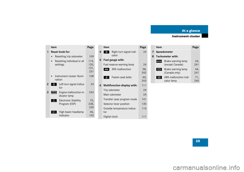
Instrument cluster
Item
Page
1
Reset knob for:�
Resetting trip odometer
109
�
Resetting individual or all
settings
119,
120,
131,
231
�
Instrument cluster illumi-
nation
108
2
L
Left turn signal indica-
tor
24
3
?
Engine malfunction in-
dicator lamp
243
v
Electronic Stability
Program (ESP)
75,
238,
239
A
High beam headlamp
indicator
46,
103
Item
Page
4
K
Right turn signal indi-
cator
24
5
Fuel gauge with:Fuel reserve warning lamp
24
1
SRS malfunction
58,
242
<
Fasten seat belts
60,
243
6
Multifunction display with:
111
Trip odometer
24
Main odometer
24
Transfer case program mode
141
Selector lever position
135
Outside temperature indica-
tor
110
Digital clock
111
Item
Page
7
Speedometer
8
Tachometer with:;
Brake warning lamp
(except Canada)
44,
241
3
Brake warning lamp
(Canada only)
44,
241
-
ABS malfunction indi-
cator lamp
71,
240
Page 108 of 360
.
1Reset knob
Th")
108 Controls in detailInstrument cluster
Instrument clusterA full view illustration of the instrument
cluster can be found in the “At a glance”
section of this manual (
�page 24).
1Reset knob
The instrument cluster is activated when
you:
�
open a door
�
turn on the ignition
�
press reset knob1
�
switch on the exterior lamps
You can change the instrument cluster set-
tings in the Instrument cluster submenu of
the control system (
�page 122).
Instrument cluster illumination
Use the reset knob to adjust the illumina-
tion brightness for the instrument cluster.
To brighten illumination�
Turn reset knob1 in the instrument
cluster clockwise.
The instrument cluster illumination will
brighten.To dim illumination
�
Turn reset knob1 in the instrument
cluster counterclockwise.
The instrument cluster illumination will
dim.
Coolant temperature display
iThe instrument cluster illumination is
dimmed or brightened automatically to
suit ambient light conditions.
The instrument cluster illumination will
also be adjusted automatically when
you switch on the vehicle’s exterior
lamps.
Warning!
G
�
Driving when your engine is badly over-
heated can cause some fluids which
may have leaked into the engine com-
partment to catch fire. You could be se-
riously burned
�
Steam from an overheated engine can
cause serious burns and can occur just
by opening the engine hood. Stay away
f r o m t h e e n g i n e i f y o u s e e o r h e a r s t e a m
coming from it.
Turn off the engine, get out of the vehicle
and do not stand near the vehicle until it
cools down.
Page 111 of 360

111 Controls in detail
Control system
Control system
The control system is activated as soon as
the key in the starter switch is turned to
position1. The control system enables you
to�
call up information about your vehicle
�
change vehicle settings
For example, you can use the control sys-
tem to find out when your vehicle is next
due for service, to set the language for
messages in the instrument cluster display
and much more.
The control system relays information to
the multifunction display.
Multifunction display
1Trip odometer
2Main odometer
3Outside temperature
4Clock
1
5Current gear selector lever position
6Transfer case program mode
Warning!
G
A driver’s attention to the road and traffic
conditions must always be his /her primary
focus when driving.
For your safety and the safety of others, se-
lecting features through the multifunction
steering wheel should only be done by the
driver when traffic and road conditions per-
mit it to be done safely.
Bear in mind that at a speed of just 30 mph
(approximately 50 km/h), your vehicle is
covering a distance of 44 feet (approximate-
ly 13.5 m) every second.
1See separate operating instructions for the
COMAND system for clock setting.
Page 296 of 360

296 Practical hintsBatteryDisconnecting the battery�
Turn off all electrical consumers.
�
Disconnect the battery negative lead.
�
Remove the cover from the positive ter-
minal.
�
Disconnect the battery positive lead.
�
Remove the breather hose from the
battery.
Reconnecting the battery�
Turn off all electrical consumers.
�
Connect the positive lead and fasten its
cover.
�
Connect the negative lead.
�
Install the breather hose.
!Never loosen or detach battery termi-
nal clamps while the engine is running
or the key is in the starter switch. Oth-
erwise the alternator and other elec-
tronic components could be severely
damaged.
iWith a disconnected battery�
you will no longer be able to turn
the key in the starter switch
�
the selector lever will remain
locked in positionP
!Never invert the terminal connections.!The battery, its filler caps and the vent
tube must always be securely installed
when the vehicle is in operation.
iThe following procedures must be car-
ried out following any interruption of
battery power (e.g. due to reconnec-
tion):�
Set the clock (see COMAND opera-
tor’s manual).
�
Resynchronize the front seat head
restraints and seat adjustment fore,
aft (
�page 93).
�
Resynchronize the ESP
(�page 257).
Page 334 of 360

334 IndexCHECK ENGINE malfunction indicator
lamp 243
Checking
Coolant level 215, 220
Oil level 215, 217, 218
Checklist
Off-road driving 205
Child safety 63
Infant and child restraint systems 54,
60, 63
LATCH child seat mounts 68
Child safety switch see Blocking of rear
door window operation 69
Cigarette lighter 181
Cleaning
Cup holder 235
Gear selector lever 235
Hard plastic trim items 236
Headlamps 148
Headliner 236
Illuminated door sill panels 236
Instrument cluster 235
Leather upholstery 236
Light alloy wheels 235
MB Tex upholstery 236
Plastic and rubber parts 236Rear Park Assist sensors* 234
Seat belts 236
Steering wheel 235
Windows 235
Windshield 47
Wiper blades 235
Climate control 150
Adjusting 153
Defogging windshield 153
Defrosting 154
Rear window defroster 155
Setting the temperature 152
Clock 25
Closing
Glove box 176
Hood 217
Side windows 158
Sliding/pop-up roof 160, 276
Sliding/pop-up roof
with SmartKey 161
Tailgate 88
Windows 158
Windows with SmartKey 159
Closing sliding/pop-up roof
In an emergency 276
Cockpit 22, 325Cockpit management and data system
(COMAND) 325
COMAND 325
COMAND see separate operating
instructions
Combination switch 23, 103
High beam flasher 46, 103
Turn signals 46
Windshield wipers 47
Consumer information 322
Control and operation of
radio transmitters 210
Control system 111, 325
AUDIO menu 116
Convenience submenu 128
Display digital speedometer 116
Functions 112, 115
Instrument cluster submenu 122
Lighting submenu 124
Malfunction memory menu 118
Menus 114, 115, 327
Multifunction display 111
Multifunction steering wheel 112
NAVI menu 118
Selecting radio system 117
Settings menu 119