Page 206 of 399
.
Deactivating
�
Press")
206 Controls in detailDriving systemsActivating�
Press button1.
Indicator lamp 2 on the button lights
up. A loudspeaker symbol appears in
the multifunction display (
�page 201).
Deactivating
�
Press button1.
Indicator lamp 2 on the button goes
out. No loudspeaker symbol appears in
the multifunction display.Driving with Distronic
This section describes a number of driving
situations where special precaution is re-
quired on the part of the driver. Be pre-
pared to brake in such situations. This will
deactivate the Distronic system.
Warning!
G
Distronic works to maintain the speed se-
lected by the driver unless a moving obsta-
cle proceeding directly ahead of it in the
same travel direction is detected (e.g. fol-
lowing another vehicle ahead of you at a dis-
tance set by Distronic). This means that:�
your vehicle can pass another vehicle af-
ter you change lanes
�
while in a sharp turn or if the vehicle in
front is in a sharp turn, Distronic could
lose sight of a vehicle traveling in front
of it, then your vehicle could accelerate
to the previously selected speed.
Distronic regulates only the distance be-
tween your vehicle and those directly ahead
of it, but does not register stationary objects
in the road, e.g.: �
a stopped vehicle in a traffic jam
�
a disabled vehicle
�
an oncoming vehicle
The driver must always be on the alert, ob-
serve all traffic and intercede as required by
steering or braking the vehicle.
Warning!
G
Distronic should not be used in snowy or icy
road conditions.
Page 213 of 399

213 Controls in detail
Driving systems
The Parktronic system monitors the sur-
roundings of your vehicle with six sensors
in the front bumper and four sensors in the
rear bumper.
1Sensors in the front bumperRange of the sensors
To function properly, the sensors must be
free of dirt, ice, snow and slush. Clean the
sensors regularly, being careful not to
scratch or damage the sensors.
Front sensors
Rear sensorsMinimum distance
If the system encounters an obstacle in
this range, all the warning lamps light up
and you hear a warning signal. If the obsta-
cle is closer than the minimum distance,
the actual distance may no longer be indi-
cated by the system.
Center
approx. 40 in (100 cm)
Corners
approx. 23 in (60 cm)
Center
approx. 48 in (120 cm)
Corners
approx. 32 in (80 cm)
!During parking maneuvers, pay special
attention to objects located above or
below the height of the sensors (e.g.
planters or trailer hitches). The Park-
tronic system will not detect such ob-
jects at close range and damage to
your vehicle or the object may result.
Ultrasonic signals from outside sourc-
es (e.g. truck air brakes or jackham-
mers) may impair the operation of the
Parktronic system.
Center
approx. 8 in (20 cm)
Corners
approx. 6 in (15 cm)
Page 214 of 399

214 Controls in detailDriving systemsWarning indicators
Visual signals indicate to the driver the rel-
ative distance between the sensors and an
obstacle. The warning indicator for the
front area is located above the center air
outlets in the dashboard. The warning indi-
cator for the rear area is integrated in the
rear trim.Front area warning indicator1Left side of the vehicle
2Right side of the vehicleEach warning indicator is divided into six
yellow and two red segments for either
side of the vehicle. The Parktronic system
is ready when the border around the indi-
cator is illuminated.
The position of the gear selector lever de-
termines which warning indicators will be
activated.As your vehicle approaches an object, one
or more segments will light up, depending
on the distance. When the eighth segment
lights up, you have reached the minimum
distance.
�
Front area: An intermittent acoustic
warning will sound as the seventh seg-
ment lights up and a constant acoustic
warning lasting a maximum of three
seconds will sound for the eighth seg-
ment.
�
Rear area: An intermittent acoustic
warning will sound when the first seg-
ment lights up. This signal quickens
with each additional segment lit. When
the eighth segment illuminates, the
acoustic warning becomes a constant
signal. The signal is canceled when the
selector lever is placed in position D
orP.
Selector lever po-
sition
Warning indicator
D
Front area activated
R or N
Rear area activated
P
Neither activated
Page 222 of 399
222 Controls in detailLoadingFolding front passenger seat*
Folding front passenger seat forward
1Release handle�
Press the right-hand side of release
handle1.
The handle folds out.
�
Pull the left-hand side of the release
handle.
The front passenger seat backrest is
released and can be folded forward.
�
Fold the backrest all the way forward.
�
Press the backrest lightly downward
until it is resting on the seat cushion.Folding front passenger seat back
1Release handle
�
Using release handle1, pull the back-
rest to its original position. Pull the
handle until the backrest has reached
an angle of approximatley 45°.
Warning!
G
Make sure that the backrest engages and
locks when folding it back into place.
Page 226 of 399

226 Controls in detailUseful features
Useful featuresInterior storage spaces Parcel net in front passenger footwell
A small convenience parcel net is located
in the front passenger footwell. It is for
small and light items, such as road maps,
mail, etc.Glove box
1Glove box lid release
2Compartment for mobile phone/glass-
es
Opening the glove box
�
Push lid release1.
The glove box lid opens downward.
Closing the glove box
�
Push lid up to close.
Warning!
G
To help avoid personal injury during a colli-
sion or sudden maneuver, exercise care
when stowing objects in the vehicle. Put lug-
gage or cargo in the trunk if possible. Do not
pile luggage or cargo higher than the seat
backs. Do not place anything on the shelf
below the rear window.
Luggage nets cannot secure hard or heavy
objects.
Keep compartment lids closed. This will help
to prevent stored objects from being thrown
about and injuring vehicle occupants during
an accident.
Warning!
G
The parcel net is intended for storing
light-weight items only.
Heavy objects, objects with sharp edges or
fragile objects may not be transported in the
parcel net.
The parcel net cannot protect transported
goods in the event of an accident.
Page 232 of 399
232 Controls in detailUseful featuresCigarette lighter
The cigarette lighter is located in the cen-
ter console compartment in front of the
armrest (
�page 26).
1Cigarette lighter
�
Turn key in the starter switch to
position1 or2.
�
Push in cigarette lighter1.
The lighter will pop out automatically
when hot.
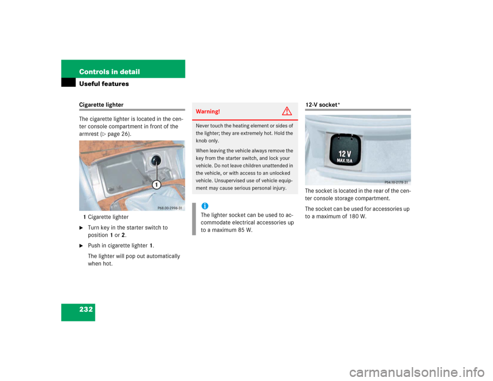
12-V socket*
The socket is located in the rear of the cen-
ter console storage compartment.
The socket can be used for accessories up
to a maximum of 180 W.
Warning!
G
Never touch the heating element or sides of
the lighter; they are extremely hot. Hold the
knob only.
When leaving the vehicle always remove the
key from the starter switch, and lock your
vehicle. Do not leave children unattended in
the vehicle, or with access to an unlocked
vehicle. Unsupervised use of vehicle equip-
ment may cause serious personal injury.iThe lighter socket can be used to ac-
commodate electrical accessories up
to a maximum 85 W.
Page 233 of 399

233 Controls in detail
Useful features
Heated steering wheel*
The control lever for the steering wheel
heating is on the lower left-hand side of the
steering wheel.
1Indicator lamp
2Heated steering wheel off
3Heated steering wheel onSwitching on
�
Check that the ignition is switched on.
All lamps in the instrument cluster light
up.
�
Turn the control lever in direction of
arrow3.
The steering wheel gets warm. The indi-
cator lamp1 lights up.
Switching off
�
Turn the control lever in direction of
arrow2.
The heated steering wheel is switched
off. The indicator lamp1 switched off.
Telephone*
Radio transmitters, such as a portable tele-
phone or a citizens band unit, should only
be used inside the vehicle if they are con-
nected to an antenna that is installed on
the outside of the vehicle.
The external antenna must be approved by
Mercedes-Benz. Please contact an autho-
rized Mercedes-Benz Center for informa-
tion on the installation of an approved
external antenna. Refer to the radio trans-
mitter operation instructions regarding use
of an external antenna.
iThe heated steering wheel do not
switch off automatically.
Warning!
G
Never operate radio transmitters equipped
with a built-in or attached antenna (i.e. with-
out being connected to an external antenna)
from inside the vehicle while the engine is
running. Doing so could lead to a malfunc-
tion of the vehicle’s electronic system, pos-
sibly resulting in an accident and personal
injury.
Page 250 of 399

250 OperationDriving instructionsPower assistance
Brakes
Warning!
G
The brake system requires electrical energy
for operation.
A malfunction in the vehicle’s power supply
or electrical system may impair brake sys-
tem operation and switch it into its
limp-home (emergency operation) mode. In
such a case, the red brake warning lamp
(�page 291) and warning messages in the
instrument cluster (
�page 303) light up
while driving. To brake, the driver must then
apply significantly greater brake pedal pres-
sure and depress the pedal much further to
obtain the expected braking effect. If neces-
sary, apply full pressure to the brake pedal.
Brakes are only applied to the front wheels.
Stopping distance is increased! If there is a
malfunction in the SBC brake system, we
recommend that the vehicle be transported
with all wheels off the ground using flatbed
or appropriate wheel lift/dolly equipment. A
tow bar must be used if circumstances do
not permit the use of the recommended
towing methods and the vehicle requires
towing with all four wheels on the ground.
Towing the vehicle with all four wheels on
the ground is only permissible for distances
up to 30 miles (50 km) and at a speed not to
exceed 30 mph (50 km/h). For more infor-
mation, refer to "Towing the vehicle"
(�page 348). For more information see
SBC brake system (
�page 77).
With the engine not running, there is no
power assistance for the steering system. In
this case, it is important to keep in mind that
a considerably higher degree of effort is nec-
essary to steer the vehicle.
Warning!
G
After driving in heavy rain for some time
without applying the brakes or through wa-
ter deep enough to wet brake components,
the first braking action may be somewhat
reduced and increased pedal pressure may
be necessary to obtain expected braking ef-
fect. Be sure to maintain a safe distance
from vehicles in front.
Resting your foot on the brake pedal will
cause excessive and premature wear of the
brake pads.