Page 102 of 394

102 Controls in detailMemory function
Memory function
The memory button and stored position
switch are located on the door.
You can store up to three different settings
per SmartKey or SmartKey with KEY-
LESS-GO*.
The following settings are saved for each
stored position:�
Driver’s seat, backrest and restraint
position
�
Settings for multicontour seat*
�
Steering wheel position
�
Driver’s side exterior rear view mirror
position
�
Passenger side exterior rear view mir-
ror position
These key dependent memory settings can
be deactivated if desired (
�page 135).1Memory button
2Stored position button
�
Be sure that the ignition is switched on
or the relevant door is open and the
SmartKey is inserted in the starter
switch.
!Prior to operating the vehicle, the driv-
er should check and adjust the seat
height, seat position fore and aft, and
seat backrest angle if necessary, to en-
sure adequate control, reach and com-
fort. The head restraint should also be
adjusted for proper height. Also see air-
bag section (
�page 57) for proper seat
positioning.
In addition, adjust the steering wheel to
ensure adequate control, reach, opera-
tion and comfort. Both the inside and
outside rear view mirrors should be ad-
justed for adequate rear vision.
Fasten seat belts. Infants and small
children should be seated in a properly
secured restraint system that complies
with U.S. Federal Motor Vehicle Safety
Standards 213 and 225 and Canadian
Motor Vehicle Safety Standards 213
and 210.2.
Warning!
G
Do not activate the memory function while
driving. Activating the memory function
while driving could cause the driver to lose
control of the vehicle.
Page 107 of 394

107 Controls in detail
Lighting
USA only
The high beam headlamps can also be ac-
tivated when driving with the daytime run-
ning lamp mode activated and exterior
lamp switch in position
M
.
To activate the daytime running lamp
mode, see “Setting daytime running lamp
mode (USA only)” (
�page 129).
Locator lighting and night security illu-
mination
Locator lighting and night security illumi-
nation are described in the control system
section, see “Setting locator lighting”
(
�page 130) and see “Setting night secu-
rity illumination (Exterior lamps delayed
shut-off)” (
�page 131).Switching on front fog lamps
�
Make sure that the low beam head-
lamps are switched on.
�
Pull out exterior lamp switch to first
stop.
The green indicator lamp
‡
in the
lamp switch lights up.Switching on rear fog lamp
�
Make sure that the low beam head-
lamps are switched on.
�
Pull out exterior lamp switch to second
stop.
The yellow indicator lamp
†
in the
lamp switch lights up.
Combination switch
The combination switch is located on the
left side of the steering column.
1High beam
2High beam flasher
iSee notes on the exterior lamp switch
(�page 105).
iFog lamps will operate with the parking
lamps and/or the low beam headlamps
on. Fog lamps should only be used in
conjunction with low beam headlamps.
Consult your State or Province Motor
Vehicle Regulations regarding allow-
able lamp operation.
Page 131 of 394

Use the
Headlamps delayed shut-off
function to set whether and for how long
you would l")
131 Controls in detail
Control system
Setting night security illumination
(Exterior lamps delayed shut-off)
Use the
Headlamps delayed shut-off
function to set whether and for how long
you would like the exterior lamps to illumi-
nate during darkness after all doors are
closed. When the delayed shut-off feature
is activated and the exterior lamp switch is
in position
U
, the following lamps will
remain lit after you remove the key from
the starter switch:
�
Parking lamps
�
Tail lamps
�
License plate lamps
�
Front fog lampsTo activate night security illumination:
�
Select delayed shut-off period (see be-
low).
�
Turn the exterior lamp switch to posi-
tion
U
.
To select delayed shut-off period:
�
Move the selection marker with
the
æ
or
ç
button to the
Light-
ing
submenu.
�
Press button
j
or
k
repeatedly
until you see this message in the dis-
play:
Headlamps delayed shut-off
.
The selection marker is on the current
setting.
�
Press
æ
or
ç
to select the de-
sired lamp-on period.You can select:
�
0 s
, the delayed shut-off feature is
deactivated
�
15 s
, 30 s
, 45 s
or
60 s
, the delayed
shut-off feature is activated
You can temporarily deactivate the de-
layed shut-off feature:
�
Before leaving the vehicle turn the key
in the starter switch to position0.
�
Then turn it to position2 and back
to0.
The delayed shut-off feature is deacti-
vated. It will reactivate as soon as you
reinsert the key in the starter switch.
For vehicles with KEYLESS-GO*:
�
Press the KEYLESS-GO start/stop but-
ton on the gear selector lever
(�page 33).
iYou can reactivate this function within
ten minutes by opening a door.
If you do not open a door after remov-
ing the key, the lamps will automatical-
ly switch off after 60 seconds.
Page 193 of 394

193 Controls in detail
Driving systems
Driving systems
The driving systems of your vehicle are de-
scribed on the following pages:�
Cruise control and Distronic*, with
which the vehicle can maintain a preset
speed
�
Parktronic*, which serves as a parking
assistant.
The BAS, ABS and ESP driving systems are
described in the “Safety and Security” sec-
tion (�page 74).
Cruise control
Cruise control automatically maintains the
speed you set for your vehicle.
Use of cruise control is recommended for
driving at a constant speed for extended
periods of time. You can set any speed
over 20 mph (30 km/h).
The cruise control function is operated by
means of the cruise control lever.
The cruise control lever is the uppermost
lever found on the left-hand side of the
steering column (
�page 20).
Warning!
G
Cruise control is a convenience system de-
signed to assist the driver during vehicle op-
eration. The driver is and must remain at all
times responsible for the vehicle speed and
for safe brake operation.
Only use cruise control if the road, traffic
and weather conditions make it advisable to
travel at a steady speed.�
The use of cruise control can be danger-
ous on winding roads or in heavy traffic
because conditions do not allow safe
driving at a steady speed.
�
The use of cruise control can be danger-
ous on slippery roads. Rapid changes in
tire traction can result in wheel spin and
loss of control.
�
Deactivate cruise control when driving
in fog.
The “Resume” function should only be oper-
ated if the driver is fully aware of the previ-
ously set speed and wishes to resume this
particular preset speed.
Page 212 of 394
212 Controls in detailLoading
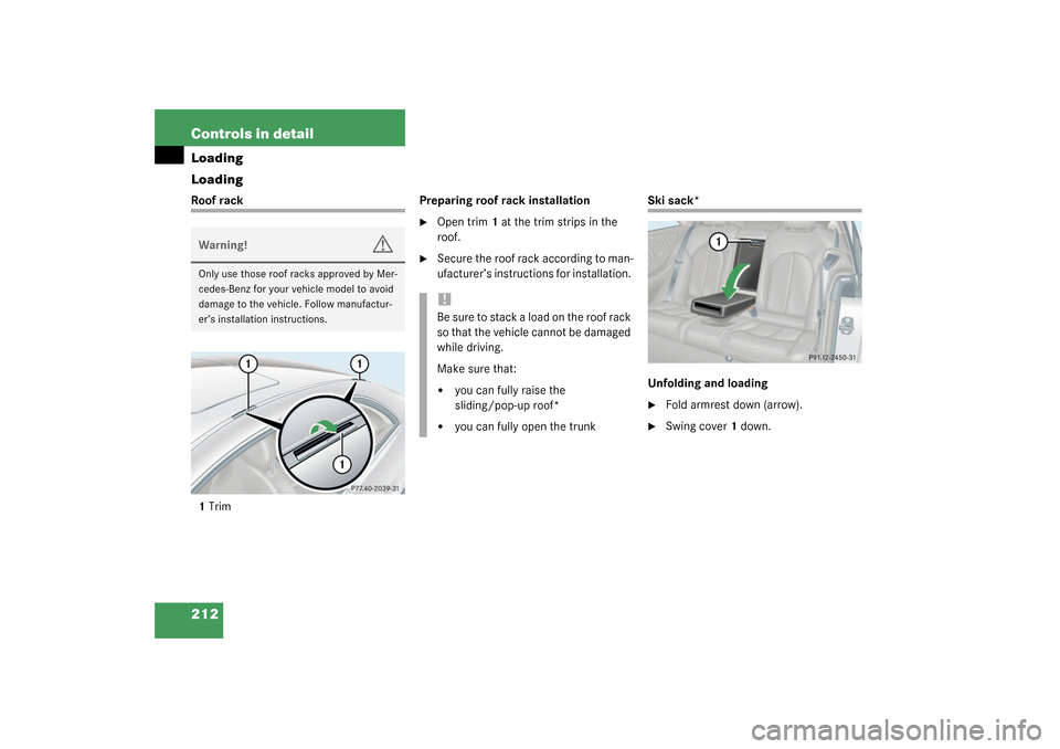
LoadingRoof rack
1TrimPreparing roof rack installation
�
Open trim1 at the trim strips in the
roof.
�
Secure the roof rack according to man-
ufacturer’s instructions for installation.
Ski sack*
Unfolding and loading�
Fold armrest down (arrow).
�
Swing cover1 down.
Warning!
G
Only use those roof racks approved by Mer-
cedes-Benz for your vehicle model to avoid
damage to the vehicle. Follow manufactur-
er’s installation instructions.
!Be sure to stack a load on the roof rack
so that the vehicle cannot be damaged
while driving.
Make sure that:�
you can fully raise the
sliding/pop-up roof*
�
you can fully open the trunk
Page 213 of 394
213 Controls in detail
Loading
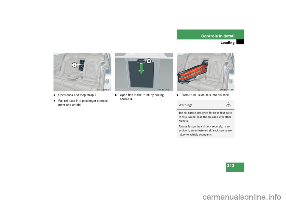
�
Open hook and loop strap2.
�
Pull ski sack into passenger compart-
ment and unfold.
�
Open flap in the trunk by pulling
handle3.
�
From trunk, slide skis into ski sack.Warning!
G
The ski sack is designed for up to four pairs
of skis. Do not load the ski sack with other
objects.
Always fasten the ski sack securely. In an
accident, an unfastened ski sack can cause
injury to vehicle occupants.
Page 215 of 394

215 Controls in detail
Loading
�
Close ski sack compartment cover.Removal of ski sack
For removal of the ski sack we recommend
that you contact an authorized
Mercedes-Benz Center.
Split rear bench seat
To expand the trunk, you can fold down the
left and right rear seat backrests.
The two sections can be folded down sep-
arately to enlarge the trunk.
Warning!
G
Never drive vehicle with trunk open while
the ski sack is removed. Deadly carbon
monoxide (CO) gases may enter vehicle in-
terior, resulting in unconsciousness and
death.iTo prevent unauthorized persons from
access to the trunk, always close the
cover.
Warning!
G
When expanding the luggage compartment,
always fold the seat cushions fully forward.
Unless you are transporting cargo, the back-
rests must remain properly locked in the up-
right position.
In an accident, during hard braking or sud-
den maneuvers, loose items will be thrown
around inside the vehicle, and cause injury
to vehicle occupants unless the items are
securely fastened in the vehicle.
Always use the cargo tie down rings
(�page 218).
Page 217 of 394

217 Controls in detail
Loading
Folding the backrest rearward
5Left locking indicator
6Right locking indicator�
Fold backrest4 rearward until it engag-
es.
�
Fold seat cushions3 rearward until
they lock into position.
If a backrest is not locked into position, a
red indicator5 or 6 will be visible.
�
Check for secure locking by pushing
and pulling on the backrest.
Loading instructions
The total load weight including vehicle oc-
cupants and luggage/cargo should not ex-
ceed the vehicle capacity weight indicated
on the certification tag which can be found
on the left door pillar.
Warning!
G
If a red indicator is visible with the backrest
up, then the backrest is not properly locked
into position.
Always lock backrest in its upright position
when rear seat bench is occupied, or the ex-
tended trunk compartment is not in use.
Check for secure locking by pushing and
pulling on the backrest.
In an accident, during hard braking or sud-
den maneuvers, loose items will be thrown
around inside the vehicle, and cause injury
to vehicle occupants unless the items are
securely fastened in the vehicle.
To help avoid personal injury during a colli-
sion or sudden maneuver, exercise care
when transporting cargo.