Page 277 of 356
277 Practical hints
Unlocking/locking in an emergency
Fuel filler flap�
Open the trunk lid.
�
Fold right-side tail lamp trim aside
�
Reach inside through opening.
�
Turn release knob1 clockwise (arrow).
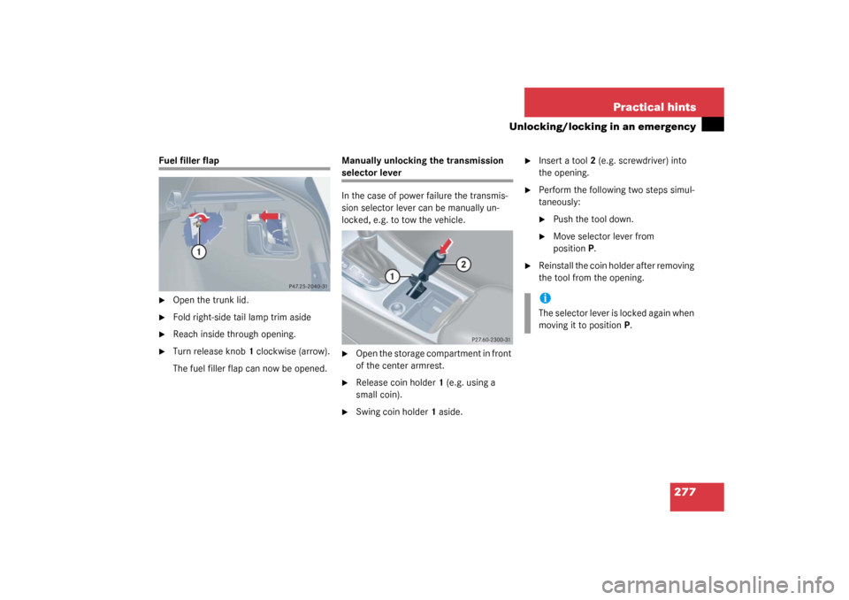
The fuel filler flap can now be opened.Manually unlocking the transmission
selector lever
In the case of power failure the transmis-
sion selector lever can be manually un-
locked, e.g. to tow the vehicle.�
Open the storage compartment in front
of the center armrest.
�
Release coin holder1 (e.g. using a
small coin).
�
Swing coin holder1 aside.
�
Insert a tool2 (e.g. screwdriver) into
the opening.
�
Perform the following two steps simul-
taneously:�
Push the tool down.
�
Move selector lever from
positionP.
�
Reinstall the coin holder after removing
the tool from the opening.iThe selector lever is locked again when
moving it to positionP.
Page 285 of 356
285 Practical hints
Replacing bulbs
Side marker lamp bulb�
Switch off the lights.
�
Carefully slide lamp towards rear.
�
Remove front end first.
�
Twist bulb socket counterclockwise
and pull out.
�
Pull bulb out of the bulb socket.
�
Insert new bulb in socket.
�
Reinstall bulb socket, push in and twist
clockwise.
�
To reinstall lamp, set rear end in
bumper and let front end snap into
place.
Replacing bulbs for rear lamps
Tail lamp assemblies�
Switch off the lights.
�
Open the trunk lid (
�page 85).
�
Turn handles2.
�
Remove the trim panel1.
�
Press together the latches1.
�
Remove bulb holder.
�
Gently push bulb into socket, turn
counterclockwise and remove.
�
Insert new bulb and reinstall bulb sock-
et.
�
Reinstall trim panel.
Page 298 of 356

298 Practical hintsJump startingThe battery is located in the engine com-
partment on the right hand side. The
terminals for jump starting are located in
front of the battery.�
Make sure that the two vehicles do not
touch.
�
Turn off the engine.
On both vehicles:
�
Turn off all electrical consumers.
�
Apply parking brake.
�
Shift selector lever to positionP (man-
ual transmission to Neutral).1Positive terminal of charged battery
2Positive under hood terminal in front of
discharged battery
3Negative terminal of charged battery
4Negative under hood terminal in front
of discharged battery
�
Connect positive terminal1 of the
charged battery with under hood
terminal2 in front of the discharged
battery with the jumper cables. Clamp
cable to charged battery1 first.
�
Start engine of the vehicle with the
charged battery and run at idle speed.
�
Connect negative terminal3 of the
charged battery with under hood
terminal4 in front of the discharged
battery with the jumper cables. Clamp
cable to charged battery3 first.
�
Start the engine of the disabled vehi-
cle.
After the engine has started, you can again
turn on the electrical consumers. Do not
turn on the lights under any circumstanc-
es.
�
Remove the jumper cables first from
negative terminals3 and4 and then
from positive terminals1 and2.
�
Have the battery checked at the
nearest authorized Mercedes-Benz
Center.
Warning!
G
Keep flames or sparks away from battery.
Do not smoke.
Observe all safety instructions and precau-
tions when handling automotive batteries
(�page 231).
!Vehicles with automatic transmission:
Do not tow-start the vehicle.
Page 299 of 356

299 Practical hints
Towing the vehicle
Towing the vehicle
Mercedes-Benz recommends that the vehi-
cle be transported with all wheels off the
ground using flatbed or appropriate wheel
lift/dolly equipment. This method is pref-
erable to other types of towing.When circumstances do not permit the
recommended towing methods, the vehi-
cle may be towed with all wheels on the
ground or front wheels raised only so far as
necessary to have the vehicle moved to a
safe location where the recommended
towing methods can be employed.
!Use flatbed or wheel lift/dolly equip-
ment with key in starter switch turned
to position0.
Do not tow with sling-type equipment.
Towing with sling-type equipment over
bumpy roads will damage radiator and
supports.
To prevent damage during transport,
do not tie down vehicle by its chassis or
suspension parts.
Switch off the tow-away alarm
(�page 79) and deactivate the auto-
matic central locking (
�page 122).
!Vehicles with automatic transmission:
Do not tow-start the vehicle.
!If the vehicle is towed with the front
axle raised, the engine must be shut off
(key in starter switch position0 or1).
Otherwise, the ESP will immediately be
engaged and will apply the rear wheel
brakes.
When towing the vehicle with all wheels
on the ground, the selector lever must
be in positionN (manual transmission:
gears disengaged) and the key must be
in starter switch position2.
When towing the vehicle with all wheels
on the ground or the front axle raised,
the vehicle may be towed only for dis-
tances up to 30 miles (50 km) and at a
speed not to exceed 30 mph
(50 km/h).
Page 300 of 356

300 Practical hintsTowing the vehicle
To be certain to avoid a possibility of
damage to the transmission, however,
we recommend the drive shaft be dis-
connected at the rear axle drive flange
for any towing beyond a short tow to a
nearby garage.
Warning!
G
If circumstances require towing the vehicle
with all wheels on the ground, always tow
with a tow bar if:�
the engine will not run
�
there is a malfunction in the power sup-
ply or in the vehicle’s electrical system
as that will be necessary to adequately con-
trol the towed vehicle.
Prior to towing the vehicle with all wheels on
the ground, make certain that the key is in
starter switch position2.
If the key is left in starter switch position0
for an extended period of time, it can no
longer be turned in the switch. In this case,
the steering is locked. To unlock, remove
key from starter switch and reinsert.
iTo signal turns while being towed with
the hazard warning flasher in use, turn
key in starter switch to position2 and
activate the combination switch for the
left or right turn signal in the usual
manner – only the selected turn signal
will operate.
Upon canceling the turn signal, the haz-
ard warning flasher will operate again.
Page 301 of 356

301 Practical hints
Towing the vehicle
Warning!
G
With the engine not running, there is no
power assistance for the braking and steer-
ing systems. In this case, it is important to
keep in mind that a considerably higher de-
gree of effort is necessary to brake and
steer the vehicle. Adapt your driving accord-
ingly.
!When towing the vehicle with all wheels
on the ground, please note the follow-
ing:
With the automatic central locking acti-
vated and the key in starter switch
position2, the vehicle doors lock if the
left front wheel as well as the right rear
wheel are turning at vehicle speeds of
approx. 9 mph (15 km/h) or more.
Switch off the tow-away alarm
(�page 79).
To prevent the vehicle doors from lock-
ing, deactivate the automatic central
locking (
�page 122).
Towing of the vehicle should only be
done using the properly installed tow-
ing eye bolt. Never attach tow cable,
tow rope or tow rod to vehicle chassis,
frame or suspension parts.
iIf the battery is disconnected or dis-
charged�
the key will not turn in the starter
switch. See notes on the battery
(�page 294) or on jump starting
(�page 297).
�
the selector lever will remain
locked in positionP. See notes on
manual unlocking of gear selector
lever (
�page 277).
Page 302 of 356
302 Practical hintsTowing the vehicleInstalling towing eye bolt
1Cover on right side of front bumper.2Cover on right side of rear bumper.To remove cover:
�
Press mark on cover in direction of ar-
row.
�
L i f t c o v e r o f f t o r e v e a l t h r e a d e d h o l e f o r
towing eye bolt.
The towing eye bolt is supplied with the
tool kit (located in the wheel well below the
trunk floor).
�
Screw towing eye bolt in to its stop and
tighten with lug wrench.
To reinstall cover:
�
Fit cover and snap into place.
Page 303 of 356
303 Practical hintsFuses
Fuses
Fuse box in passenger compartmentOpening
�
Pry cover1 open with a screw driver or
similar tool.
�
Remove cover rearward.
Closing
�
Attach the cover in the front.
�
Fold the cover in until it engages.
Fuse chart
The fuse chart is found in the fuse box in
the passenger compartment. The amper-
ages of the fuses are also given there.
Fuse box in engine compartment
The fuse box is located in the engine com-
partment on the left-hand side.
1Cover
2Screw
3Retainer
Removing/installing cover�
Twist screws2 90° counterclockwise.
�
Pull up cover1.
�
Slide out retainer3 and remove cover
by pulling towards front.
�
Install cover1 in reverse order.
iOnly install fuses that have been tested
and approved by Mercedes-Benz and
that have the specified amperage rat-
ing.
Never attempt to repair or bridge a
blown fuse. Have the cause determined
and remedied by an authorized
Mercedes-Benz Center.