Page 291 of 370
297 Practical hints
Replacing bulbs
Side marker lamp bulb�
Switch off the lights.
�
Carefully slide lamp towards rear.
�
Remove front end first.
�
Twist bulb socket counterclockwise
and pull out.
�
Pull bulb out of the bulb socket.
�
Insert new bulb in socket.
�
Reinstall bulb socket, push in and twist
clockwise.
�
To reinstall lamp, set rear end in
bumper and let front end snap into
place.
Replacing bulbs for rear lamps
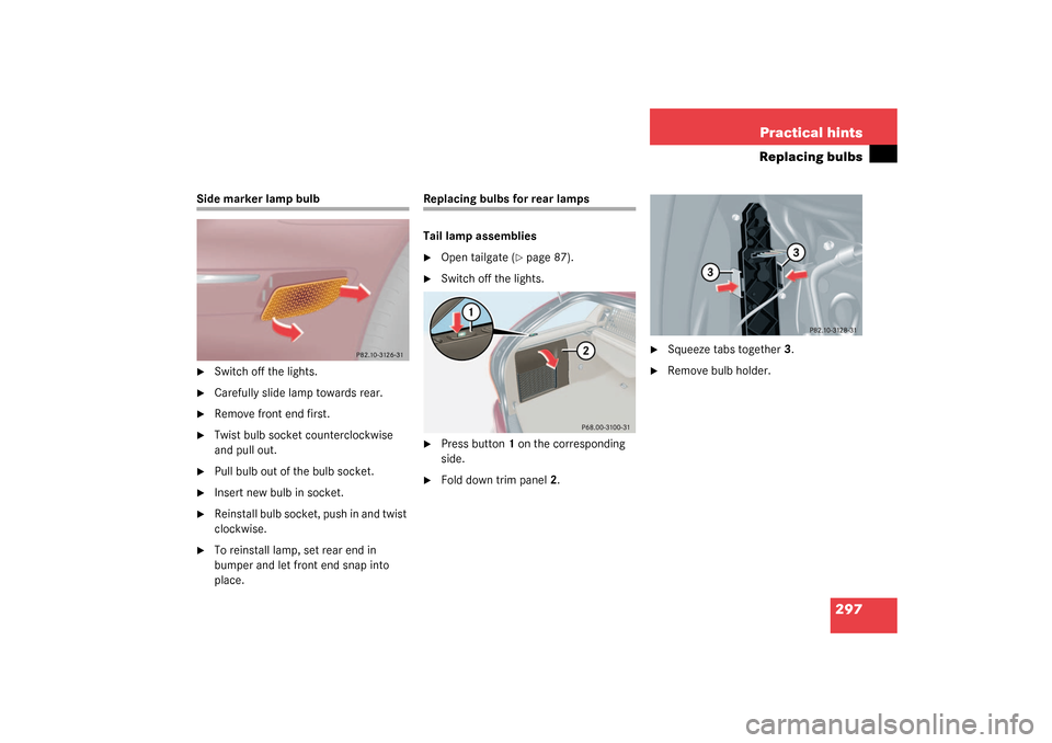
Tail lamp assemblies�
Open tailgate (
�page 87).
�
Switch off the lights.
�
Press button1 on the corresponding
side.
�
Fold down trim panel2.
�
Squeeze tabs together3.
�
Remove bulb holder.
S203 MY03_A.book Page 297 Tuesday, January 28, 2003 2:22 PM
Page 303 of 370

309 Practical hints
Jump starting
The battery is located in the engine com-
partment on the right hand side. The termi-
nals for jump starting are located in front
of the battery.�
Make sure that the two vehicles do not
touch.
�
Turn off all electrical consumers.
�
Apply parking brake.
�
Shift selector lever to positionP (man-
ual transmission to Neutral).1Positive terminal of charged battery
2Positive under hood terminal in front of
discharged battery
3Negative terminal of charged battery
4Negative under hood terminal in front
of discharged battery
�
Connect positive terminal1 of the
charged battery with the under hood
terminal2 in front of the discharged
battery with the jumper cables. Clamp
cable to charged battery1 first.
�
Start engine of the vehicle with the
charged battery and run at idle speed.
�
Connect negative terminal3 of the
charged battery with the under hood
terminal4 in front of the discharged
battery with the jumper cables. Clamp
cable to charged battery3 first.
�
Start the engine of the disabled vehi-
cle.
Now you can again turn on the electrical
consumers. Do not turn on the lights under
any circumstances.
�
Remove the jumper cables first from
negative terminals3 and4 and then
from positive terminals1 and2.
�
Have the battery checked at the near-
est authorized Mercedes-Benz Center.
Warning!
G
Keep flames or sparks away from battery.
Do not smoke.
Observe all safety instructions and precau-
tions when handling automotive batteries
(�page 239).
!Vehicles with automatic transmission
or 4MATIC*:
Do not tow-start the vehicle.
S203 MY03_A.book Page 309 Tuesday, January 28, 2003 2:22 PM
Page 304 of 370

310 Practical hintsTowing the vehicle
Towing the vehicleMercedes-Benz recommends that the
vehicle be transported with all wheels off
the ground using flatbed or appropriate
wheel lift/dolly equipment. This method is
preferable to other types of towing.When circumstances do not permit the
recommended towing methods, the
vehicle may be towed with all wheels on
the ground or front wheels raised (except
vehicles with 4MATIC*) only so far as
necessary to have the vehicle moved to a
safe location where the recommended
towing methods can be employed.
!Use flatbed or wheel lift/dolly equip-
ment with key in starter switch turned
to position0.
Do not tow with sling-type equipment.
Towing with sling-type equipment over
bumpy roads will damage radiator and
supports.
To prevent damage during transport,
do not tie down vehicle by its chassis or
suspension parts.
Switch off the tow-away alarm
(�page 80) and deactivate the auto-
matic central locking (
�page 88).
!Vehicles with automatic transmission
and/or 4MATIC*:
Do not tow-start the vehicle.!Vehicles with 4MATIC*:
Do not tow with one axle raised. Doing
so could damage the transfer case,
which is not covered by the
Mercedes-Benz Limited Warranty.
All wheels must be on or off the ground.
Observe instructions for towing the
vehicle with all wheels on the ground.
!If the vehicle is towed with the front
axle raised (not permissible for vehicles
with 4MATIC*), the engine must be
shut off (key in starter switch
position0 or1). Otherwise the ESP will
immediately be engaged and will apply
the rear wheel brakes.
When towing the vehicle with all wheels
on the ground, the selector lever must
be in positionN (manual transmission:
gears disengaged) and the key must be
in starter switch position2.
When towing the vehicle with all wheels
on the ground or the front axle raised,
the vehicle may be towed only for
distances up to 30 miles (50 km) and
at a speed not to exceed 30 mph
(50 km/h).
S203 MY03_A.book Page 310 Tuesday, January 28, 2003 2:22 PM
Page 305 of 370

311 Practical hints
Towing the vehicle
!To be certain to avoid a possibility of
damage to the drive train, however, we
recommend the drive shaft be discon-
nected at the rear axle drive flange
(vehicles with 4MATIC*: disconnected
at the front and rear axle drive flanges)
for any towing beyond a short tow to a
nearby garage.
Warning!
G
If circumstances require towing the vehicle
with all wheels on the ground, always tow
with a tow bar if:�
the engine will not run
�
there is a malfunction in the power
supply or in the vehicle’s electrical
system
as that will be necessary to adequately
control the towed vehicle.
Prior to towing the vehicle with all wheels on
the ground, make certain that the key is in
starter switch position2.
If the key is left in starter switch position0
for an extended period of time, it can no
longer be turned in the switch. In this case,
the steering is locked. To unlock, remove
key from starter switch and reinsert.
iTo signal turns while being towed with
the hazard warning flasher in use, turn
key in starter switch to position2 and
activate the combination switch for the
left or right turn signal in the usual
manner – only the selected turn signal
will operate.
Upon canceling the turn signal, the
hazard warning flasher will operate
again.
S203 MY03_A.book Page 311 Tuesday, January 28, 2003 2:22 PM
Page 306 of 370

312 Practical hintsTowing the vehicleWarning!
G
With the engine not running, there is no
power assistance for the braking and steer-
ing systems. In this case, it is important to
keep in mind that a considerably higher
degree of effort is necessary to brake and
steer the vehicle. Adapt your driving accord-
ingly.
!When towing the vehicle with all wheels
on the ground, please note the follow-
ing:
With the automatic central locking
activated and the key in starter switch
position2, the vehicle doors lock if the
left front wheel as well as the right rear
wheel are turning at vehicle speeds of
approx. 9 mph (15 km/h) or more.
Switch off the tow-away alarm
(�page 80).
To prevent the vehicle doors from
locking, deactivate the automatic
central locking (
�page 88).
Towing of the vehicle should only be
done using the properly installed
towing eye bolt. Never attach tow
cable, tow rope or tow rod to vehicle
chassis, frame or suspension parts.
iIf the battery is disconnected or
discharged�
the key will not turn in the starter
switch. See notes on the battery
(�page 305) or on jump starting
(�page 308).
�
the selector lever will remain
locked in positionP. See notes on
manual unlocking of gear selector
lever (
�page 289).
S203 MY03_A.book Page 312 Tuesday, January 28, 2003 2:22 PM
Page 307 of 370
313 Practical hints
Towing the vehicle
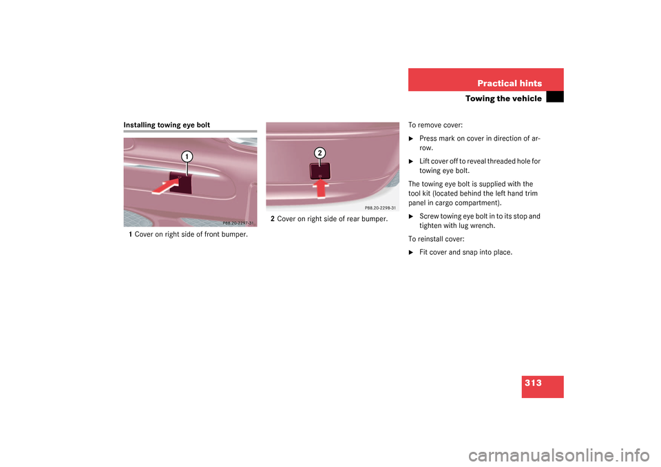
Installing towing eye bolt
1Cover on right side of front bumper.2Cover on right side of rear bumper.To remove cover:
�
Press mark on cover in direction of ar-
row.
�
Lift cover off to reveal threaded hole for
towing eye bolt.
The towing eye bolt is supplied with the
tool kit (located behind the left hand trim
panel in cargo compartment).
�
Screw towing eye bolt in to its stop and
tighten with lug wrench.
To reinstall cover:
�
Fit cover and snap into place.
S203 MY03_A.book Page 313 Tuesday, January 28, 2003 2:22 PM
Page 308 of 370
314 Practical hintsFuses
FusesFuse box in passenger compartmentOpening
�
Pull cover1 open with a screw driver or
similar tool.
�
Remove cover rearward.
Closing
�
Attach the cover in the front.
�
Fold the cover in until it engages.
Fuse chart
The fuse chart is found in the fuse box in
the passenger compartment. The amper-
ages of the fuses are also given there.
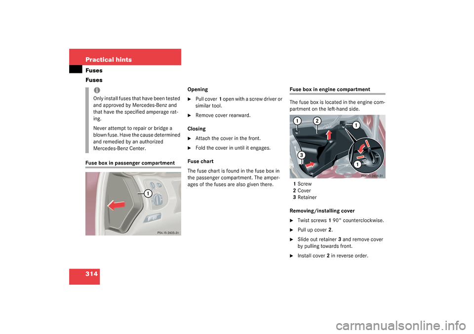
Fuse box in engine compartment
The fuse box is located in the engine com-
partment on the left-hand side.
1Screw
2Cover
3Retainer
Removing/installing cover�
Twist screws1 90° counterclockwise.
�
Pull up cover2.
�
Slide out retainer3 and remove cover
by pulling towards front.
�
Install cover2 in reverse order.
iOnly install fuses that have been tested
and approved by Mercedes-Benz and
that have the specified amperage rat-
ing.
Never attempt to repair or bridge a
blown fuse. Have the cause determined
and remedied by an authorized
Mercedes-Benz Center.
S203 MY03_A.book Page 314 Tuesday, January 28, 2003 2:22 PM
Page 339 of 370

345 Index
A
ABS 23, 73, 339
ABS control 74
Malfunction indicator lamp 255
Messages in display 261
Warning lamp 255
Accelerator position, automatic
transmission 140
Accident
In case of 50
Activating
Air circulation mode 148
Air conditioning (cooling) 150, 159
Air recirculation mode 148, 156
Anti-theft alarm system 79
Automatic climate control 153
Central locking (control system) 125
Climate control 145
Defrost 147, 156
Easy-entry/exit feature 126
ESP 77
Exterior headlamps 47
Exterior lamps 99
Exterior rear view mirror parking
position 142
Hazard warning flasher 101Headlamps 47
High beams 101
Ignition 31
Immobilizer 52, 79
Rear fog lamp 99
Rear window defroster 149, 158
Residual heat 159
Seat heater 94
Tow-away alarm 80
Windshield wipers 48
Adding
Coolant 238
Engine oil 236
Additional turn signals 292
Adjustable air vents, rear passenger
compartment 151, 160
Adjusting 32
Air distribution 147, 155
Air volume 147, 155
Backrest tilt 33, 35
Exterior rear view mirror 39
Head restraint height 33, 35, 36
Head restraint tilt 34, 35, 36
Head restraints 36
Inside rear view mirror 38
Instrument cluster illumination 104Manual seat 33
Mirrors 38
Multicontour seat* 93
Power seat 34
Rear seat head restraints 35
Seat cushion depth 93
Seat cushion tilt 33, 35
Seat fore and aft adjustment 33, 34
Seat height 33, 35
Seats 32
Steering column height 38
Steering column length 38
Steering wheel 37
Air conditioning (cooling)
Turning off 150, 159
Turning on 150, 159
Air conditioning refrigerant 330
Air distribution
Adjusting 147, 155
Air pressure see Tire inflation
pressure 242
Air recirculation mode 148, 156
Activating 148, 156
Deactivating 148, 157
Air vents, rear passenger compartment
Adjustable 151, 160
S203 MY03_A.book Page 345 Tuesday, January 28, 2003 2:22 PM