Page 23 of 376

23 At a glance
Instrument cluster
Item
Page
1
Turn signal indicator lamp,
left
47
2
Speedometer
3
Turn signal indicator lamp,
right
47
4
Fuel gauge with:Fuel reserve warning lamp
259
5
<
Seat belt nonusage
warning lamp
61,
259
1
Supplemental
restraint system
indicator lamp
56,
257
6
Multifunction display
with:
111
Trip odometer
109
Main odometer
111
Item
Page
Selector lever position
140,
141
Program mode
142
Outside temperature dis-
play
110
Digital clock
111
7
?
Engine malfunction
indicator lamp
259
v
Electronic Stability
Program (ESP)
warning lamp
75,
256
A
High beam head-
lamp indicator
47,
104
E
Indicator lamp with-
out function
1
1The indicator lamp illuminates briefly when you
turn the key in the starter switch to position2.
DTRIndicator lamp with-
out function
1
Item
Page
8
-
Antilock Brake Sys-
tem (ABS) malfunc-
tion indicator lamp
73,
257
;
Brake warning
lamp, USA only
45,
51,
258
3
Brake warning
lamp, Canada only
45,
51,
258
9
Tachometer
109
10
Reset knob for:�
Resetting trip odome-
ter
109
�
Resetting individual
settings
120
�
Instrument cluster illu-
mination
107
Page 107 of 376
.
The instrume")
107 Controls in detail
Instrument cluster
Instrument cluster
A full view illustration of the instrument
cluster can be found in the “At a glance”
section of this manual (
�page 22).
The instrument cluster is activated when
you
�
open a door
�
turn on the ignition
�
press the reset knob (
�page 22)
�
switch on the exterior lamps
You can change the instrument cluster set-
tings in the Instrument cluster submenu of
the control system (
�page 122).
Instrument cluster illumination
Use the reset knob (
�page 22) to adjust
the illumination brightness for the instru-
ment cluster.To brighten illumination
�
Turn the reset knob in the instrument
cluster clockwise (
�page 22).
The instrument cluster illumination will
brighten.
To dim illumination
�
Turn the reset knob in the instrument
cluster counterclockwise (
�page 22).
The instrument cluster illumination will
dim.
iThe instrument cluster illumination is
dimmed or brightened automatically to
suit ambient light conditions.
The instrument cluster illumination will
also be adjusted automatically when
you switch on the vehicle’s exterior
lamps.
Page 111 of 376

111 Controls in detail
Control system
Control system
The control system is activated as soon as
the key in the starter switch is turned to
position1. The control system enables you
to�
call up information about your vehicle
�
change vehicle settings
For example, you can use the control
system to find out when your vehicle is
next due for service, to set the language
for messages in the instrument cluster
display, and much more.
The control system relays information to
the multifunction display.
Multifunction display
1Outside temperature
2Main odometer
3Trip odometer
4Automatic transmission program mode
5Current gear selector lever position
6Digital clock
iThe displays for the audio systems
(radio, CD player, cassette player) will
appear in English, regardless of the
language selected.
Warning!
G
A driver’s attention to the road and traffic
conditions must always be his /her primary
focus when driving.
For your safety and the safety of others,
selecting features through the multifunction
steering wheel should only be done by the
driver when traffic and road conditions
permit it to be done safely.
Bear in mind that at a speed of just 30 mph
(approximately 50 km/h), your vehicle is
covering a distance of 44 feet
(approximately 13.5 m) every second.
Page 281 of 376
281 Practical hints
Where will I find ...?
�
Push the crank handle up.
Operational position�
Turn the crank handle clockwise until it
engages (operational position).
Before storing the vehicle jack in its
compartment:
�
The vehicle jack should be fully
collapsed.
�
The handle must be folded in (storage
position).
Spare wheel
Your vehicle is equipped with either a
spare wheel with full size tire or a
Minispare wheel. Full size spare tire has
marking “205/55 R16” or “225/45 R17”
on sidewall. Minispare has marking
“T 125/90 R16” on sidewall. Identify the
spare tire in your vehicle and follow
appropriate instructions.
Vehicles with full size tire spare wheel
The spare wheel is located in the
compartment underneath the trunk floor.�
Lift trunk floor cover and engage trunk
floor handle in upper edge of trunk.1Tool kit
2Spare wheel
3Storage tray
Removing the spare wheel
�
Remove tool kit1.
�
Turn storage tray3 counterclockwise.
�
Remove spare wheel2.
Page 282 of 376
282 Practical hintsWhere will I find ...?Storing the spare wheel�
Place spare wheel2 in wheel well.
�
Turn storage tray3 clockwise to its
stop to secure the spare wheel.
�
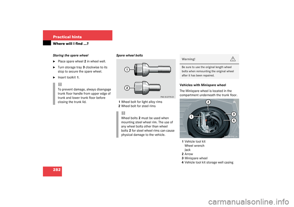
Insert toolkit1.Spare wheel bolts
1Wheel bolt for light alloy rims
2Wheel bolt for steel rimsVehicles with Minispare wheel
The Minispare wheel is located in the
compartment underneath the trunk floor.
1Vehicle tool kit
Wheel wrench
Jack
2Arrow
3Minispare wheel
4Vehicle tool kit storage well casing!To prevent damage, always disengage
trunk floor handle from upper edge of
trunk and lower trunk floor before
closing the trunk lid.
!Wheel bolts2 must be used when
mounting steel wheel rim. The use of
any wheel bolts other than wheel
bolts2 for steel wheel rims can cause
physical damage to the vehicle.
Warning!
G
Be sure to use the original length wheel
bolts when remounting the original wheel
after it has been repaired.
Page 283 of 376
 in the")
283 Practical hints
Where will I find ...?
Removing the Minispare wheel�
Lift trunk floor cover and engage trunk
floor handle in upper edge of trunk.
�
Loosen the retaining screw
(�page 279) in the middle of storage
well casing.
�
Remove the storage well casing.
�
Remove vehicle tool kit storage well
casing4.
�
Remove Minispare wheel3.
Storing the Minispare wheel
�
Place Minispare wheel3 in wheel well.
�
Place vehicle tool kit storage well
casing4 over the Minispare wheel. Be
sure that the arrow2 on storage well
casing4 points in the direction of
travel.
�
Place storage well casing (
�page 279)
over the vehicle tool kit storage well
casing4 and turn the retaining screw
(
�page 279) clockwise to its stop to
secure the Minispare wheel.
iThe arrow2 on vehicle tool kit storage
well casing4 must point in the
direction of travel, otherwise you
cannot place the storage well casing
(�page 279) on top and secure the
Minispare wheel with the retaining
screw (
�page 279).
!To prevent damage, always disengage
trunk floor handle from upper edge of
trunk and lower trunk floor before
closing the trunk lid.
Warning!
G
The dimensions of the Minispare wheel are
different from those of the road wheels. As
a result, the vehicle handling characteristics
change when driving with a Minispare wheel
mounted.
The Minispare wheel should only be used
temporarily, and should be replaced with a
regular road wheel as quickly as possible.
Page 287 of 376
287 Practical hints
Unlocking/locking in an emergency
SmartKey
1Mechanical key
2Battery compartment
Replacement batteries: Lithium, type
CR 2025 or equivalent.�
Remove mechanical key1
(�page 285).
�
Insert the mechanical key in side open-
ing and push gray slide.
The battery compartment2 is un-
latched.
�
Pull the battery compartment2 out of
the key housing in direction of arrow.3Battery
4Contact spring
�
Remove the batteries.
�
Using a lint-free cloth, insert new bat-
teries under the contact spring with the
plus (+) side facing up.
�
Return battery compartment into hous-
ing until it locks into place.
Fuel filler flap�
Open trunk lid.
�
Fold away right-side tail lamp trim.
�
Reach inside through opening2.
�
Turn release knob1 clockwise (arrow).
The fuel filler flap can now be opened.
Page 289 of 376
289 Practical hints
Opening/closing in an emergency
Opening/closing in an emergency
Sliding/pop-up roof*
You can open or close the sliding/pop-up
roof manually should an electrical malfunc-
tion occur.
The sliding/pop-up roof drive is located
behind the lens1 of the interior overhead
light.�
Pry of lens1 using a flat blade screw-
driver.
�
Slide both locking tabs2 in direction of
arrow.
�
Lower rear of cover and remove.
�
Remove cover.
�
Obtain crank3.
�
Insert crank3 through hole.
�
Turn crank3 clockwise to:�
slide roof closed
�
raise roof at the rear
�
Turn crank3 counterclockwise to:�
slide roof open
�
lower roof at the rear
The sliding/pop-up roof must be resyn-
chronized after being operated manually
(
�page 192).
iDo not disconnect electrical connec-
tors.