Page 37 of 356
37
Getting started
Adjusting
Folding head restraints back�
Push lock button
1.
The head restraints will fold backward.
Placing head restraint upright
�
Pull the head restraint forward until it
locks into position.
Two different head restraint angle posi-
tions are available.
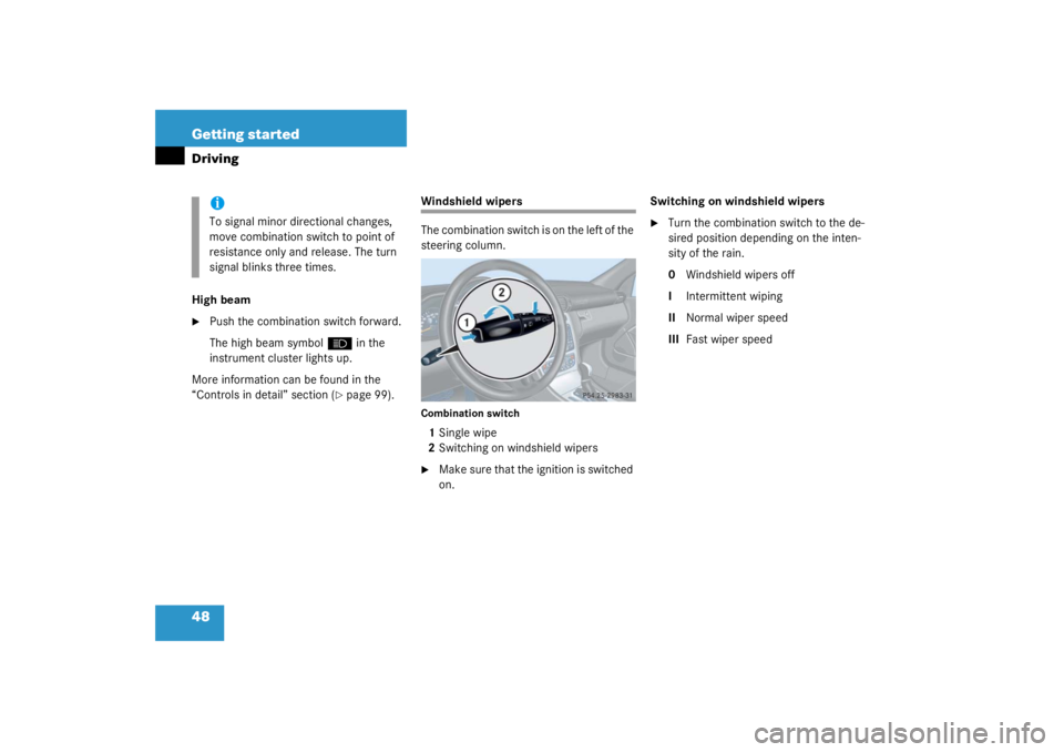
Head restraint height
1 Release knob Raising:
�
Pull up on head restraint.
If the head restraint is fully retracted,
press release knob
1 and pull the head
restraint out.
Lowering:
�
Push button 1.
�
Push down on head restraint.
Steering wheel
Warning!
G
For your protection, drive only with properly
positioned head restraints.
Adjust head restraint to support the back of
the head approximately at ear level.
Do not drive the vehicle without the seat
head restraints. Head restraints are intend-
ed to help reduce injuries during an acci-
dent.
Warning!
G
Do not adjust the steering wheel while driv-
ing. Adjusting the steering wheel while driv-
ing, or driving without the adjustment
locked could cause the driver to lose control
of the vehicle.
When leaving the vehicle, always remove the
key from the starter switch and lock your ve-
hicle.
The electrical steering wheel adjustment
feature* can also be operated with the driv-
er’s door open. Do not leave children unat-
tended in the vehicle, or with access to an
unlocked vehicle. Unsupervised use of vehi-
cle equipment may cause an accident
and/or serious personal injury.
Page 38 of 356
38 Getting startedAdjustingSteering wheel adjustment, manual1 Release handle�
To unlock the steering column, pull
handle 1 out until its stop limit.
�
Adjust the steering wheel to the de-
sired position.
�
To lock, press handle 1 all the way in
until it engages.
The steering wheel is once again
locked into position. Steering wheel adjustment, electrical*
�
Turn the key in the
starter switch to
position 1 or 2.
or
�
Open the driver’s door.
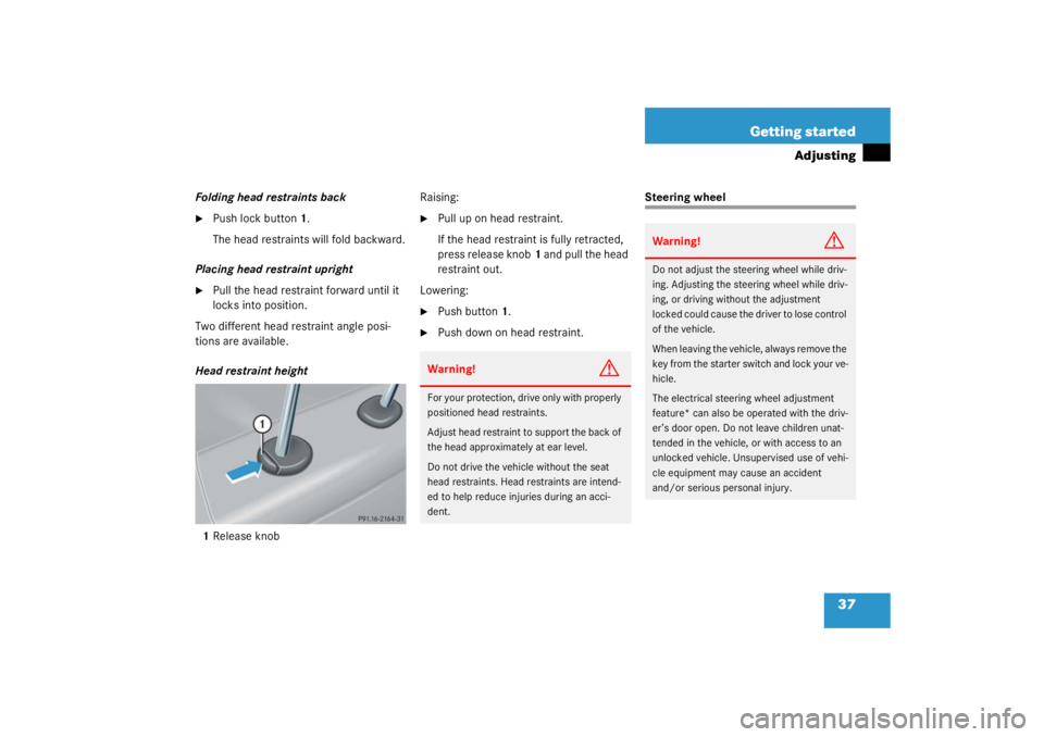
The switch is located on the steering col-
umn (lower left).
1 Steering column, lengthen or shorten
2 Steering column, height
!Do not drive the vehicle until you have
properly locked the steering column.
If the warning message
STEERING
WHEEL ADJUST - LOCK! is displayed
while the engine is running, the steer-
ing column is not locked (�page 268).
Page 39 of 356
39
Getting started
Adjusting
Steering column, lengthen or shorten�
Move stalk forward or backward in the
direction of arrow
1 until a comfortable
steering wheel position is reached with
your arms slightly bent at the elbow.
Steering column, height
�
Move stalk up or down in the direction
of arrow 2. Make sure that your legs
can move freely and that all the dis-
plays (including malfunction and indi-
cator lamps) on the instrument cluster
are clearly visible.
Mirrors
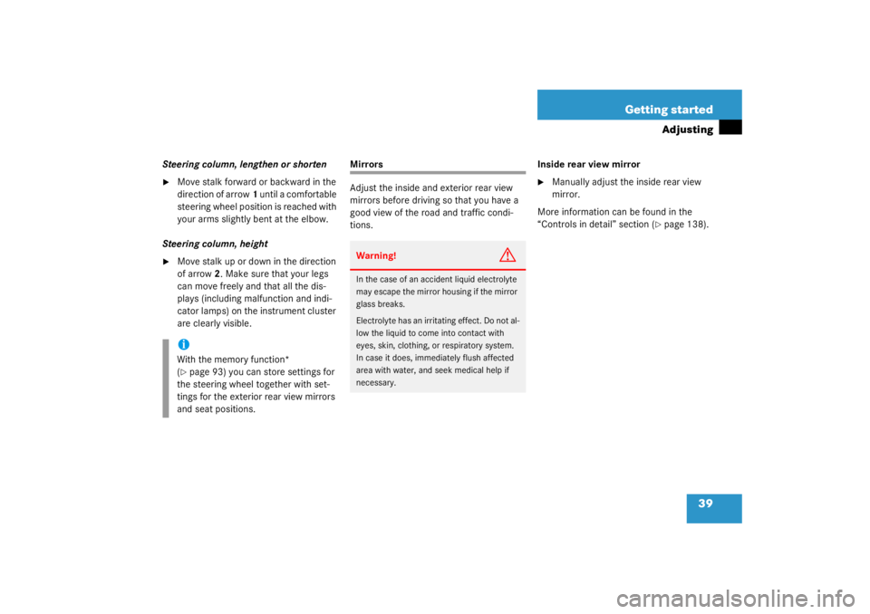
Adjust the inside and exterior rear view
mirrors before driving so that you have a
good view of the road and traffic condi-
tions. Inside rear view mirror
�
Manually adjust the inside rear view
mirror.
More information can be found in the
“Controls in detail” section (
�page 138).
iWith the memory function*
(�page 93) you can store settings for
the steering wheel together with set-
tings for the exterior rear view mirrors
and seat positions.
Warning!
G
In the case of an accident liquid electrolyte
may escape the mirror housing if the mirror
glass breaks.
Electrolyte has an irritating effect. Do not al-
low the liquid to come into contact with
eyes, skin, clothing, or respiratory system.
In case it does, immediately flush affected
area with water, and seek medical help if
necessary.
Page 40 of 356
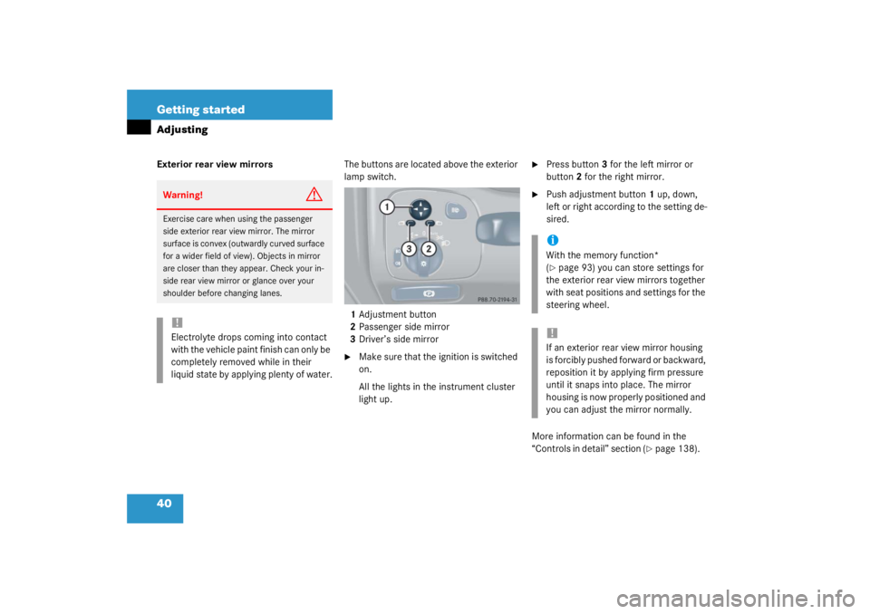
40 Getting startedAdjustingExterior rear view mirrorsThe buttons are located above the exterior
lamp switch.
1 Adjustment button
2 Passenger side mirror
3 Driver’s side mirror
�
Make sure that the ignition is switched
on.
All the lights in the instrument cluster
light up.
�
Press button 3 for the left mirror or
button 2 for the right mirror.
�
Push adjustment button 1 up, down,
left or right according to the setting de-
sired.
More information can be found in the
“Controls in detail” section (
�page 138).
Warning!
G
Exercise care when using the passenger
side exterior rear view mirror. The mirror
surface is convex (outwardly curved surface
for a wider field of view). Objects in mirror
are closer than they appear. Check your in-
side rear view mirror or glance over your
shoulder before changing lanes. !Electrolyte drops coming into contact
with the vehicle paint finish can only be
completely removed while in their
liquid state by applying plenty of water.
iWith the memory function*
(�page 93) you can store settings for
the exterior rear view mirrors together
with seat positions and settings for the
steering wheel.
!If an exterior rear view mirror housing
is forcibly pushed forward or backward,
reposition it by applying firm pressure
until it snaps into place. The mirror
housing is now properly positioned and
you can adjust the mirror normally.
Page 47 of 356

47
Getting started
Driving
More information on driving can be found
in the “Operation” section (
�page 215).
Switching on headlampsExterior lamp switch1
Off
2 Low beam headlamps on�
Turn the switch to
B
.
More information can be found in the
“Controls in detail” section (�page 96).
Turn signals and high beam
The combination switch is on the left of the
steering column.Combination switch1 Turn signals, right
2 Turn signals, left�
Press the combination switch up 1 or
down 2.
Warning!
G
Vehicles with automatic transmission: It is
dangerous to shift the selector lever out of P
or N if the engine speed is higher than idle
speed. If your foot is not firmly on the brake
pedal, the vehicle could accelerate quickly
forward or in reverse. You could lose control
of the vehicle and hit someone or some-
thing. Only shift into gear when the engine is
idling normally and when your right foot is
firmly on the brake pedal.Warning!
G
On slippery road surfaces, never downshift
in order to obtain braking action. This could
result in drive wheel slip and reduced vehi-
cle control. Your vehicle’s ABS will not pre-
vent this type of loss of control.
Page 48 of 356
48 Getting startedDrivingHigh beam�
Push the combination switch forward.
The high beam symbol
A
in the
instrument cluster lights up.
More information can be found in the
“Controls in detail” section (
�page 99).
Windshield wipers
The combination switch is on the left of the
steering column.Combination switch1 Single wipe
2 Switching on windshield wipers �
Make sure that the ignition is switched
on. Switching on windshield wipers
�
Turn the combination switch to the de-
sired position depending on the inten-
sity of the rain.
0
Windshield wipers off
I Intermittent wiping
II Normal wiper speed
III Fast wiper speed
iTo signal minor directional changes,
move combination switch to point of
resistance only and release. The turn
signal blinks three times.
Page 51 of 356

51
Getting started
Parking and locking
Parking and locking
You have now completed your first drive.
You have properly stopped and parked
your vehicle. End your drive as follows.
Parking brake
1 Release handle
2 Parking brake�
Step firmly on parking brake 2.
When the engine is running, the indica-
tor lamp
;
(USA only) or
3
(Canada only) in the instrument cluster
will be illuminated.
Warning!
G
Wait until the vehicle is stationary before re-
moving the key from the starter switch. The
vehicle cannot be steered when the key is
removed.Warning!
G
With the engine not running, there is no
power assistance for the brake and steering
system. In this case, it is important to keep
in mind that a considerably higher degree of
effort is necessary to stop or steer the vehi-
cle.
Warning!
G
Do not park this vehicle in areas where com-
bustible materials such as grass, hay or
leaves can come into contact with the hot
exhaust system, as these materials could be
ignited and cause a vehicle fire.
To reduce the risk of personal injury as a re-
sult of vehicle movement, before turning off
the engine and leaving the vehicle always:�
Keep right foot on brake pedal.
�
Firmly depress parking brake pedal.
�
Move the selector lever to position P
(manual transmission: first or reverse
gear).
�
Slowly release brake pedal.
�
When parked on an incline, turn front
wheels towards road curb.
�
Turn the key to starter switch position 0
and remove.
�
Take the key and lock vehicle when leav-
ing.
Page 57 of 356
57
Safety and Security
Occupant safety
Airbags
Warning!
G
In the event that the SRS malfunction indica-
tor lamp lights up during driving or does not
come on at all, the SRS may not be opera-
tional. For your safety, we strongly recom-
mend that you visit an authorized
Mercedes-Benz Center immediately to have
the system checked; otherwise the SRS may
not be activated when needed in an acci-
dent, which could result in serious or fatal
injury, or it might deploy unexpectedly and
unnecessarily which could also result in inju-
ry.
Improper work on the restraint systems, in-
cluding incorrect installation and removal,
can lead to possible injury through an unin-
tended activation of the SRS.
In addition, through improper work there is
a risk of rendering the SRS inoperative or
causing unintended airbag deployment.
W o r k o n t h e S R S m u s t t h e r e f o r e o n l y b e p e r -
formed by an authorized Mercedes-Benz
Center.
Warning!
G
Airbags are designed to reduce the potential
of injury in certain frontal (front airbags) im-
pacts, or side (side impact and head protec-
tion window curtain airbags) impacts which
may cause significant injuries. However, no
system available today can totally eliminate
injuries and fatalities.
The activation of the SRS temporarily releas-
es a small amount of dust from the airbags.
This dust, however, is neither injurious to
your health, nor does it indicate a fire in the
vehicle. The dust might cause some tempo-
rary breathing difficulty for people with asth-
ma or other breathing trouble. To avoid this,
you may wish to get out of the vehicle as
soon as it is safe to do so. If you have any
breathing difficulty but cannot get out of the
vehicle after the airbag inflates, then get
fresh air by opening a window or door.
Warning!
G
To reduce the risk of injury when the front
airbags inflate, it is very important for the
driver and front passenger to always be in a
properly seated position and to wear your
seat belts.
For maximum protection in the event of a
collision always be in normal seated position
with your back against the backrest. Fasten
your seat belt and ensure that it is properly
positioned on your body.
Since the airbag inflates with considerable
speed and force, a proper seating and hands
on steering wheel position will help to keep
you at a safe distance from the airbag. Oc-
cupants who are unbelted, out of position or
too close to the airbag can be seriously in-
jured by an airbag as it inflates with great
force in the blink of an eye:�
Sit properly belted in an upright position
with your back against the seat back-
rest.