2003 LINCOLN TOWN CAR air condition
[x] Cancel search: air conditionPage 10 of 272
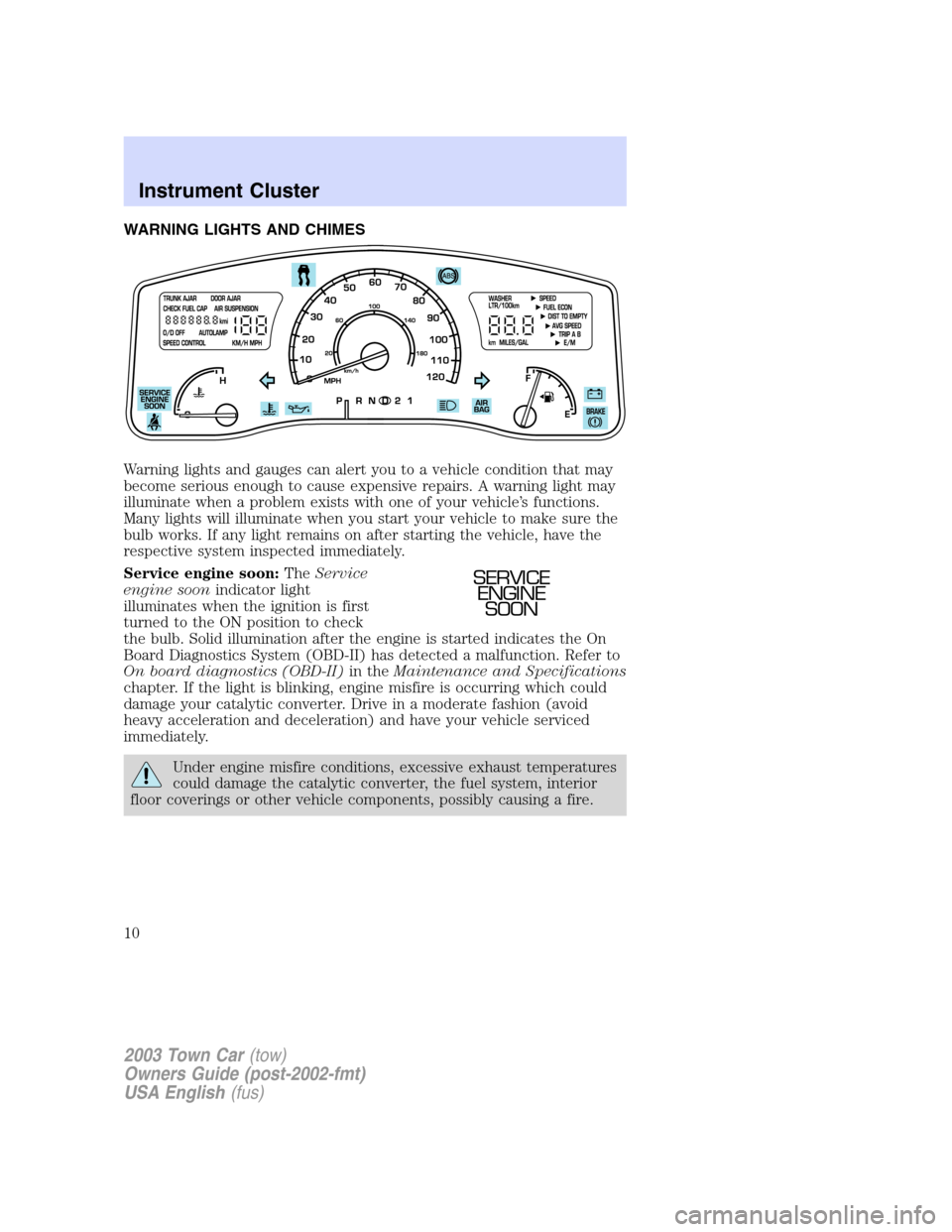
WARNING LIGHTS AND CHIMES
Warning lights and gauges can alert you to a vehicle condition that may
become serious enough to cause expensive repairs. A warning light may
illuminate when a problem exists with one of your vehicle’s functions.
Many lights will illuminate when you start your vehicle to make sure the
bulb works. If any light remains on after starting the vehicle, have the
respective system inspected immediately.
Service engine soon:TheService
engine soonindicator light
illuminates when the ignition is first
turned to the ON position to check
the bulb. Solid illumination after the engine is started indicates the On
Board Diagnostics System (OBD-II) has detected a malfunction. Refer to
On board diagnostics (OBD-II)in theMaintenance and Specifications
chapter. If the light is blinking, engine misfire is occurring which could
damage your catalytic converter. Drive in a moderate fashion (avoid
heavy acceleration and deceleration) and have your vehicle serviced
immediately.
Under engine misfire conditions, excessive exhaust temperatures
could damage the catalytic converter, the fuel system, interior
floor coverings or other vehicle components, possibly causing a fire.
SERVICE
ENGINE
SOON
2003 Town Car(tow)
Owners Guide (post-2002-fmt)
USA English(fus)
Instrument Cluster
Instrument Cluster
10
Page 66 of 272
General information
Safety information
Please read and follow all stated safety precautions. Failure to do
so may increase your risk of collision and personal injury. Ford
Motor Company shall not be liable for any damages of any type
arising from failure to follow these guidelines.
Do not attempt to service, repair or modify the system. See your Ford or
Lincoln Mercury dealer.
The driver must not attempt to operate any detailed operation of
the navigation system while the vehicle is in motion. Give full
attention to driving and to the road. Pull off the road and park in a
safe place before performing detailed operations.
If the system is used for an extended period of time with the
vehicle stationary, ensure that the engine is running to avoid
draining the battery.
Do not apply pressure to the display screen.
The navigation system is not a substitute for your personal judgement.
Route suggestions should not supersede local traffic regulations or safe
driving practices.
Do not follow route suggestions if they direct you to perform an unsafe
or illegal maneuver, would place you in an unsafe situation, or would
route you into an area that you consider unsafe.
Drivers should not rely on screen displays while their vehicle is in
motion. Let the voice guide you. If viewing is necessary, pull off the road
to a safe location.
Do not use the navigation system to locate emergency services.
For road safety reasons, the driver should program the system only when
the vehicle is stationary. Certain functions will therefore not operate
while the vehicle is in motion.
The map database DVD does not reflect road detours, closures or
construction, road characteristics such as rough road surface, slope or
grade, weight or height restrictions, traffic congestion, weather or similar
conditions.
To use the system as effectively and safely as possible, obtain up-to-date
map database DVD whenever they become available.
2003 Town Car(tow)
Owners Guide (post-2002-fmt)
USA English(fus)
Entertainment Systems
66
Page 71 of 272
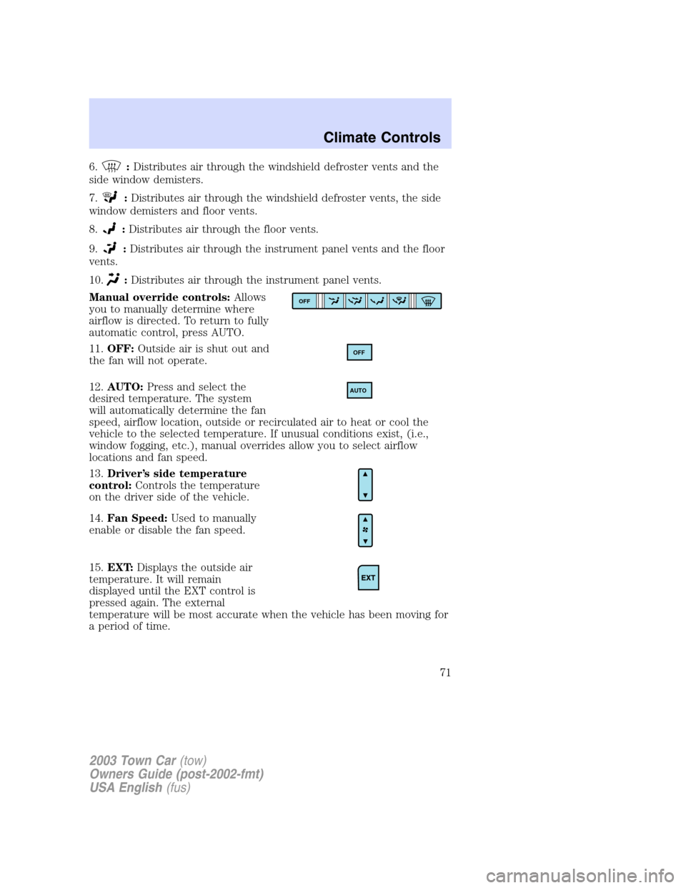
6.:Distributes air through the windshield defroster vents and the
side window demisters.
7.
:Distributes air through the windshield defroster vents, the side
window demisters and floor vents.
8.
:Distributes air through the floor vents.
9.
:Distributes air through the instrument panel vents and the floor
vents.
10.
:Distributes air through the instrument panel vents.
Manual override controls:Allows
you to manually determine where
airflow is directed. To return to fully
automatic control, press AUTO.
11.OFF:Outside air is shut out and
the fan will not operate.
12.AUTO:Press and select the
desired temperature. The system
will automatically determine the fan
speed, airflow location, outside or recirculated air to heat or cool the
vehicle to the selected temperature. If unusual conditions exist, (i.e.,
window fogging, etc.), manual overrides allow you to select airflow
locations and fan speed.
13.Driver’s side temperature
control:Controls the temperature
on the driver side of the vehicle.
14.Fan Speed:Used to manually
enable or disable the fan speed.
15.EXT:Displays the outside air
temperature. It will remain
displayed until the EXT control is
pressed again. The external
temperature will be most accurate when the vehicle has been moving for
a period of time.
OFF
OFF
AUTO
2003 Town Car(tow)
Owners Guide (post-2002-fmt)
USA English(fus)
Climate Controls
71
Page 87 of 272
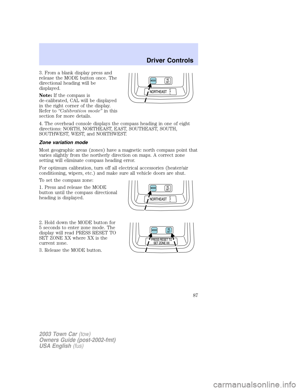
3. From a blank display press and
release the MODE button once. The
directional heading will be
displayed.
Note:If the compass is
de-calibrated, CAL will be displayed
in the right corner of the display.
Refer to“Calibration mode”in this
section for more details.
4. The overhead console displays the compass heading in one of eight
directions: NORTH, NORTHEAST, EAST, SOUTHEAST, SOUTH,
SOUTHWEST, WEST, and NORTHWEST.
Zone variation mode
Most geographic areas (zones) have a magnetic north compass point that
varies slightly from the northerly direction on maps. A correct zone
setting will eliminate compass heading error.
For optimum calibration, turn off all electrical accessories (heater/air
conditioning, wipers, etc.) and make sure all vehicle doors are shut.
To set the compass zone:
1. Press and release the MODE
button until the compass directional
heading is displayed.
2. Hold down the MODE button for
5 seconds to enter zone mode. The
display will read PRESS RESET TO
SET ZONE XX where XX is the
current zone.
3. Release the MODE button.
2003 Town Car(tow)
Owners Guide (post-2002-fmt)
USA English(fus)
Driver Controls
87
Page 133 of 272
SAFETY RESTRAINTS
Personal Safety System
The Personal Safety System provides an improved overall level of frontal
crash protection to front seat occupants and is designed to help further
reduce the risk of air bag-related injuries. The system is able to analyze
different occupant conditions and crash severity before activating the
appropriate safety devices to help better protect a range of occupants in
a variety of frontal crash situations.
Your vehicle’s Personal Safety System consists of the following items:
•Driver and passenger dual-stage air bag supplemental restraints
•Driver and front passenger side air bags
•Front safety belts with pretensioners, energy management retractors,
and safety belt usage sensors
•Driver’s seat position sensor
•Passenger occupant classification sensor
•Front crash severity sensor
•Restraints Control Module (RCM) with impact and safing sensors
•Restraint system warning light and back-up tone
•The electrical wiring for the air bags, crash sensor(s), safety belt
pretensioners, front safety belt usage sensors, driver seat position
sensor, passenger occupant classification sensor, and indicator lights
How does the personal safety system work?
The Personal safety system can adapt the deployment strategy of your
vehicle’s safety devices according to crash severity and occupant
conditions. A collection of crash and occupant sensors provides
information to the Restraints control module (RCM). During a crash, the
RCM activates the safety belt pretensioners and/or either one or both
stages of the dual-stage air bag supplemental restraints based on crash
severity and occupant conditions.
The fact that the pretensioners or air bags did not activate for both front
seat occupants in a collision does not mean that something is wrong with
the system. Rather, it means the Personal safety system determined the
accident conditions (crash severity, belt usage, etc.) were not
appropriate to activate these safety devices. Front air bags and
pretensioners are designed to activate only in frontal and near-frontal
collisions, not rollovers, side-impacts, or rear-impacts unless the collision
causes sufficient longitudinal deceleration.
2003 Town Car(tow)
Owners Guide (post-2002-fmt)
USA English(fus)
Seating and Safety Restraints
133
Page 135 of 272
designed to help protect small (child size) occupants from air bag
deployments when they are improperly seated or restrained in the front
passenger seat contrary to proper child-seating or restraint usage
recommendations. Even with this technology, parents areSTRONGLY
encouraged to always properly restrain children in the rear seat. The
sensor also turns off the air bag(s) when the passenger seat is empty to
prevent unnecessary replacement of the air bag(s) after a collision.
Front safety belt usage sensors
The front safety belt usage sensors detect whether or not the driver and
front outboard passenger safety belts are fastened. This information
allows your Personal safety system to tailor the air bag deployment and
safety belt pretensioner activation depending upon safety belt usage.
Refer toSafety beltsection in this chapter.
Front safety belt pretensioners
The safety belt pretensioners at the front outboard seating positions are
designed to tighten the safety belts firmly against the occupant’s body
during a frontal or near-frontal collision. This maximizes the effectiveness
of the safety belts and helps properly position the occupant relative to
the air bag to improve protection. The safety belt pretensioners can be
either activated alone or, if the collision is of sufficient severity, together
with the air bags.
Front safety belt energy management retractors
The front safety belt energy management retractors allow webbing to be
pulled out of the retractor in a gradual and controlled manner in
response to the occupant’s forward momentum. This helps reduce the
risk of force-related injuries to the occupant’s chest by limiting the load
on the occupant. Refer toEnergy management featuresection in this
chapter.
Determining if the Personal safety system is operational
The Personal safety system uses a warning light in the instrument cluster
or a back-up tone to indicate the condition of the system. Refer to the
Warning lightsection in theInstrument clusterchapter. Routine
maintenance of the Personal safety system is not required.
The Restraints control module (RCM) monitors its own internal circuits
and the circuits for the air bag supplemental restraints, crash sensor(s),
safety belt pretensioners, front safety belt buckle sensors, driver seat
position sensor, and passenger occupant classification sensor. In addition,
the RCM also monitors the restraints warning light in the instrument
cluster. A difficulty with the system is indicated by one or more of the
following.
2003 Town Car(tow)
Owners Guide (post-2002-fmt)
USA English(fus)
Seating and Safety Restraints
135
Page 147 of 272
Do not use extensions to change the fit of the shoulder belt
across the torso.
Safety belt maintenance
Inspect the safety belt systems periodically to make sure they work
properly and are not damaged. Inspect the safety belts to make sure
there are no nicks, tears or cuts. Replace if necessary. All safety belt
assemblies, including retractors, buckles, front seat belt buckle
assemblies, buckle support assemblies (slide bar-if equipped), shoulder
belt height adjusters (if equipped), shoulder belt guide on seatback (if
equipped), child safety seat LATCH and tether anchors, and attaching
hardware, should be inspected after a collision. Ford Motor Company
recommends that all safety belt assemblies used in vehicles involved in a
collision be replaced. However, if the collision was minor and a qualified
technician finds that the belts do not show damage and continue to
operate properly, they do not need to be replaced. Safety belt assemblies
not in use during a collision should also be inspected and replaced if
either damage or improper operation is noted.
Failure to inspect and if necessary replace the safety belt
assembly under the above conditions could result in severe
personal injuries in the event of a collision.
Refer toInteriorin theCleaningchapter.
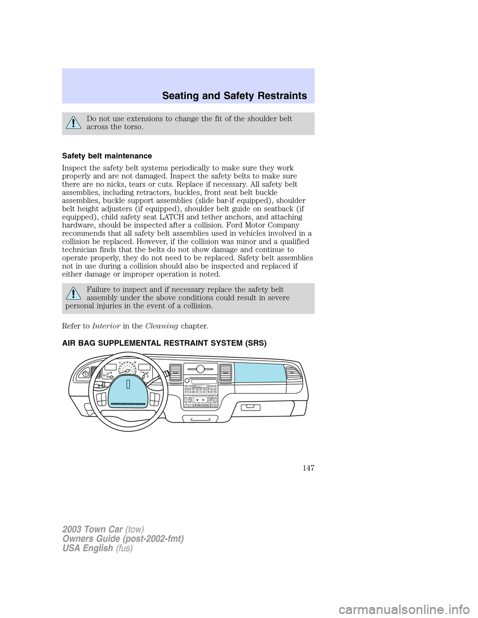
AIR BAG SUPPLEMENTAL RESTRAINT SYSTEM (SRS)
OFF
P102030405060
70
80
90
100
120206080
40100
120
160 140
180MPHkm/h110HF
E1
2FILL ON
LEFT<
CHECK
TRAC
SERVICE
ENGINE
SOON
LO
F
S
OFF
MIST
SHUF MUTE
SELBALBASS
FADETREB
SCAN CD
AM/FM
SEEKREWFF
COMP
56 34 12SIDE TUNETAPE
RDS
AUTO
SET
AUTO OFFDUAL A/C
R EXT
F/ CFF
2003 Town Car(tow)
Owners Guide (post-2002-fmt)
USA English(fus)
Seating and Safety Restraints
147
Page 151 of 272
The SRS consists of the following items:
•Driver and passenger air bag modules (which include the inflators and
air bags)
•Driver and passenger side air bags
•One or more impact and safing sensors
•A readiness light and tone
•A diagnostic module
•The electrical wiring which connects the components
The diagnostic module monitors its own internal circuits as well as the
supplemental air bag electrical system warning (including the impact
sensors), the system wiring, the air bag system readiness light, the air
bag back up power and the air bag ignitors.
Several air bag system components get hot after inflation. Do not
touch them after inflation.
If the air bag has deployed,the air bag will not function
again and must be replaced immediately.If the air bag is not
replaced, the unrepaired area will increase the risk of injury in a
collision.
If the safety belt pretensioners deploy in an accident, they will
not function again ( belt will not extract or retract) and must be
replaced immediately. Failure to replace the retractor assemblies will
increase the risk of injury.
Determining if the system is operational
The SRS uses a readiness light in the instrument cluster or a tone to
indicate the condition of the system. Refer toAir bag readinesssection
in theInstrument clusterchapter. Routine maintenance of the air bag is
not required.
A difficulty with the system is indicated by one or more of the following:
•The readiness light will either
flash or stay lit.
•The readiness light will not
illuminate immediately after
ignition is turned on.
AIR
BAG
2003 Town Car(tow)
Owners Guide (post-2002-fmt)
USA English(fus)
Seating and Safety Restraints
151