Page 61 of 288

2. Carefully pull the bulb straight out of the socket and push in the new
bulb.
3. Install the bulb socket in the lampassembly by turning it
counterclockwise.
To re-install the headlampon the vehicle:
1. Install the headlampon the vehicle by aligning the four plastic
projections into the four holes, pushing rearward to seat the lamp
assembly.
2. Insert the two retainers, making sure that the retainers go over both
plastic projections on each side of the lamp, pushing the retainers down
until they seat.
3. Replace the plastic radiator cover by inserting the edge of the cover
into the tongue and groove of the mating cover, and then rotating the
cover downward. Press firmly on the cover over each headlampand in
the center of the cover to re-engage the snap-in fasteners.
4. Turn the headlamps on and make sure they work properly.
Replacing tail/brake/turn/sidemarker/backup lamp bulbs
The tail/brake/turn/sidemarker/backupbulbs are located in the tail lamp
assembly, one just below the other. Follow the same steps to replace
each bulb:
1. Make sure the headlampswitch is
in the OFF position and then open
the liftgate to expose the lamp
assemblies.
2. Remove the two screws from the
lampassembly.
3. Pull the lampassembly towards
the rear and side of the vehicle at
an angle, carefully removing it from
the vehicle.
4. Rotate the bulb socket counterclockwise and remove from lamp
assembly.
5. Pull the bulb straight out of the socket and push in the new bulb.
6. To complete installation, follow the removal procedure in reverse
order.
Lights
61
Page 62 of 288
Replacing liftgate tail lamp bulb
1. Make sure the headlampswitch is
in the OFF position and then open
the liftgate to expose the fasteners.
2. Remove the two acorn nuts from
the lampassembly.
3. Pull the lampoff by pulling
rearward on the lamp.
4. Rotate the bulb socket
counterclockwise and carefully
remove the lampassembly.
5. Pull the bulb straight out of the
socket and push in the new bulb.
6. To complete installation, follow
the removal procedure in reverse
order.
Replacing foglamp bulbs
1. Make sure the headlampswitch is
in the OFF position and then reach
under the front of the front bumper
and remove the bulb socket from
the foglampby turning
counterclockwise.
2. Disconnect the electrical
connector from the foglampbulb.
3. Connect the electrical connector to the new foglampbulb.
4. Install the bulb socket in the foglampturning clockwise.
Lights
62
Page 63 of 288

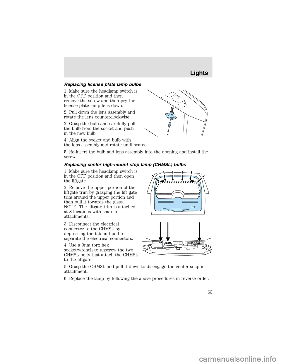
Replacing license plate lamp bulbs
1. Make sure the headlampswitch is
in the OFF position and then
remove the screw and then pry the
license plate lamp lens down.
2. Pull down the lens assembly and
rotate the lens counterclockwise.
3. Graspthe bulb and carefully pull
the bulb from the socket and push
in the new bulb.
4. Align the socket and bulb with
the lens assembly and rotate until seated.
5. Re-insert the bulb and lens assembly into the opening and install the
screw.
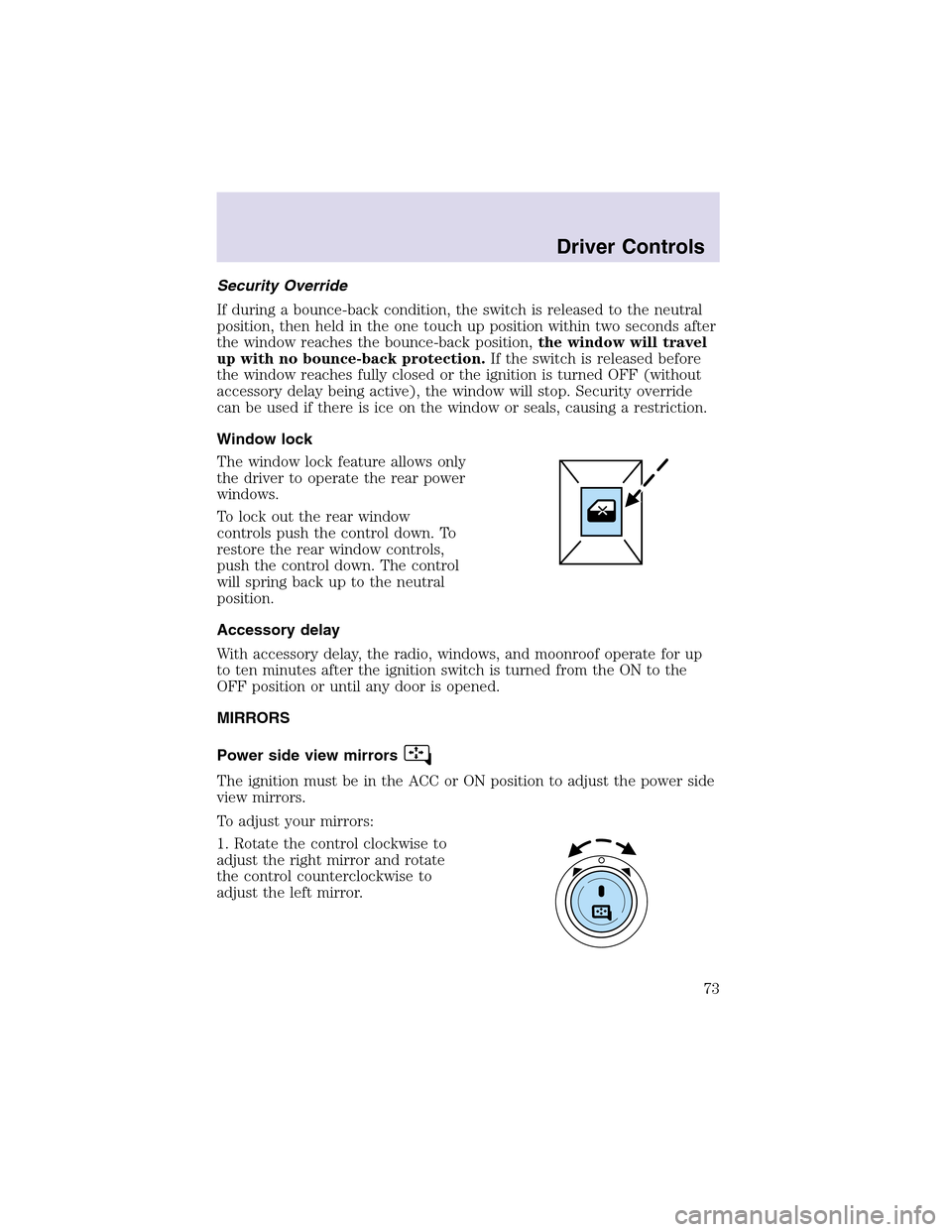
Replacing center high-mount stop lamp (CHMSL) bulbs
1. Make sure the headlampswitch is
in the OFF position and then open
the liftgate.
2. Remove the upper portion of the
liftgate trim by grasping the lift gate
trim around the upper portion and
then pull it towards the glass.
NOTE: The liftgate trim is attached
at 8 locations with snap-in
attachments.
3. Disconnect the electrical
connector to the CHMSL by
depressing the tab and pull to
separate the electrical connectors.
4. Use a 9nm torx hex
socket/wrench to unscrew the two
CHMSL bolts that attach the CHMSL
to the liftgate.
5. Grasp the CHMSL and pull it down to disengage the center snap-in
attachment.
6. Replace the lamp by following the above procedures in reverse order.
Lights
63
Page 69 of 288
CLOCK
Press the right control to increase
the time displayed.
Press the left control to decrease
the time displayed.
AUXILIARY POWER POINT(IF EQUIPPED)
Power outlets are designed for
accessory plugs only. Do not
hang any type of accessory or
accessory bracket from the plug.
Improper use of the power
outlet can cause damage not
covered by your warranty.
The auxiliary power point is located
inside the center console.
Do not plug optional electrical accessories into the cigarette
lighter. Use the power point.
An auxiliary power point is located
on the lower rear side of the center
console. The power point is
accessible from the rear seats.
Driver Controls
69
Page 73 of 288

Security Override
If during a bounce-back condition, the switch is released to the neutral
position, then held in the one touch up position within two seconds after
the window reaches the bounce-back position,the window will travel
up with no bounce-back protection.If the switch is released before
the window reaches fully closed or the ignition is turned OFF (without
accessory delay being active), the window will stop. Security override
can be used if there is ice on the window or seals, causing a restriction.
Window lock
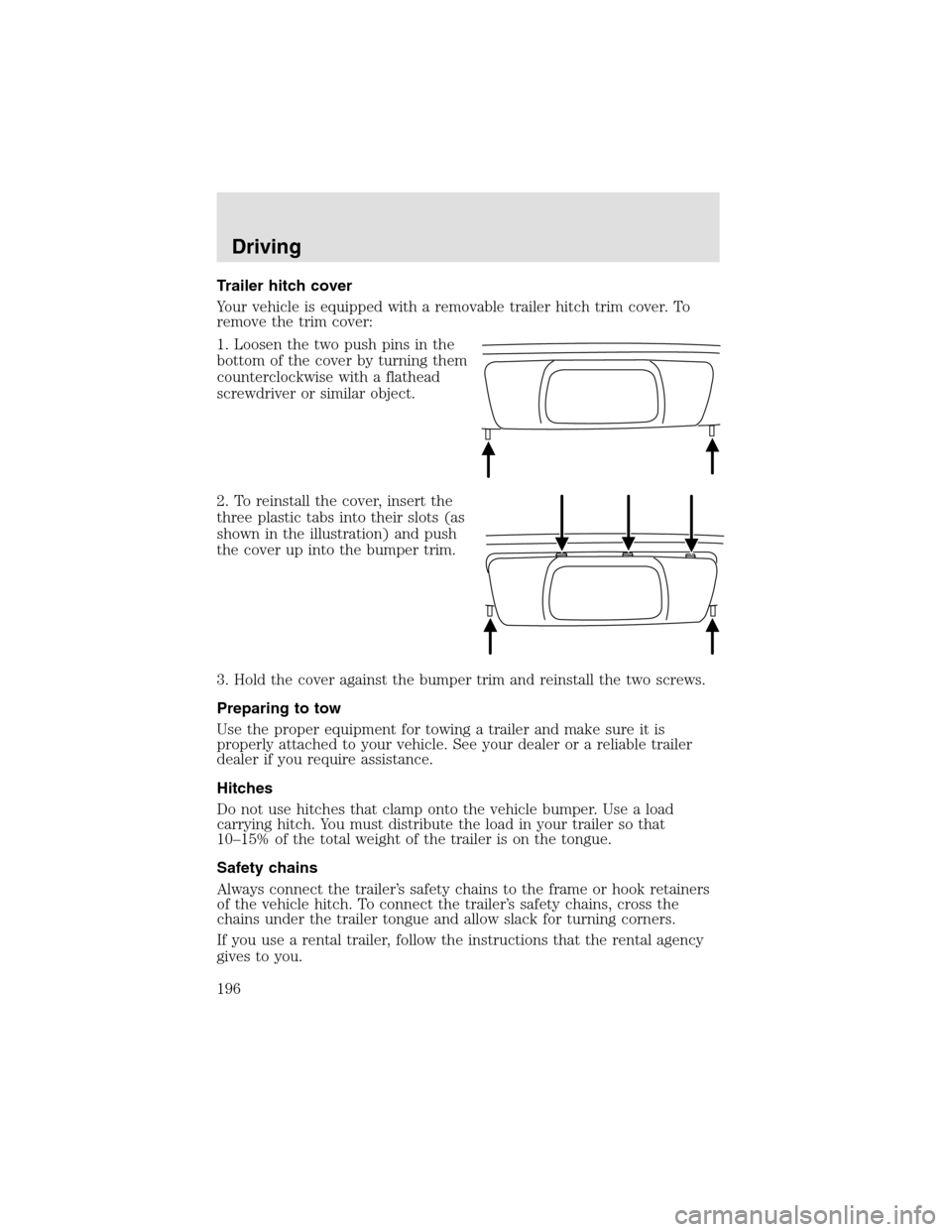
The window lock feature allows only
the driver to operate the rear power
windows.
To lock out the rear window
controls push the control down. To
restore the rear window controls,
push the control down. The control
will spring back up to the neutral
position.
Accessory delay
With accessory delay, the radio, windows, and moonroof operate for up
to ten minutes after the ignition switch is turned from the ON to the
OFF position or until any door is opened.
MIRRORS
Power side view mirrors
The ignition must be in the ACC or ON position to adjust the power side
view mirrors.
To adjust your mirrors:
1. Rotate the control clockwise to
adjust the right mirror and rotate
the control counterclockwise to
adjust the left mirror.
Driver Controls
73
Page 196 of 288

Trailer hitch cover
Your vehicle is equipped with a removable trailer hitch trim cover. To
remove the trim cover:
1. Loosen the two push pins in the
bottom of the cover by turning them
counterclockwise with a flathead
screwdriver or similar object.
2. To reinstall the cover, insert the
three plastic tabs into their slots (as
shown in the illustration) and push
the cover upinto the bumper trim.
3. Hold the cover against the bumper trim and reinstall the two screws.
Preparing to tow
Use the proper equipment for towing a trailer and make sure it is
properly attached to your vehicle. See your dealer or a reliable trailer
dealer if you require assistance.
Hitches
Do not use hitches that clamponto the vehicle bumper. Use a load
carrying hitch. You must distribute the load in your trailer so that
10–15% of the total weight of the trailer is on the tongue.
Safety chains
Always connect the trailer’s safety chains to the frame or hook retainers
of the vehicle hitch. To connect the trailer’s safety chains, cross the
chains under the trailer tongue and allow slack for turning corners.
If you use a rental trailer, follow the instructions that the rental agency
gives to you.
Driving
196
Page 205 of 288

Fuse/Relay
LocationFuse Amp
RatingPassenger Compartment Fuse
Panel Description
10 10A Heated backlight relay coil,
Climate seat modules, Auxiliary
A/C temperature blend/mode
actuator, A/C clutch relay contact
11 20A Not used (spare)
12 15A Restraints module
13 10A Brake shift interlock
14 5A Cornering lamps
15 5A Instrument cluster, Rear wiper
module, Telematics
16 15A Cigar lighter, OBD II, Liftgate
release relay coil and contacts
17 15A Delayed accessory relay coil,
Battery saver relay coil and
contacts
18 5A Not used (spare)
19 15A Washer pump
20 5A Shifter, Clock, Power mirror
switch, DVD
21 10A Brake pressure switch (ABS), IVD
switch, Flasher relay
22 10A ABS module
23 5A Sunload/Autolampsensor
(SecuriLock�transceiver LED)
24 20A Subwoofer, Navigation
25 5A Puddle lamprelay coil, Trailer tow
battery charge relay coil
26 5A SecuriLock�transceiver
27 5A Rear park assist, VAPS module,
Telematics
28 5A Radio, Navigation
29 10A DTRS, Feed to Fuse 28
Roadside Emergencies
205
Page 213 of 288
Note:Passengers should not remain
in the vehicle when the vehicle is being jacked.
4. Block the wheel that is diagonally opposite of the flat tire using the
wheel chock provided with your vehicle.
Location of the spare tire and tools
The spare tire and tools for your vehicle are stowed in the following
locations:
Tool Location
Spare tire Under the vehicle, just in front of
the rear bumper. The spare tire
winch drive nut is located at the
rear center of the cargo area
under a lid.
Jack, lug nut wrench, jack handle,
wheel chockBehind the rear seat under the
carpeted floor lid in the cargo
floor. The tools are located in a
bag attached to the jack.
Removing the jack and tools
1. Open liftgate and remove the
carpeted floor lid and jack cover.
2. Turn jack screw eyelet
counterclockwise and remove the
jack from the bracket.
Roadside Emergencies
213