2003 JEEP GRAND CHEROKEE universal joints
[x] Cancel search: universal jointsPage 46 of 2199

DIFFERENTIAL & DRIVELINE
TABLE OF CONTENTS
page page
PROPELLER SHAFT......................1
FRONT TUBE AXLE......................14
FRONT AXLE - 186FBI....................15REAR AXLE - 198RBI.....................50
REAR AXLE - 226RBA....................90
PROPELLER SHAFT
TABLE OF CONTENTS
page page
PROPELLER SHAFT
DIAGNOSIS AND TESTING................1
STANDARD PROCEDURES................3
SPECIFICATIONS........................5
SPECIAL TOOLS........................5
PROPELLER SHAFT - FRONT
REMOVAL.............................6
INSTALLATION..........................6
PROPELLER SHAFT - FRONT 4.7L
REMOVAL.............................6INSTALLATION..........................7
PROPELLER SHAFT - REAR
REMOVAL.............................7
INSTALLATION..........................7
SINGLE CARDAN UNIVERSAL JOINTS
DISASSEMBLY..........................8
ASSEMBLY.............................9
DOUBLE CARDAN UNIVERSAL JOINTS
DISASSEMBLY..........................9
ASSEMBLY............................10
PROPELLER SHAFT
DIAGNOSIS AND TESTING
VIBRATION
Tires that are out-of-round, or wheels that are
unbalanced, will cause a low frequency vibration.
(Refer to 22 - TIRES/WHEELS - DIAGNOSIS AND
TESTING)
Brake rotors that are unbalanced will cause a
harsh, low frequency vibration. (Refer to 5 - BRAKES
- DIAGNOSIS AND TESTING)Driveline vibration can also result from loose or
damaged engine mounts.
Propeller shaft vibration increases as the vehicle
speed is increased. A vibration that occurs within a
specific speed range is not usually caused by a pro-
peller shaft being unbalanced. Defective universal
joints, or an incorrect propeller shaft angle, are usu-
ally the cause of such a vibration.
WJDIFFERENTIAL & DRIVELINE 3 - 1
Page 47 of 2199

DRIVELINE VIBRATION
Drive Condition Possible Cause Correction
Propeller Shaft Noise 1) Undercoating or other foreign material
on shaft.1) Clean exterior of shaft and wash with
solvent.
2) Loose U-joint clamp screws. 2) Install new clamps and screws and
tighten to proper torque.
3) Loose or bent U-joint yoke or
excessive runout.3) Install new yoke.
4) Incorrect driveline angularity. 4) Measure and correct driveline angles.
5) Rear spring center bolt not in seat. 5) Loosen spring u-bolts and seat center
bolt.
6) Worn U-joint bearings. 6) Install new U-joint.
7) Propeller shaft damaged or out of
balance.7) Installl new propeller shaft.
8) Broken rear spring. 8) Install new rear spring.
9) Excessive runout or unbalanced
condition.9) Re-index propeller shaft, test, and
evaluate.
10) Excessive drive pinion gear shaft
runout.10) Re-index propeller shaft and evaluate.
11) Excessive axle yoke deflection. 11) Inspect and replace yoke if necessary.
12) Excessive transfer case runout. 12) Inspect and repair as necessary.
Universal Joint Noise 1) Loose U-joint clamp screws. 1) Install new clamps and screws and
tighten to proper torque.
2) Lack of lubrication. 2) Replace U-joints as necessary.
BALANCE
NOTE: Removing and re-indexing the propeller
shaft 180É relative to the yoke may eliminate some
vibrations.
If propeller shaft is suspected of being unbalanced,
it can be verified with the following procedure:
(1) Raise the vehicle.
(2) Clean all the foreign material from the propel-
ler shaft and the universal joints.
(3) Inspect the propeller shaft for missing balance
weights, broken welds, and bent areas.If the pro-
peller shaft is bent, it must be replaced.
(4) Inspect the universal joints to ensure that they
are not worn, are properly installed, and are cor-
rectly aligned with the shaft.
(5) Check the universal joint clamp screws torque.
(6) Remove the wheels and tires. Install the wheel
lug nuts to retain the brake drums or rotors.
(7) Mark and number the shaft six inches from the
yoke end at four positions 90É apart.
(8) Run and accelerate the vehicle until vibration
occurs. Note the intensity and speed the vibration
occurred. Stop the engine.(9) Install a screw clamp at position 1 (Fig. 1).
Fig. 1 CLAMP SCREW - POSITION 1
1 - CLAMP
2 - SCREWDRIVER
3 - 2 PROPELLER SHAFTWJ
PROPELLER SHAFT (Continued)
Page 53 of 2199

SINGLE CARDAN UNIVERSAL
JOINTS
DISASSEMBLY
NOTE: Individual components of cardan universal
joints are not serviceable. If worn or leaking, they
must be replaced as an assembly.
(1) Remove the propeller shaft.
(2) Tap the outside of the bearing cap assembly
with a drift to loosen snap ring.
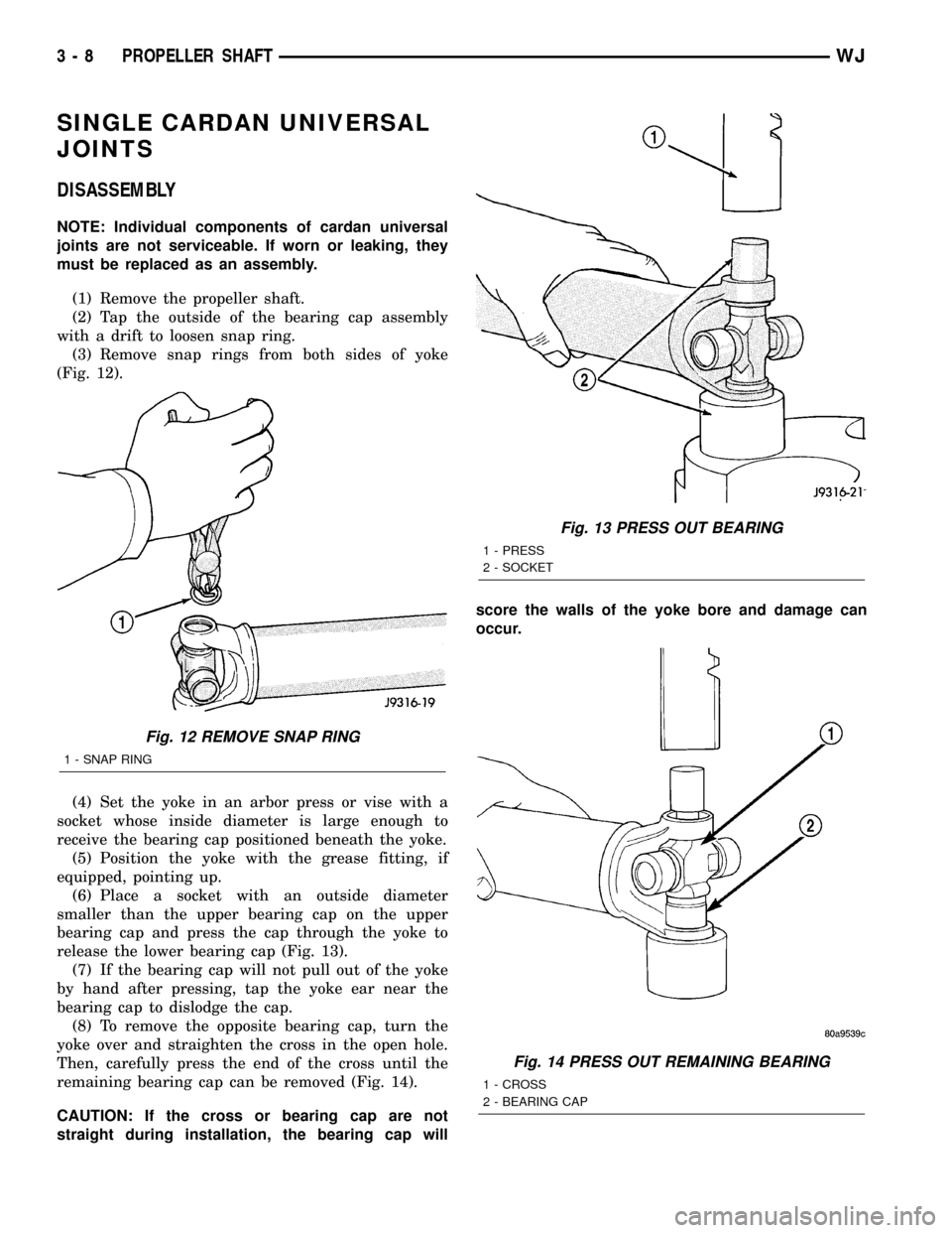
(3) Remove snap rings from both sides of yoke
(Fig. 12).
(4) Set the yoke in an arbor press or vise with a
socket whose inside diameter is large enough to
receive the bearing cap positioned beneath the yoke.
(5) Position the yoke with the grease fitting, if
equipped, pointing up.
(6) Place a socket with an outside diameter
smaller than the upper bearing cap on the upper
bearing cap and press the cap through the yoke to
release the lower bearing cap (Fig. 13).
(7) If the bearing cap will not pull out of the yoke
by hand after pressing, tap the yoke ear near the
bearing cap to dislodge the cap.
(8) To remove the opposite bearing cap, turn the
yoke over and straighten the cross in the open hole.
Then, carefully press the end of the cross until the
remaining bearing cap can be removed (Fig. 14).
CAUTION: If the cross or bearing cap are not
straight during installation, the bearing cap willscore the walls of the yoke bore and damage can
occur.
Fig. 12 REMOVE SNAP RING
1 - SNAP RING
Fig. 13 PRESS OUT BEARING
1 - PRESS
2 - SOCKET
Fig. 14 PRESS OUT REMAINING BEARING
1 - CROSS
2 - BEARING CAP
3 - 8 PROPELLER SHAFTWJ
Page 54 of 2199

ASSEMBLY
(1) Apply extreme pressure (EP) N.L.G.I. Grade 1
or 2 grease to inside of yoke bores.
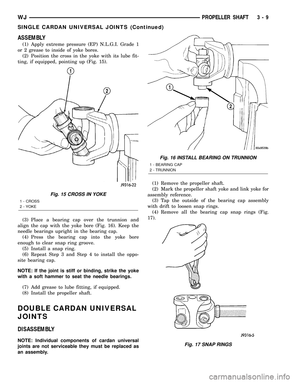
(2) Position the cross in the yoke with its lube fit-
ting, if equipped, pointing up (Fig. 15).
(3) Place a bearing cap over the trunnion and
align the cap with the yoke bore (Fig. 16). Keep the
needle bearings upright in the bearing cap.
(4) Press the bearing cap into the yoke bore
enough to clear snap ring groove.
(5) Install a snap ring.
(6) Repeat Step 3 and Step 4 to install the oppo-
site bearing cap.
NOTE: If the joint is stiff or binding, strike the yoke
with a soft hammer to seat the needle bearings.
(7) Add grease to lube fitting, if equipped.
(8) Install the propeller shaft.
DOUBLE CARDAN UNIVERSAL
JOINTS
DISASSEMBLY
NOTE: Individual components of cardan universal
joints are not serviceable they must be replaced as
an assembly.(1) Remove the propeller shaft.
(2) Mark the propeller shaft yoke and link yoke for
assembly reference.
(3) Tap the outside of the bearing cap assembly
with drift to loosen snap rings.
(4) Remove all the bearing cap snap rings (Fig.
17).
Fig. 15 CROSS IN YOKE
1 - CROSS
2 - YOKE
Fig. 16 INSTALL BEARING ON TRUNNION
1 - BEARING CAP
2 - TRUNNION
Fig. 17 SNAP RINGS
WJPROPELLER SHAFT 3 - 9
SINGLE CARDAN UNIVERSAL JOINTS (Continued)
Page 55 of 2199

(5) Remove any grease fittings if equipped.
(6) Position a socket on the press with an inside
diameter large enough to receive the bearing cap
under the link yoke.
(7)
Place another socket with an outside diameter
smaller than the bearing cap on the upper bearing cap.
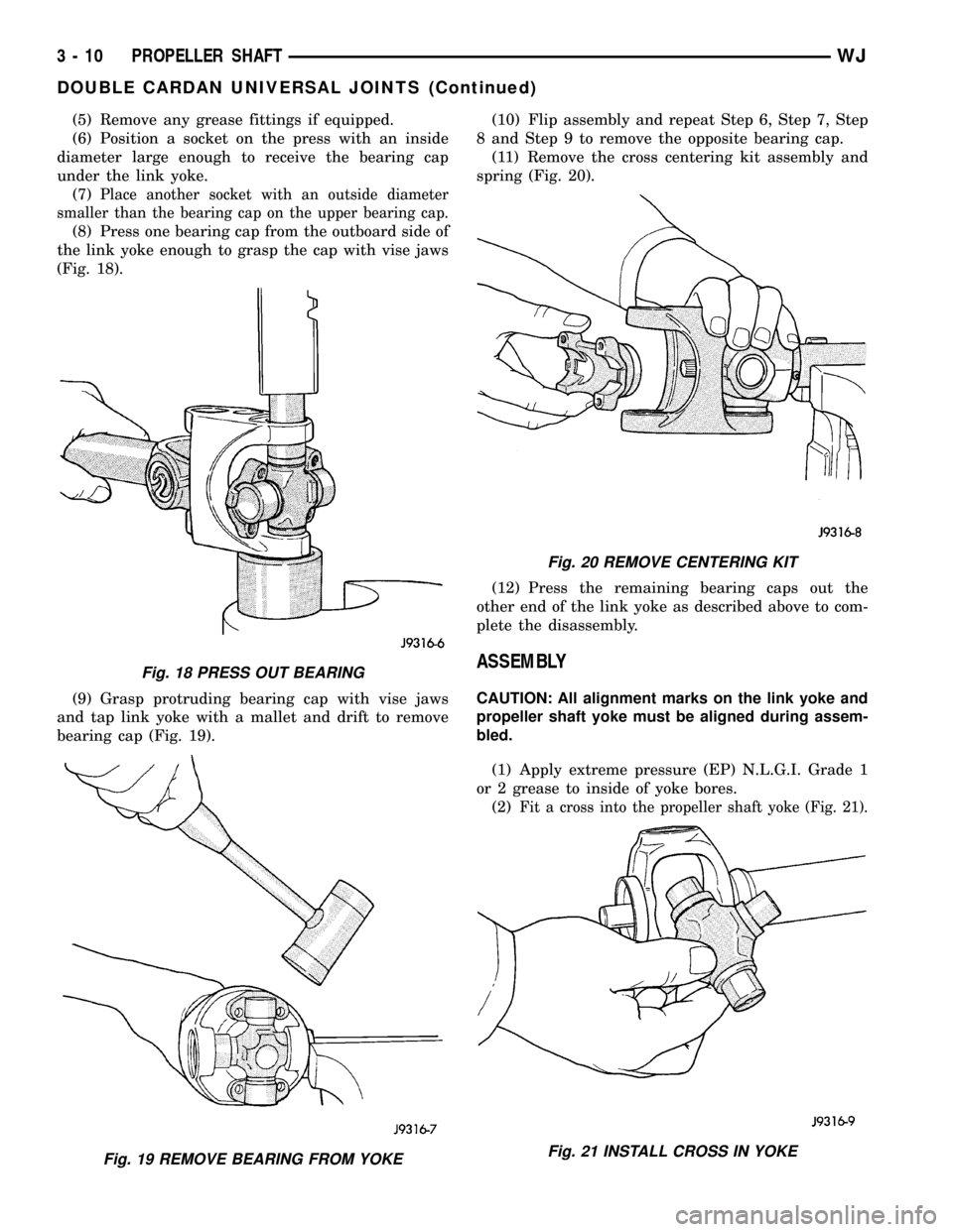
(8) Press one bearing cap from the outboard side of
the link yoke enough to grasp the cap with vise jaws
(Fig. 18).
(9) Grasp protruding bearing cap with vise jaws
and tap link yoke with a mallet and drift to remove
bearing cap (Fig. 19).(10) Flip assembly and repeat Step 6, Step 7, Step
8 and Step 9 to remove the opposite bearing cap.
(11) Remove the cross centering kit assembly and
spring (Fig. 20).
(12) Press the remaining bearing caps out the
other end of the link yoke as described above to com-
plete the disassembly.
ASSEMBLY
CAUTION: All alignment marks on the link yoke and
propeller shaft yoke must be aligned during assem-
bled.
(1) Apply extreme pressure (EP) N.L.G.I. Grade 1
or 2 grease to inside of yoke bores.
(2)
Fit a cross into the propeller shaft yoke (Fig. 21).
Fig. 18 PRESS OUT BEARING
Fig. 19 REMOVE BEARING FROM YOKE
Fig. 20 REMOVE CENTERING KIT
Fig. 21 INSTALL CROSS IN YOKE
3 - 10 PROPELLER SHAFTWJ
DOUBLE CARDAN UNIVERSAL JOINTS (Continued)
Page 56 of 2199

(3) Place a bearing cap over the trunnion and
align the cap with the yoke bore (Fig. 22). Keep nee-
dle bearings upright in the bearing cap.
(4) Press bearing cap into the yoke bore enough to
clear snap ring groove (Fig. 23).
(5) Install a snap ring.(6) Flip propeller shaft yoke and install other bear-
ing cap onto the opposite trunnion and install a snap
ring (Fig. 24).
(7) Fit the link yoke onto the remaining trunnions
and press both bearing caps into place and install
snap rings (Fig. 25).
Fig. 22 INSTALL BEARING CAP
Fig. 23 PRESS BEARING CAP
Fig. 24 PRESS BEARING CAP
Fig. 25 INSTALL LINK YOKE
WJPROPELLER SHAFT 3 - 11
DOUBLE CARDAN UNIVERSAL JOINTS (Continued)
Page 57 of 2199

(8) Install centering kit assembly inside the link
yoke (Fig. 26).
NOTE: Making sure the spring is properly posi-
tioned.
(9) Place two bearing caps on opposite trunnions of
the remaining cross. Fit the open trunnions into the
link yoke bores and the bearing caps into the center-
ing kit (Fig. 27).(10) Press the remaining two bearing caps into
place and install snap rings (Fig. 28).
(11) Tap the snap rings to seat them into the
grooves (Fig. 29).
Fig. 26 CENTERING KIT
Fig. 27 REMAINING CROSS
Fig. 28 PRESS BEARING CAP
Fig. 29 SEAT SNAP RINGS
3 - 12 PROPELLER SHAFTWJ
DOUBLE CARDAN UNIVERSAL JOINTS (Continued)
Page 58 of 2199

(12) Verify for proper assembly. Flexing the joint
beyond center, the joint should snap over-center in
both directions if correctly assembled (Fig. 30).
(13) Install the propeller shaft.
Fig. 30 VERIFY ASSEMBLY
WJPROPELLER SHAFT 3 - 13
DOUBLE CARDAN UNIVERSAL JOINTS (Continued)