2003 JEEP GRAND CHEROKEE Sump plug
[x] Cancel search: Sump plugPage 1250 of 2199
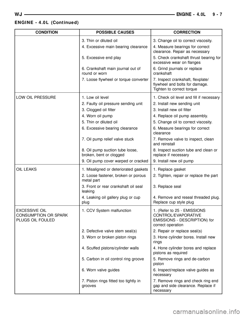
CONDITION POSSIBLE CAUSES CORRECTION
3. Thin or diluted oil 3. Change oil to correct viscosity.
4. Excessive main bearing clearance 4. Measure bearings for correct
clearance. Repair as necessary
5. Excessive end play 5. Check crankshaft thrust bearing for
excessive wear on flanges
6. Crankshaft main journal out of
round or worn6. Grind journals or replace
crankshaft
7. Loose flywheel or torque converter 7. Inspect crankshaft, flexplate/
flywheel and bolts for damage.
Tighten to correct torque
LOW OIL PRESSURE 1. Low oil level 1. Check oil level and fill if necessary
2. Faulty oil pressure sending unit 2. Install new sending unit
3. Clogged oil filter 3. Install new oil filter
4. Worn oil pump 4. Replace oil pump assembly.
5. Thin or diluted oil 5. Change oil to correct viscosity.
6. Excessive bearing clearance 6. Measure bearings for correct
clearance
7. Oil pump relief valve stuck 7. Remove valve to inspect, clean
and reinstall
8. Oil pump suction tube loose,
broken, bent or clogged8. Inspect suction tube and clean or
replace if necessary
9. Oil pump cover warped or cracked 9. Install new oil pump
OIL LEAKS 1. Misaligned or deteriorated gaskets 1. Replace gasket
2. Loose fastener, broken or porous
metal part2. Tighten, repair or replace the part
3. Front or rear crankshaft oil seal
leaking3. Replace seal
4. Leaking oil gallery plug or cup
plug4. Remove and reseal threaded plug.
Replace cup style plug
EXCESSIVE OIL
CONSUMPTION OR SPARK
PLUGS OIL FOULED1. CCV System malfunction 1. (Refer to 25 - EMISSIONS
CONTROL/EVAPORATIVE
EMISSIONS - DESCRIPTION) for
correct operation
2. Defective valve stem seal(s) 2. Repair or replace seal(s)
3. Worn or broken piston rings 3. Hone cylinder bores. Install new
rings
4. Scuffed pistons/cylinder walls 4. Hone cylinder bores and replace
pistons as required
5. Carbon in oil control ring groove 5. Remove rings and de-carbon
piston
6. Worn valve guides 6. Inspect/replace valve guides as
necessary
7. Piston rings fitted too tightly in
grooves7. Remove rings and check ring end
gap and side clearance. Replace if
necessary
WJENGINE - 4.0L 9 - 7
ENGINE - 4.0L (Continued)
Page 1536 of 2199
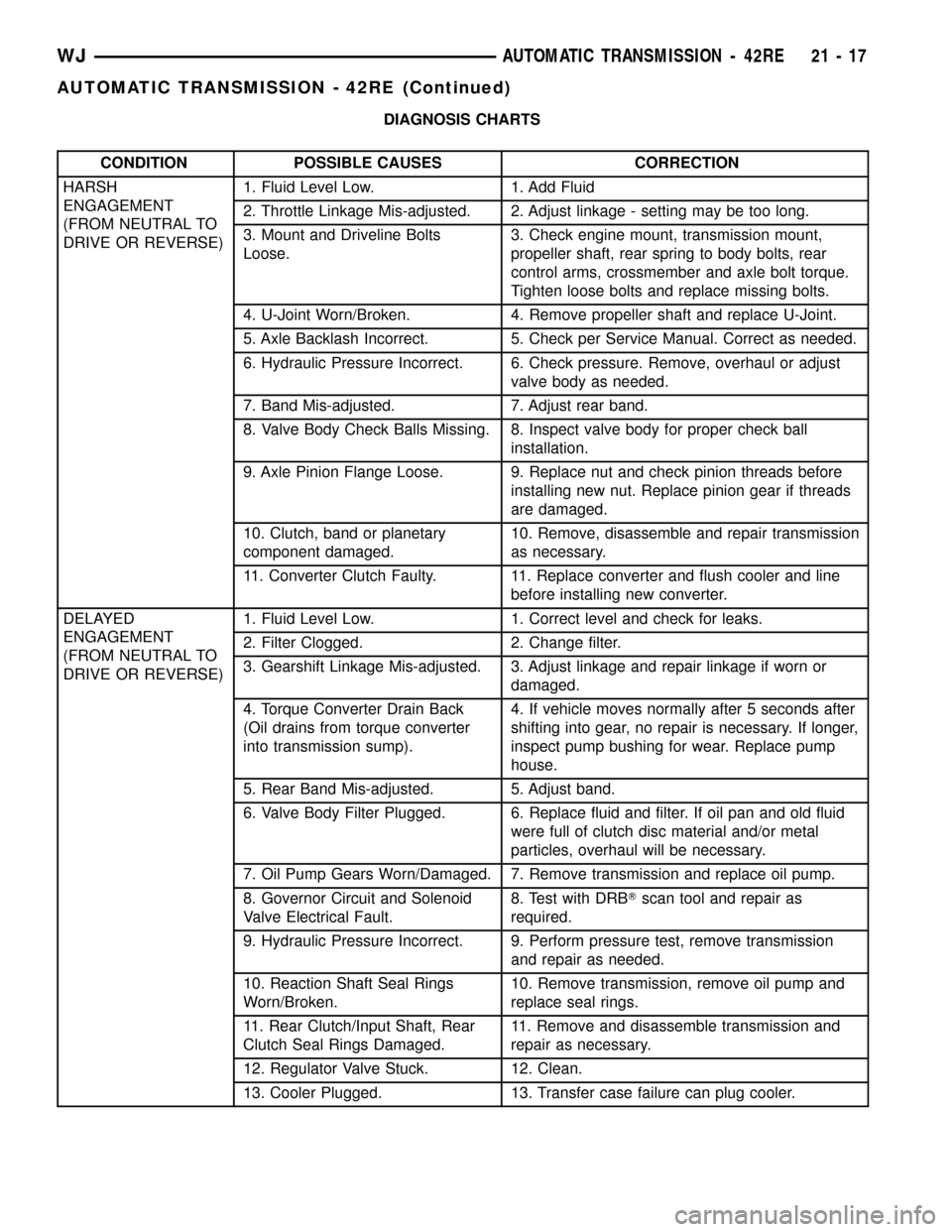
DIAGNOSIS CHARTS
CONDITION POSSIBLE CAUSES CORRECTION
HARSH
ENGAGEMENT
(FROM NEUTRAL TO
DRIVE OR REVERSE)1. Fluid Level Low. 1. Add Fluid
2. Throttle Linkage Mis-adjusted. 2. Adjust linkage - setting may be too long.
3. Mount and Driveline Bolts
Loose.3. Check engine mount, transmission mount,
propeller shaft, rear spring to body bolts, rear
control arms, crossmember and axle bolt torque.
Tighten loose bolts and replace missing bolts.
4. U-Joint Worn/Broken. 4. Remove propeller shaft and replace U-Joint.
5. Axle Backlash Incorrect. 5. Check per Service Manual. Correct as needed.
6. Hydraulic Pressure Incorrect. 6. Check pressure. Remove, overhaul or adjust
valve body as needed.
7. Band Mis-adjusted. 7. Adjust rear band.
8. Valve Body Check Balls Missing. 8. Inspect valve body for proper check ball
installation.
9. Axle Pinion Flange Loose. 9. Replace nut and check pinion threads before
installing new nut. Replace pinion gear if threads
are damaged.
10. Clutch, band or planetary
component damaged.10. Remove, disassemble and repair transmission
as necessary.
11. Converter Clutch Faulty. 11. Replace converter and flush cooler and line
before installing new converter.
DELAYED
ENGAGEMENT
(FROM NEUTRAL TO
DRIVE OR REVERSE)1. Fluid Level Low. 1. Correct level and check for leaks.
2. Filter Clogged. 2. Change filter.
3. Gearshift Linkage Mis-adjusted. 3. Adjust linkage and repair linkage if worn or
damaged.
4. Torque Converter Drain Back
(Oil drains from torque converter
into transmission sump).4. If vehicle moves normally after 5 seconds after
shifting into gear, no repair is necessary. If longer,
inspect pump bushing for wear. Replace pump
house.
5. Rear Band Mis-adjusted. 5. Adjust band.
6. Valve Body Filter Plugged. 6. Replace fluid and filter. If oil pan and old fluid
were full of clutch disc material and/or metal
particles, overhaul will be necessary.
7. Oil Pump Gears Worn/Damaged. 7. Remove transmission and replace oil pump.
8. Governor Circuit and Solenoid
Valve Electrical Fault.8. Test with DRBTscan tool and repair as
required.
9. Hydraulic Pressure Incorrect. 9. Perform pressure test, remove transmission
and repair as needed.
10. Reaction Shaft Seal Rings
Worn/Broken.10. Remove transmission, remove oil pump and
replace seal rings.
11. Rear Clutch/Input Shaft, Rear
Clutch Seal Rings Damaged.11. Remove and disassemble transmission and
repair as necessary.
12. Regulator Valve Stuck. 12. Clean.
13. Cooler Plugged. 13. Transfer case failure can plug cooler.
WJAUTOMATIC TRANSMISSION - 42RE 21 - 17
AUTOMATIC TRANSMISSION - 42RE (Continued)
Page 1659 of 2199

REGULATOR VALVE
The pressure regulator valve is needed to control
the hydraulic pressure within the system and reduce
the amount of heat produced in the fluid. The pres-
sure regulator valve is located in the valve body near
the manual valve. The pressure regulator valve train
controls the maximum pressure in the lines by
metering the dumping of fluid back into the sump.
Regulated pressure is referred to as ªline pressure.º
The regulator valve (Fig. 259) has a spring on one
end that pushes the valve to the left. This closes a
dump (vent) that is used to lower pressure. The clos-
ing of the dump will cause the oil pressure to
increase. Oil pressure on the opposite end of thevalve pushes the valve to the right, opening the
dump and lowering oil pressure. The result is spring
pressure working against oil pressure to maintain
the oil at specific pressures. With the engine run-
ning, fluid flows from the pump to the pressure reg-
ulator valve, manual valve, and the interconnected
circuits. As fluid is sent through passages to the reg-
ulator valve, the pressure pushes the valve to the
right against the large spring. It is also sent to the
reaction areas on the left side of the throttle pressure
plug and the line pressure plug. With the gear selec-
tor in the PARK position, fluid recirculates through
the regulator and manual valves back to the sump.
Fig. 259 Regulator Valve in PARK Position
21 - 140 AUTOMATIC TRANSMISSION - 42REWJ
VALVE BODY (Continued)
Page 2175 of 2199

an associated limp in will take two trips to illumi-
nate the MIL.
Refer to the Diagnostic Trouble Codes Description
Charts in this section and the appropriate Power-
train Diagnostic Procedure Manual for diagnostic
procedures.
DESCRIPTION - NON-MONITORED CIRCUITS
The PCM does not monitor the following circuits,
systems and conditions that could have malfunctions
causing driveability problems. The PCM might not
store diagnostic trouble codes for these conditions.
However, problems with these systems may cause the
PCM to store diagnostic trouble codes for other sys-
tems or components. For example, a fuel pressure
problem will not register a fault directly, but could
cause a rich/lean condition or misfire. This could
cause the PCM to store an oxygen sensor or misfire
diagnostic trouble code
FUEL PRESSURE
The fuel pressure regulator controls fuel system
pressure. The PCM cannot detect a clogged fuel
pump inlet filter, clogged in-line fuel filter, or a
pinched fuel supply or return line. However, these
could result in a rich or lean condition causing the
PCM to store an oxygen sensor or fuel system diag-
nostic trouble code.
SECONDARY IGNITION CIRCUIT
The PCM cannot detect an inoperative ignition coil,
fouled or worn spark plugs, ignition cross firing, or
open spark plug cables.
CYLINDER COMPRESSION
The PCM cannot detect uneven, low, or high engine
cylinder compression.
EXHAUST SYSTEM
The PCM cannot detect a plugged, restricted or
leaking exhaust system, although it may set a fuel
system fault.
FUEL INJECTOR MECHANICAL MALFUNCTIONS
The PCM cannot determine if a fuel injector is
clogged, the needle is sticking or if the wrong injectoris installed. However, these could result in a rich or
lean condition causing the PCM to store a diagnostic
trouble code for either misfire, an oxygen sensor, or
the fuel system.
EXCESSIVE OIL CONSUMPTION
Although the PCM monitors engine exhaust oxygen
content when the system is in closed loop, it cannot
determine excessive oil consumption.
THROTTLE BODY AIRFLOW
The PCM cannot detect a clogged or restricted air
cleaner inlet or filter element.
VACUUM ASSIST
The PCM cannot detect leaks or restrictions in the
vacuum circuits of vacuum assisted engine control
system devices. However, these could cause the PCM
to store a MAP sensor diagnostic trouble code and
cause a high idle condition.
PCM SYSTEM GROUND
The PCM cannot determine a poor system ground.
However, one or more diagnostic trouble codes may
be generated as a result of this condition. The mod-
ule should be mounted to the body at all times, also
during diagnostic.
PCM CONNECTOR ENGAGEMENT
The PCM may not be able to determine spread or
damaged connector pins. However, it might store
diagnostic trouble codes as a result of spread connec-
tor pins.
DESCRIPTION - HIGH AND LOW LIMITS
The PCM compares input signal voltages from each
input device with established high and low limits for
the device. If the input voltage is not within limits
and other criteria are met, the PCM stores a diagnos-
tic trouble code in memory. Other diagnostic trouble
code criteria might include engine RPM limits or
input voltages from other sensors or switches that
must be present before verifying a diagnostic trouble
code condition.
DESCRIPTION - LOAD VALUE
ENGINE IDLE/NEUTRAL 2500 RPM/NEUTRAL
All Engines 2% to 8% of Maximum Load 9% to 17% of Maximum Load
25 - 20 EMISSIONS CONTROLWJ
EMISSIONS CONTROL (Continued)