2003 JEEP GRAND CHEROKEE Brake
[x] Cancel search: BrakePage 1 of 2199

GROUP TAB LOCATOR
Introduction
0Lubrication & Maintenance
2Suspension
3Driveline
5Brakes
7Cooling
8AAudio
8BChime/Buzzer
8EElectronic Control Modules
8FEngine Systems
8GHeated Systems
8HHorn
8IIgnition Control
8JInstrument Cluster
8LLamps
8MMessage Systems
8NPower Systems
8ORestraints
8PSpeed Control
8QVehicle Theft Security
8RWipers/Washers
8WWiring
9Engine
11Exhaust System
13Frame & Bumpers
14Fuel System
19Steering
21Transaxle
22Tires/Wheels
23Body
24Heating & Air Conditioning
25Emissions Control
Service Manual Comment Forms (Rear of Manual)
Page 5 of 2199

FASTENER USAGE
DESCRIPTION - FASTENER USAGE
WARNING: USE OF AN INCORRECT FASTENER
MAY RESULT IN COMPONENT DAMAGE OR PER-
SONAL INJURY.
Fasteners and torque specifications references in
this Service Manual are identified in metric and SAE
format.
During any maintenance or repair procedures, it is
important to salvage all fasteners (nuts, bolts, etc.)
for reassembly. If the fastener is not salvageable, a
fastener of equivalent specification must be used.
THREADED HOLE REPAIR
DESCRIPTION - THREADED HOLE REPAIR
Most stripped threaded holes can be repaired using
a Helicoilt. Follow the vehicle or Helicoiltrecommen-
dations for application and repair procedures.
INTERNATIONAL SYMBOLS
DESCRIPTION - INTERNATIONAL SYMBOLS
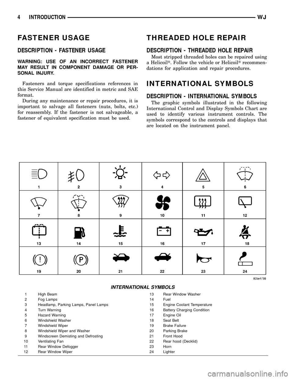
The graphic symbols illustrated in the following
International Control and Display Symbols Chart are
used to identify various instrument controls. The
symbols correspond to the controls and displays that
are located on the instrument panel.
INTERNATIONAL SYMBOLS
1 High Beam 13 Rear Window Washer
2 Fog Lamps 14 Fuel
3 Headlamp, Parking Lamps, Panel Lamps 15 Engine Coolant Temperature
4 Turn Warning 16 Battery Charging Condition
5 Hazard Warning 17 Engine Oil
6 Windshield Washer 18 Seat Belt
7 Windshield Wiper 19 Brake Failure
8 Windshield Wiper and Washer 20 Parking Brake
9 Windscreen Demisting and Defrosting 21 Front Hood
10 Ventilating Fan 22 Rear hood (Decklid)
11 Rear Window Defogger 23 Horn
12 Rear Window Wiper 24 Lighter
4 INTRODUCTIONWJ
Page 18 of 2199

JUMP STARTING
STANDARD PROCEDURE - JUMP STARTING
WARNING: REVIEW ALL SAFETY PRECAUTIONS
AND WARNINGS IN GROUP 8A, BATTERY/START-
ING/CHARGING SYSTEMS DIAGNOSTICS. DO NOT
JUMP START A FROZEN BATTERY, PERSONAL
INJURY CAN RESULT. DO NOT JUMP START WHEN
MAINTENANCE FREE BATTERY INDICATOR DOT IS
YELLOW OR BRIGHT COLOR. DO NOT JUMP
START A VEHICLE WHEN THE BATTERY FLUID IS
BELOW THE TOP OF LEAD PLATES. DO NOT
ALLOW JUMPER CABLE CLAMPS TO TOUCH
EACH OTHER WHEN CONNECTED TO A BOOSTER
SOURCE. DO NOT USE OPEN FLAME NEAR BAT-
TERY. REMOVE METALLIC JEWELRY WORN ON
HANDS OR WRISTS TO AVOID INJURY BY ACCI-
DENTAL ARCING OF BATTERY CURRENT. WHEN
USING A HIGH OUTPUT BOOSTING DEVICE, DO
NOT ALLOW BATTERY VOLTAGE TO EXCEED 16
VOLTS. REFER TO INSTRUCTIONS PROVIDED
WITH DEVICE BEING USED.
CAUTION: When using another vehicle as a
booster, do not allow vehicles to touch. Electrical
systems can be damaged on either vehicle.
TO JUMP START A DISABLED VEHICLE:
(1) Raise hood on disabled vehicle and visually
inspect engine compartment for:
²Battery cable clamp condition, clean if necessary.
²Frozen battery.
²Yellow or bright color test indicator, if equipped.
²Low battery fluid level.
²Generator drive belt condition and tension.
²Fuel fumes or leakage, correct if necessary.
CAUTION: If the cause of starting problem on dis-
abled vehicle is severe, damage to booster vehicle
charging system can result.
(2) When using another vehicle as a booster
source, park the booster vehicle within cable reach.
Turn off all accessories, set the parking brake, place
the automatic transmission in PARK or the manual
transmission in NEUTRAL and turn the ignition
OFF.
(3) On disabled vehicle, place gear selector in park
or neutral and set park brake. Turn off all accesso-
ries.
(4) Connect jumper cables to booster battery. RED
clamp to positive terminal (+). BLACK clamp to neg-
ative terminal (-). DO NOT allow clamps at opposite
end of cables to touch, electrical arc will result.
Review all warnings in this procedure.
(5) On disabled vehicle, connect RED jumper cable
clamp to positive (+) terminal. Connect BLACK
jumper cable clamp to engine ground as close to the
ground cable attaching point as possible (Fig. 8).
(6) Start the engine in the vehicle which has the
booster battery, let the engine idle a few minutes,
then start the engine in the vehicle with the dis-
charged battery.
CAUTION: Do not crank starter motor on disabled
vehicle for more than 15 seconds, starter will over-
heat and could fail.
(7) Allow battery in disabled vehicle to charge to
at least 12.4 volts (75% charge) before attempting to
start engine. If engine does not start within 15 sec-
onds, stop cranking engine and allow starter to cool
(15 min.), before cranking again.
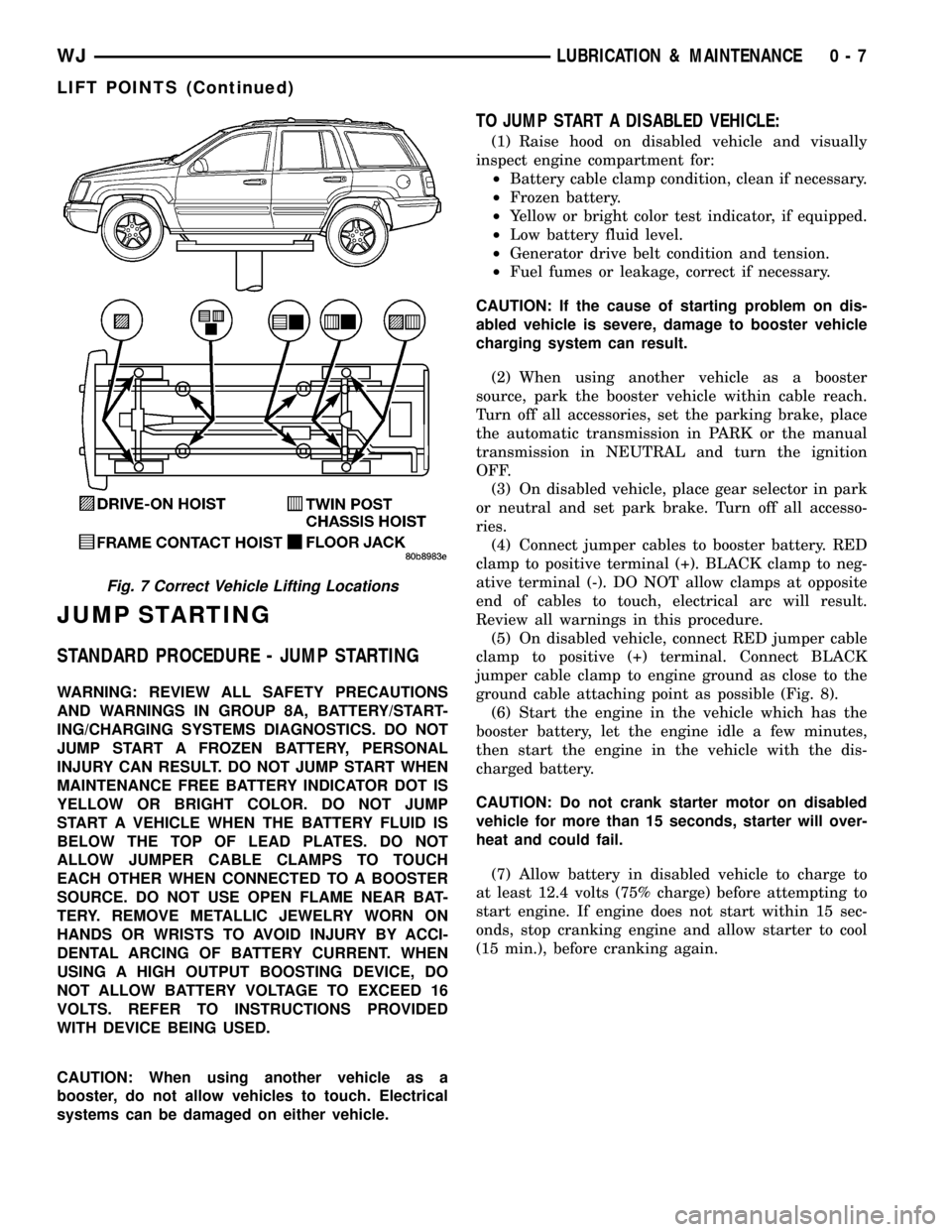
Fig. 7 Correct Vehicle Lifting Locations
WJLUBRICATION & MAINTENANCE 0 - 7
LIFT POINTS (Continued)
Page 23 of 2199

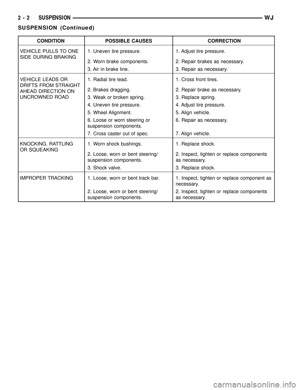
CONDITION POSSIBLE CAUSES CORRECTION
VEHICLE PULLS TO ONE
SIDE DURING BRAKING1. Uneven tire pressure. 1. Adjust tire pressure.
2. Worn brake components. 2. Repair brakes as necessary.
3. Air in brake line. 3. Repair as necessary.
VEHICLE LEADS OR
DRIFTS FROM STRAIGHT
AHEAD DIRECTION ON
UNCROWNED ROAD1. Radial tire lead. 1. Cross front tires.
2. Brakes dragging. 2. Repair brake as necessary.
3. Weak or broken spring. 3. Replace spring.
4. Uneven tire pressure. 4. Adjust tire pressure.
5. Wheel Alignment. 5. Align vehicle.
6. Loose or worn steering or
suspension components.6. Repair as necessary.
7. Cross caster out of spec. 7. Align vehicle.
KNOCKING, RATTLING
OR SQUEAKING1. Worn shock bushings. 1. Replace shock.
2. Loose, worn or bent steering/
suspension components.2. Inspect, tighten or replace components
as necessary.
3. Shock valve. 3. Replace shock.
IMPROPER TRACKING 1. Loose, worn or bent track bar. 1. Inspect, tighten or replace component as
necessary.
2. Loose, worn or bent steering/
suspension components.2. Inspect, tighten or replace components
as necessary.
2 - 2 SUSPENSIONWJ
SUSPENSION (Continued)
Page 25 of 2199

STANDARD PROCEDURE - CASTER
Before each alignment reading the vehicle should
be jounced (rear first, then front). Grasp each
bumper at the center and jounce the vehicle up and
down three times. Always release the bumper in the
down position.
To obtain an accurate alignment, a 4 wheel align-
ment machine must be used and the equipment cali-
bration verified.
The wheel caster angle is preset. This angle is not
adjustable and cannot be altered.
STANDARD PROCEDURE - TOE POSITION
Before each alignment reading the vehicle should
be jounced (rear first, then front). Grasp each
bumper at the center and jounce the vehicle up and
down three times. Always release the bumper in the
down position.To obtain an accurate alignment, a 4 wheel align-
ment machine must be used and the equipment cali-
bration verified.
NOTE: For an accurate wheel toe position adjust-
ment the engine must be engine running.
(1) Apply parking brakes.
(2) Start the engine and turn wheels both ways
before straightening the steering wheel. Center and
secure the steering wheel.
(3) Loosen the tie rod adjustment sleeve clamp
bolts (Fig. 2).
(4) Turn the sleeve to obtain the preferred positive
TOE-IN specification. Position the clamp bolts as
shown (Fig. 2) for proper clearance.
(5) Tighten the clamp bolts to 68 N´m (50 ft. lbs.).
Fig. 1 Wheel Alignment Measurements
1 - WHEEL CENTERLINE
2 - NEGATIVE CAMBER ANGLE
3 - PIVOT CENTERLINE
4 - SCRUB RADIUS
5 - TRUE VERTICAL6 - KING PIN
7 - VERTICAL
8 - POSITIVE CASTER
2 - 4 WHEEL ALIGNMENTWJ
WHEEL ALIGNMENT (Continued)
Page 30 of 2199

BUSHINGS
REMOVAL
(1) Remove the upper suspension arm from axle.
(2) Position Spacer 8279 over the axle bushing on
a 4x2 vehicle and right side on a 4x4 vehicle.
(3) Place Receiver 7932-1 over flanged end of the
bushing. (Fig. 2).
(4) Place small end of Remover/Install 7932-2
against other side of the bushing.
(5) Install bolt 7604 through remover, bushing and
receiver.
(6) Install Long Nut 7603 and tighten nut too pull
bushing out of the axle bracket.
(7) Remove nut, bolt, receiver, remover and bush-
ing.
NOTE: On 4x2 vehicle and right side of 4x4 vehicle,
leave Spacer 8279 in position for bushing installa-
tion.
INSTALLATION
(1) Place Receiver 7932-1on the other side of the
axle bracket.
(2) Position new bushing up to the axle bracket.,
and large end of Remover/Install 7932-2 against the
bushing (Fig. 3).
(3) Install bolt 7604 through receiver, bushing and
installer.
(4) Install Long Nut 7603 and tighten nut to draw
the bushing into the axle bracket.(5) Remove tools and install the upper suspension
arm.
HUB / BEARING
DESCRIPTION
The bearing used on the front hub of this vehicle is
the combined hub and bearing unit type assembly.
This unit assembly combines the front wheel mount-
ing hub (flange) and the front wheel bearing into a
one piece unit. The wheel mounting studs are the
only replaceable component of the hub/bearing
assembly.
OPERATION
The hub/bearing assembly is mounted to the steer-
ing knuckle and is retained by three mounting bolts
accessible from the back of the steering knuckle. The
hub/bearing unit is not serviceable and must be
replaced as an assembly if the bearing or the hub is
determined to be defective.
REMOVAL
(1) Raise and support the vehicle.
(2) Remove the wheel and tire assembly.
(3) Remove the brake caliper, caliper anchor, rotor
and ABS wheel speed sensor,(Refer to 5 - BRAKES/
ELECTRICAL/FRONT WHEEL SPEED SENSOR -
REMOVAL).
(4) Remove the cotter pin, nut retainer and axle
hub nut.
(5) Remove the hub bearing mounting bolts from
the back of the steering knuckle. Remove hub bear-
Fig. 2 Bushing Removal
1 - RECEIVER
2 - AXLE BRACKET
3 - BOLT
4 - REMOVER/INSTALLER
5 - LONG NUT
Fig. 3 Bushing Installation
1 - REMOVER/INSTALLER
2 - AXLE BRACKET
3 - BOLT
4 - RECEIVER
5 - LONG NUT
WJFRONT 2 - 9
Page 31 of 2199

ing (Fig. 4) from the steering knuckle and off the
axle shaft.
INSTALLATION
(1) Install the hub bearing to the knuckle.
(2) Install the hub bearing to knuckle bolts and
tighten to 102 N´m (75 ft. lbs.).
(3) Install the hub washer and nut. Tighten the
hub nut to 237 N´m (175 ft. lbs.). Install the nut
retainer and a new cotter pin.
(4) Install the brake rotor, caliper anchor, caliper
and ABS wheel speed sensor,(Refer to 5 - BRAKES/
ELECTRICAL/FRONT WHEEL SPEED SENSOR -
INSTALLATION).
(5) Install the wheel and tire assembly (Refer to 22
- TIRES/WHEELS - STANDARD PROCEDURE).
(6) Remove the support and lower the vehicle.
KNUCKLE
DESCRIPTION
The knuckle is a single casting with legs machined
for the upper and lower ball joints. The knuckle also
has machined mounting locations for the front brake
calipers and hub bearing.
OPERATION
The steering knuckle pivot between the upper and
lower ball joint. Steering linkage attached to the
knuckle allows the vehicle to be steered.
REMOVAL - STEERING KNUCKLE
Ball stud service procedures below require removal
of the hub bearing and axle shaft. Removal andinstallation of upper and lower ball studs require the
use of Tool Kit 6289.
(1) Remove hub bearing and axle shaft.
(2) Disconnect the tie-rod or drag link from the
steering knuckle arm,(Refer to 19 - STEERING/
LINKAGE/TIE ROD END - REMOVAL) .
(3) Remove the cotter pins from the upper and
lower ball studs.
(4) Remove the upper and lower ball stud nuts.
(5) Strike the steering knuckle with a brass ham-
mer to loosen knuckle from the ball studs. Remove
knuckle from ball studs (Fig. 5).
INSTALLATION
(1) Position the steering knuckle on the ball studs.
(2) Install and tighten the bottom retaining nut to
109 N´m (80 ft. lbs.) torque. Install new cotter pin.
(3) Install and tighten the top retaining nut to 101
N´m (75 ft. lbs.) torque. Install new cotter pin.
(4) Install the hub bearing and axle shaft.
(5) Connect the tie-rod or drag link end to the
steering knuckle arm.,(Refer to 19 - STEERING/
LINKAGE/TIE ROD END - INSTALLATION) .
Fig. 4 Hub Bearing & Knuckle
1 - HUB BEARING
2 - KNUCKLE
Fig. 5 Steering Knuckle Removal/Installation
1 - AXLE YOKE
2 - UPPER BALL STUD
3 - LOWER BALL STUD
4 - STEERING KNUCKLE
2 - 10 FRONTWJ
HUB / BEARING (Continued)
Page 34 of 2199

OPERATION
The coil springs control ride quality and maintain
proper ride height. The isolators provide road noise
isolation.
REMOVAL
(1) Raise and support the vehicle.
(2) Remove the wheel and tire assemblies.
(3) Position a hydraulic jack under the axle to sup-
port it.
(4) Remove shock absorbers lower mounting nuts
from the axle brackets.
(5) Remove the track bar mounting bolt from the
axle bracket.
NOTE: Make sure the lower part of the shock does
not hold tension on the brake lines at the axle tube
housing located at the lower shock mounting area.
(6) Lower the axle until the spring is free from the
upper mount and isolator (Fig. 10).
(7) Remove the spring from the vehicle.
(8) Remove and inspect the upper and lower
spring isolators.
INSTALLATION
(1) Install the upper isolator.
(2) Install the lower isolator with the isolator loca-
tor nub in the axle pad hole (Fig. 11).
(3) Position the coil spring on the axle spring pad.CAUTION: Ensure the spring is positioned on the
lower isolator with the end of the spring coil
against the isolator spring locator (Fig. 12).
(4) Raise the axle and guide the springs onto the
spring upper mounts and lower shock studs into the
axle brackets.
(5) Install the shock absorbers lower mounting
nuts.
Fig. 10 Front Coil Spring
1 - UPPER ISOLATOR
2 - COIL SPRING
3 - LOWER ISOLATOR
4 - STABILIZER LINK
Fig. 11 Lower Isolator
1 - LOCATING NUB
2 - LOWER ISOLATOR
3 - AXLE SPRING PAD
4 - LOCATING HOLE
Fig. 12 Isolator Spring Locator
1 - COIL SPRING
2 - SPRING LOCATOR
3 - LOWER ISOLATOR
WJFRONT 2 - 13
SPRING (Continued)