2003 JEEP GRAND CHEROKEE stall
[x] Cancel search: stallPage 1856 of 2199

SPECIAL TOOLS
TRANSFER CASE - NV247
Installer, Bearing - 5066
Installer, Seal - 6952-A
Installer, Bearing - 6953
Remover, Bushing - 6957
Installer, Seal - C-3995-A
Handle - C-4171
Installer, Bushing - 8145
Remover, Bearing - C-4210
Remover, Bearing - L-4454
Cup - 8148
WJTRANSFER CASE - NV247 21 - 337
TRANSFER CASE - NV247 (Continued)
Page 1857 of 2199
FLUID
STANDARD PROCEDURE - FLUID DRAIN/
REFILL
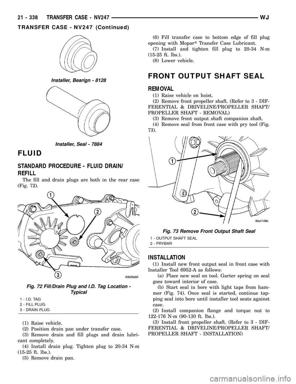
The fill and drain plugs are both in the rear case
(Fig. 72).
(1) Raise vehicle.
(2) Position drain pan under transfer case.
(3) Remove drain and fill plugs and drain lubri-
cant completely.
(4) Install drain plug. Tighten plug to 20-34 N´m
(15-25 ft. lbs.).
(5) Remove drain pan.(6) Fill transfer case to bottom edge of fill plug
opening with MopartTransfer Case Lubricant.
(7) Install and tighten fill plug to 20-34 N´m
(15-25 ft. lbs.).
(8) Lower vehicle.
FRONT OUTPUT SHAFT SEAL
REMOVAL
(1) Raise vehicle on hoist.
(2) Remove front propeller shaft. (Refer to 3 - DIF-
FERENTIAL & DRIVELINE/PROPELLER SHAFT/
PROPELLER SHAFT - REMOVAL)
(3) Remove front output shaft companion shaft.
(4) Remove seal from front case with pry tool (Fig.
73).
INSTALLATION
(1) Install new front output seal in front case with
Installer Tool 6952-A as follows:
(a) Place new seal on tool. Garter spring on seal
goes toward interior of case.
(b) Start seal in bore with light taps from ham-
mer (Fig. 74). Once seal is started, continue tap-
ping seal into bore until installer tool seats against
case.
(2) Install companion flange and torque nut to
122-176 N´m (90-130 ft. lbs.).
(3) Install front propeller shaft. (Refer to 3 - DIF-
FERENTIAL & DRIVELINE/PROPELLER SHAFT/
PROPELLER SHAFT - INSTALLATION)
Installer, Bearign - 8128
Installer, Seal - 7884
Fig. 72 Fill/Drain Plug and I.D. Tag Location -
Typical
1 - I.D. TAG
2 - FILL PLUG
3 - DRAIN PLUG
Fig. 73 Remove Front Output Shaft Seal
1 - OUTPUT SHAFT SEAL
2 - PRYBAR
21 - 338 TRANSFER CASE - NV247WJ
TRANSFER CASE - NV247 (Continued)
Page 1858 of 2199
REAR RETAINER BUSHING
AND SEAL
REMOVAL
(1) Raise vehicle on hoist.
(2) Remove rear propeller shaft. (Refer to 3 - DIF-
FERENTIAL & DRIVELINE/PROPELLER SHAFT/
PROPELLER SHAFT - REMOVAL)
(3) Using a suitable pry tool or slide-hammer
mounted screw, remove the rear retainer seal.
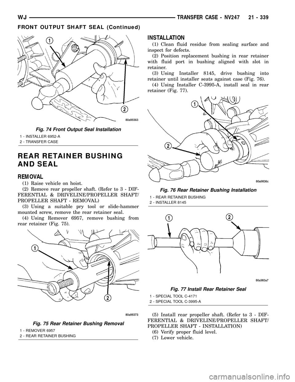
(4) Using Remover 6957, remove bushing from
rear retainer (Fig. 75).
INSTALLATION
(1) Clean fluid residue from sealing surface and
inspect for defects.
(2) Position replacement bushing in rear retainer
with fluid port in bushing aligned with slot in
retainer.
(3) Using Installer 8145, drive bushing into
retainer until installer seats against case (Fig. 76).
(4) Using Installer C-3995-A, install seal in rear
retainer (Fig. 77).
(5) Install rear propeller shaft. (Refer to 3 - DIF-
FERENTIAL & DRIVELINE/PROPELLER SHAFT/
PROPELLER SHAFT - INSTALLATION)
(6) Verify proper fluid level.
(7) Lower vehicle.
Fig. 74 Front Output Seal Installation
1 - INSTALLER 6952-A
2 - TRANSFER CASE
Fig. 75 Rear Retainer Bushing Removal
1 - REMOVER 6957
2 - REAR RETAINER BUSHING
Fig. 76 Rear Retainer Bushing Installation
1 - REAR RETAINER BUSHING
2 - INSTALLER 8145
Fig. 77 Install Rear Retainer Seal
1 - SPECIAL TOOL C-4171
2 - SPECIAL TOOL C-3995-A
WJTRANSFER CASE - NV247 21 - 339
FRONT OUTPUT SHAFT SEAL (Continued)
Page 1859 of 2199
SHIFT CABLE
REMOVAL
(1) Shift transfer case into NEUTRAL.
(2) Raise vehicle.
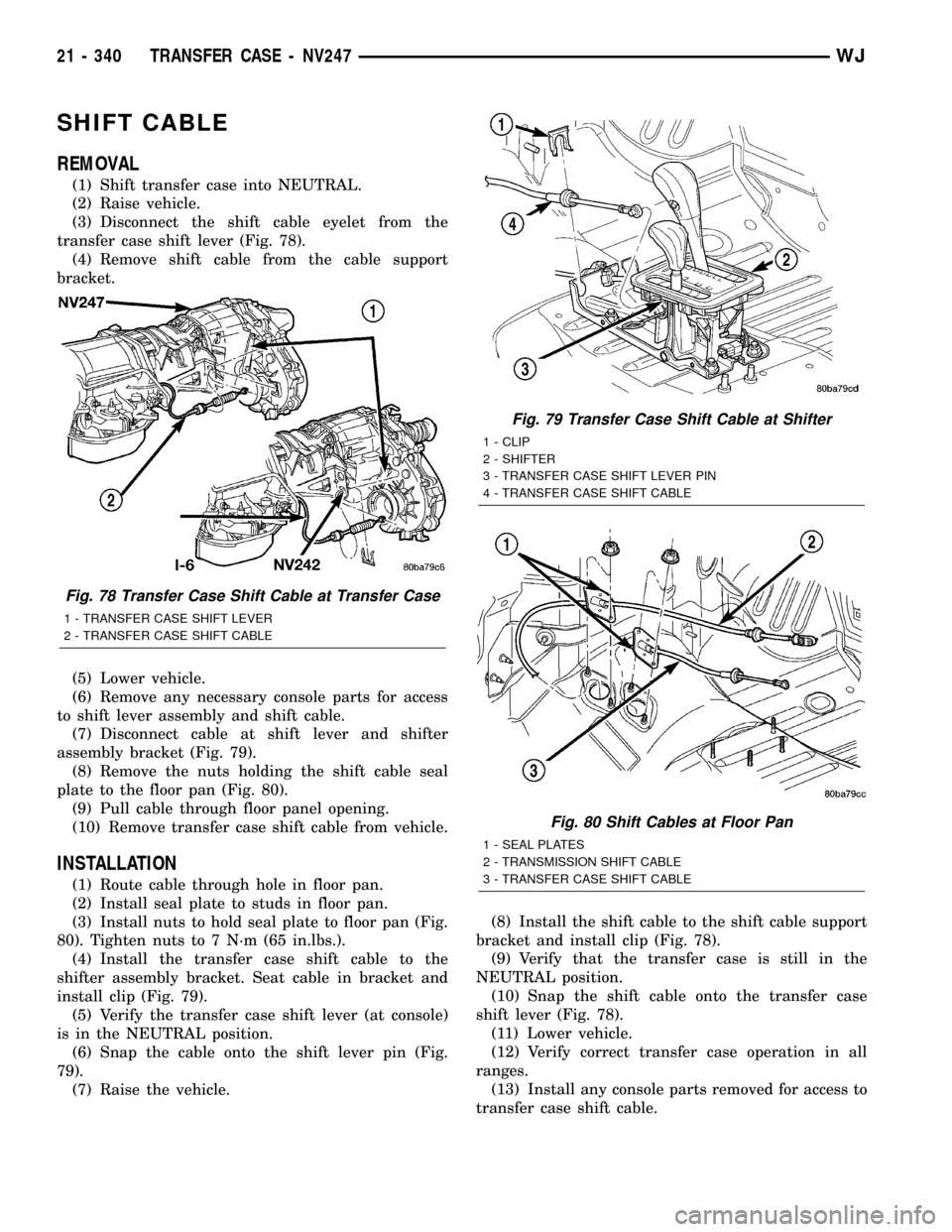
(3) Disconnect the shift cable eyelet from the
transfer case shift lever (Fig. 78).
(4) Remove shift cable from the cable support
bracket.
(5) Lower vehicle.
(6) Remove any necessary console parts for access
to shift lever assembly and shift cable.
(7) Disconnect cable at shift lever and shifter
assembly bracket (Fig. 79).
(8) Remove the nuts holding the shift cable seal
plate to the floor pan (Fig. 80).
(9) Pull cable through floor panel opening.
(10) Remove transfer case shift cable from vehicle.
INSTALLATION
(1) Route cable through hole in floor pan.
(2) Install seal plate to studs in floor pan.
(3) Install nuts to hold seal plate to floor pan (Fig.
80). Tighten nuts to 7 N´m (65 in.lbs.).
(4) Install the transfer case shift cable to the
shifter assembly bracket. Seat cable in bracket and
install clip (Fig. 79).
(5) Verify the transfer case shift lever (at console)
is in the NEUTRAL position.
(6) Snap the cable onto the shift lever pin (Fig.
79).
(7) Raise the vehicle.(8) Install the shift cable to the shift cable support
bracket and install clip (Fig. 78).
(9) Verify that the transfer case is still in the
NEUTRAL position.
(10) Snap the shift cable onto the transfer case
shift lever (Fig. 78).
(11) Lower vehicle.
(12) Verify correct transfer case operation in all
ranges.
(13) Install any console parts removed for access to
transfer case shift cable.
Fig. 78 Transfer Case Shift Cable at Transfer Case
1 - TRANSFER CASE SHIFT LEVER
2 - TRANSFER CASE SHIFT CABLE
Fig. 79 Transfer Case Shift Cable at Shifter
1 - CLIP
2 - SHIFTER
3 - TRANSFER CASE SHIFT LEVER PIN
4 - TRANSFER CASE SHIFT CABLE
Fig. 80 Shift Cables at Floor Pan
1 - SEAL PLATES
2 - TRANSMISSION SHIFT CABLE
3 - TRANSFER CASE SHIFT CABLE
21 - 340 TRANSFER CASE - NV247WJ
Page 1860 of 2199
TIRES/WHEELS
TABLE OF CONTENTS
page page
TIRES/WHEELS
DIAGNOSIS AND TESTING - TIRE AND
WHEEL RUNOUT......................1
STANDARD PROCEDURE
STANDARD PROCEDURE - TIRE AND
WHEEL BALANCE......................2
STANDARD PROCEDURE - MATCH
MOUNTING...........................4
STANDARD PROCEDURE - TIRE ROTATION . 5
STANDARD PROCEDURE - WHEEL
INSTALLATION........................5
TIRES
DESCRIPTION
DESCRIPTION - TIRES..................6
DESCRIPTION - RADIAL±PLY TIRES.......6
DESCRIPTION - TIRE INFLATION
PRESSURES..........................6
DESCRIPTION - TIRE PRESSURE FOR
HIGH SPEED..........................7
DESCRIPTION - REPLACEMENT TIRES.....7
DIAGNOSIS AND TESTING
DIAGNOSIS AND TESTING - PRESSURE
GAUGES.............................8
DIAGNOSIS AND TESTING - TREAD WEAR
INDICATORS..........................8
DIAGNOSIS AND TESTING - TIRE WEAR
PATTERNS...........................8
DIAGNOSIS AND TESTING - TIRE NOISE
OR VIBRATION........................8STANDARD PROCEDURE - REPAIRING
LEAKS...............................8
CLEANING.............................9
SPECIFICATIONS
TIRES...............................9
SPECIFICATIONS -.....................9
SPARE TIRE
DESCRIPTION - SPARE / TEMPORARY TIRE . . 10
WHEELS
DESCRIPTION.........................10
DIAGNOSIS AND TESTING - WHEEL
INSPECTION.........................10
STANDARD PROCEDURE - WHEEL
REPLACEMENT.......................10
SPECIFICATIONS
TORQUE CHART......................11
STUDS
REMOVAL.............................11
INSTALLATION.........................11
TIRE PRESSURE MONITORING
DESCRIPTION.........................12
OPERATION...........................12
DIAGNOSIS AND TESTING - TIRE PRESSURE
MONITORING SYSTEM.................12
SENSOR
REMOVAL - TIRE PRESSURE SENSOR/
TRANSMITTER.......................12
INSTALLATION - TIRE PRESSURE SENSOR/
TRANSMITTER.......................13
TIRES/WHEELS
DIAGNOSIS AND TESTING - TIRE AND WHEEL
RUNOUT
Radial runout is the difference between the high
and low points on the tire or wheel (Fig. 1).
Lateral runout is thewobbleof the tire or wheel.
Radial runout of more than 1.5 mm (.060 inch)
measured at the center line of the tread may cause
the vehicle to shake.
Lateral runout of more than 2.0 mm (.080 inch)
measured near the shoulder of the tire may cause the
vehicle to shake.
Sometimes radial runout can be reduced. Relocate
the wheel and tire assembly on the mounting studs
(See Method 1). If this does not reduce runout to an
acceptable level, the tire can be rotated on the wheel.
(See Method 2).
METHOD 1 (RELOCATE WHEEL ON HUB)
(1) Drive vehicle a short distance to eliminate tire
flat spotting from a parked position.
(2) Check wheel bearings and adjust if adjustable
or replace if necessary.
(3) Check the wheel mounting surface.
(4) Relocate wheel on the mounting, two studs
over from the original position.
(5) Tighten wheel nuts until all are properly
torqued, to eliminate brake distortion.
(6) Check radial runout. If still excessive, mark
tire sidewall, wheel, and stud at point of maximum
runout and proceed to Method 2.
METHOD 2 (RELOCATE TIRE ON WHEEL)
NOTE: Rotating the tire on wheel is particularly
effective when there is runout in both tire and
wheel.
WJTIRES/WHEELS 22 - 1
Page 1864 of 2199
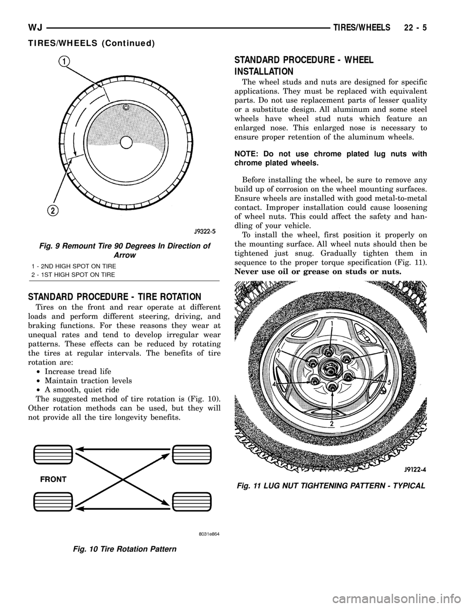
STANDARD PROCEDURE - TIRE ROTATION
Tires on the front and rear operate at different
loads and perform different steering, driving, and
braking functions. For these reasons they wear at
unequal rates and tend to develop irregular wear
patterns. These effects can be reduced by rotating
the tires at regular intervals. The benefits of tire
rotation are:
²Increase tread life
²Maintain traction levels
²A smooth, quiet ride
The suggested method of tire rotation is (Fig. 10).
Other rotation methods can be used, but they will
not provide all the tire longevity benefits.
STANDARD PROCEDURE - WHEEL
INSTALLATION
The wheel studs and nuts are designed for specific
applications. They must be replaced with equivalent
parts. Do not use replacement parts of lesser quality
or a substitute design. All aluminum and some steel
wheels have wheel stud nuts which feature an
enlarged nose. This enlarged nose is necessary to
ensure proper retention of the aluminum wheels.
NOTE: Do not use chrome plated lug nuts with
chrome plated wheels.
Before installing the wheel, be sure to remove any
build up of corrosion on the wheel mounting surfaces.
Ensure wheels are installed with good metal-to-metal
contact. Improper installation could cause loosening
of wheel nuts. This could affect the safety and han-
dling of your vehicle.
To install the wheel, first position it properly on
the mounting surface. All wheel nuts should then be
tightened just snug. Gradually tighten them in
sequence to the proper torque specification (Fig. 11).
Never use oil or grease on studs or nuts.
Fig. 9 Remount Tire 90 Degrees In Direction of
Arrow
1 - 2ND HIGH SPOT ON TIRE
2 - 1ST HIGH SPOT ON TIRE
Fig. 10 Tire Rotation Pattern
Fig. 11 LUG NUT TIGHTENING PATTERN - TYPICAL
WJTIRES/WHEELS 22 - 5
TIRES/WHEELS (Continued)
Page 1867 of 2199

DIAGNOSIS AND TESTING
DIAGNOSIS AND TESTING - PRESSURE
GAUGES
A quality air pressure gauge is recommended to
check tire pressure. After checking the air pressure,
replace valve cap finger tight.
DIAGNOSIS AND TESTING - TREAD WEAR
INDICATORS
Tread wear indicators are molded into the bottom
of the tread grooves. When tread depth is 1.6 mm
(1/16 in.), the tread wear indicators will appear as a
13 mm (1/2 in.) band (Fig. 15).
Tire replacement is necessary when indicators
appear in two or more grooves or if localized balding
occurs.
DIAGNOSIS AND TESTING - TIRE WEAR
PATTERNS
Under inflation will cause wear on the shoulders of
tire. Over inflation will cause wear at the center of
tire.
Excessive camber causes the tire to run at an
angle to the road. One side of tread is then worn
more than the other (Fig. 16).
Excessive toe-in or toe-out causes wear on the
tread edges and a feathered effect across the tread
(Fig. 16).
DIAGNOSIS AND TESTING - TIRE NOISE OR
VIBRATION
Radial-ply tires are sensitive to force impulses
caused by improper mounting, vibration, wheel
defects, or possibly tire imbalance.
To find out if tires are causing the noise or vibra-
tion, drive the vehicle over a smooth road at varying
speeds. Note the noise level during acceleration and
deceleration. The engine, differential and exhaust
noises will change as speed varies, while the tire
noise will usually remain constant.
STANDARD PROCEDURE - REPAIRING LEAKS
For proper repairing, a radial tire must be removed
from the wheel. Repairs should only be made if the
defect, or puncture, is in the tread area (Fig. 17). The
tire should be replaced if the puncture is located in
the sidewall.
Deflate tire completely before removing the tire
from the wheel. Use lubrication such as a mild soap
solution when dismounting or mounting tire. Use
tools free of burrs or sharp edges which could dam-
age the tire or wheel rim.
Before mounting tire on wheel, make sure all rust
is removed from the rim bead and repaint if neces-
sary.
Install wheel on vehicle, and tighten to proper
torque specification (Refer to 22 - TIRES/WHEELS/
WHEELS - SPECIFICATIONS).
Fig. 15 Tread Wear Indicators
1 - TREAD ACCEPTABLE
2 - TREAD UNACCEPTABLE
3 - WEAR INDICATOR
22 - 8 TIRES/WHEELSWJ
Page 1869 of 2199

SPARE TIRE
DESCRIPTION - SPARE / TEMPORARY TIRE
The temporary spare tire is designed for emer-
gency use only. The original tire should be repaired
or replaced at the first opportunity, then reinstalled.
Do not exceed speeds of 50 M.P.H. when using the
temporary spare tire. Refer to Owner's Manual for
complete details.
WHEELS
DESCRIPTION
The rim size is on the vehicle safety certification
label located on the drivers door shut face. The size
of the rim is determined by the drivetrain package.
Original equipment wheels/rims are designed for
operation up to the specified maximum vehicle capac-
ity.
All models use stamped steel, cast aluminum or
forged aluminum wheels. Every wheel has raised sec-
tions between the rim flanges and rim drop well
called safety humps (Fig. 18) .
Initial inflation of the tire forces the bead over
these raised sections. In case of rapid loss of air pres-
sure, the raised sections help hold the tire on the
wheel.
The wheel studs and nuts are designed for specific
applications. All aluminum and some steel wheels
have wheel stud nuts with an enlarged nose. This
enlarged nose is necessary to ensure proper retentionof the wheels. Do not use replacement studs or nuts
with a different design or lesser quality.
DIAGNOSIS AND TESTING - WHEEL
INSPECTION
Inspect wheels for:
²Excessive run out
²Dents or cracks
²Damaged wheel lug nut holes
²Air Leaks from any area or surface of the rim
NOTE: Do not attempt to repair a wheel by hammer-
ing, heating or welding.
If a wheel is damaged an original equipment
replacement wheel should be used. When obtaining
replacement wheels, they should be equivalent in
load carrying capacity. The diameter, width, offset,
pilot hole and bolt circle of the wheel should be the
same as the original wheel.
WARNING: FAILURE TO USE EQUIVALENT
REPLACEMENT WHEELS MAY ADVERSELY
AFFECT THE SAFETY AND HANDLING OF THE
VEHICLE. USED WHEELS ARE NOT RECOM-
MENDED. THE SERVICE HISTORY OF THE WHEEL
MAY HAVE INCLUDED SEVERE TREATMENT OR
VERY HIGH MILEAGE. THE RIM COULD FAIL WITH-
OUT WARNING.
STANDARD PROCEDURE - WHEEL
REPLACEMENT
The wheel studs and nuts are designed for specific
applications. They must be replaced with equivalent
parts. Do not use replacement parts of lesser quality
or a substitute design. All aluminum and some steel
wheels have wheel stud nuts which feature an
enlarged nose. This enlarged nose is necessary to
ensure proper retention of the aluminum wheels.
NOTE: Do not use chrome plated lug nuts with
chrome plated wheels.
Before installing the wheel, be sure to remove any
build up of corrosion on the wheel mounting surfaces.
Ensure wheels are installed with good metal-to-metal
contact. Improper installation could cause loosening
of wheel nuts. This could affect the safety and han-
dling of your vehicle.
To install the wheel, first position it properly on
the mounting surface. All wheel nuts should then be
tightened just snug. Gradually tighten them in
sequence to the proper torque specification.Never
use oil or grease on studs or nuts.
Wheels must be replaced if they have:
²Excessive runout
Fig. 18 Safety Rim
1 - FLANGE
2 - RIDGE
3 - WELL
22 - 10 TIRES/WHEELSWJ