2003 JEEP GRAND CHEROKEE fuel pump
[x] Cancel search: fuel pumpPage 1647 of 2199

NOTE: Be sure that as the cable is pulled forward
and centered on the throttle lever stud, the cable
housing moves smoothly with the cable. Due to the
angle at which the cable housing enters the spring
housing, the cable housing may bind slightly and
create an incorrect adjustment.
(8) Reconnect the T.V. cable (B) to the throttle
bellcrank lever (C).
(9) Check cable adjustment. Verify transmission
throttle lever and lever on throttle body move simul-
taneously.
TORQUE CONVERTER
DESCRIPTION
The torque converter (Fig. 245) is a hydraulic
device that couples the engine crankshaft to the
transmission. The torque converter consists of an
outer shell with an internal turbine, a stator, an
overrunning clutch, an impeller and an electronically
applied converter clutch. The converter clutch pro-
vides reduced engine speed and greater fuel economy
when engaged. Clutch engagement also provides
reduced transmission fluid temperatures. The torque
converter hub drives the transmission oil (fluid)
pump.
The torque converter is a sealed, welded unit that
is not repairable and is serviced as an assembly.
CAUTION: The torque converter must be replaced if
a transmission failure resulted in large amounts of
metal or fiber contamination in the fluid. If the fluid
is contaminated, flush the all transmission fluid
cooler(s) and lines.
Fig. 244 Throttle Valve Cable at Throttle Linkage
1 - THROTTLE LINKAGE
2 - THROTTLE VALVE CABLE LOCKING CLIP
3 - THROTTLE VALVE CABLE
Fig. 245 Torque Converter Assembly
1 - TURBINE
2 - IMPELLER
3 - HUB
4-STATOR
5 - FRONT COVER
6 - CONVERTER CLUTCH DISC
7 - DRIVE PLATE
21 - 128 AUTOMATIC TRANSMISSION - 42REWJ
THROTTLE VALVE CABLE (Continued)
Page 1697 of 2199

INSTALLATION........................253
OUTPUT SPEED SENSOR
DESCRIPTION........................254
OPERATION..........................254
REMOVAL............................254
INSTALLATION........................254
OVERDRIVE SWITCH
DESCRIPTION........................254
OPERATION..........................254
PARK LOCK CABLE
REMOVAL............................255
INSTALLATION........................255
PISTONS
DESCRIPTION........................256
OPERATION..........................256
PLANETARY GEARTRAIN
DESCRIPTION........................258
OPERATION..........................260
DISASSEMBLY........................260
CLEANING...........................260
INSPECTION.........................260
ASSEMBLY...........................261
SHIFT MECHANISM
DESCRIPTION........................261
OPERATION..........................261
REMOVAL............................261
INSTALLATION........................263
SOLENOID SWITCH VALVE
DESCRIPTION........................263
OPERATION..........................263
SOLENOIDS
DESCRIPTION........................263OPERATION..........................264
TORQUE CONVERTER
DESCRIPTION........................264
OPERATION..........................268
REMOVAL............................269
INSTALLATION........................269
TRANSMISSION CONTROL RELAY
DESCRIPTION........................270
OPERATION..........................270
TRANSMISSION RANGE SENSOR
DESCRIPTION........................270
OPERATION..........................270
TRANSMISSION SOLENOID/TRS ASSEMBLY
DESCRIPTION........................271
OPERATION..........................271
REMOVAL............................272
INSTALLATION........................272
TRANSMISSION TEMPERATURE SENSOR
DESCRIPTION........................272
OPERATION..........................272
VALVE BODY
DESCRIPTION........................273
OPERATION..........................273
REMOVAL............................274
DISASSEMBLY........................275
CLEANING...........................277
INSPECTION.........................277
ASSEMBLY...........................278
INSTALLATION........................279
AUTOMATIC TRANSMISSION -
545RFE
DESCRIPTION
The 545RFE automatic transmission is a sophisti-
cated, multi-range, electronically controlled transmis-
sion which combines optimized gear ratios for
responsive performance, state of the art efficiency
features and low NVH. Other features include driver
adaptive shifting and three planetary gear sets to
provide wide ratio capability with precise ratio steps
for optimum driveability. The three planetary gear
sets also make available a unique alternate second
gear ratio. The primary 2nd gear ratio fits between
1st and 3rd gears for normal through-gear accelera-
tions. The alternate second gear ratio (2prime) allows
smoother 4-2 kickdowns at high speeds to provide
2nd gear passing performance over a wider highway
cruising range. An additional overdrive ratio (0.67:1)
is also provided for greater fuel economy and less
NVH at highway speeds.The hydraulic portion of the transmission consists
of the transmission fluid, fluid passages, hydraulic
valves, and various line pressure control components.
The primary mechanical components of the trans-
mission consist of the following:
²Three multiple disc input clutches
²Three multiple disc holding clutches
²Five hydraulic accumulators
²Three planetary gear sets
²Dual Stage Hydraulic oil pump
²Valve body
²Solenoid pack
The TCM is the ªheartº or ªbrainº of the electronic
control system and relies on information from vari-
ous direct and indirect inputs (sensors, switches, etc.)
to determine driver demand and vehicle operating
conditions. With this information, the TCM can cal-
culate and perform timely and quality shifts through
various output or control devices (solenoid pack,
transmission control relay, etc.).
21 - 178 AUTOMATIC TRANSMISSION - 545RFEWJ
Page 1783 of 2199

A solenoid can also be described by the method by
which it is controlled. Some of the possibilities
include variable force, pulse-width modulated, con-
stant ON, or duty cycle. The variable force and pulse-
width modulated versions utilize similar methods to
control the current flow through the solenoid to posi-
tion the solenoid plunger at a desired position some-
where between full ON and full OFF. The constant
ON and duty cycled versions control the voltage
across the solenoid to allow either full flow or no flow
through the solenoid's valve.
OPERATION
When an electrical current is applied to the sole-
noid coil, a magnetic field is created which produces
an attraction to the plunger, causing the plunger to
move and work against the spring pressure and the
load applied by the fluid the valve is controlling. The
plunger is normally directly attached to the valve
which it is to operate. When the current is removed
from the coil, the attraction is removed and the
plunger will return to its original position due to
spring pressure.
The plunger is made of a conductive material and
accomplishes this movement by providing a path for
the magnetic field to flow. By keeping the air gap
between the plunger and the coil to the minimum
necessary to allow free movement of the plunger, the
magnetic field is maximized.
TORQUE CONVERTER
DESCRIPTION
The torque converter (Fig. 109) is a hydraulic
device that couples the engine crankshaft to the
transmission. The torque converter consists of an
outer shell with an internal turbine, a stator, an
overrunning clutch, an impeller and an electronically
applied converter clutch. The converter clutch pro-vides reduced engine speed and greater fuel economy
when engaged. Clutch engagement also provides
reduced transmission fluid temperatures. The con-
verter clutch engages in third gear. The torque con-
verter hub drives the transmission oil (fluid) pump
and contains an o-ring seal to better control oil flow.
The torque converter is a sealed, welded unit that
is not repairable and is serviced as an assembly.
CAUTION: The torque converter must be replaced if
a transmission failure resulted in large amounts of
metal or fiber contamination in the fluid. If the fluid
is contaminated, flush the fluid cooler and lines.
Fig. 109 Torque Converter Assembly
1 - TURBINE ASSEMBLY
2-STATOR
3 - CONVERTER HUB
4 - O-RING
5 - IMPELLER ASSEMBLY
6 - CONVERTER CLUTCH PISTON
7 - TURBINE HUB
21 - 264 AUTOMATIC TRANSMISSION - 545RFEWJ
SOLENOIDS (Continued)
Page 2159 of 2199
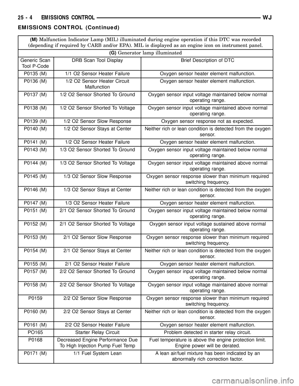
(M)Malfunction Indicator Lamp (MIL) illuminated during engine operation if this DTC was recorded
(depending if required by CARB and/or EPA). MIL is displayed as an engine icon on instrument panel.
(G)Generator lamp illuminated
Generic Scan
Tool P-CodeDRB Scan Tool Display Brief Description of DTC
P0135 (M) 1/1 O2 Sensor Heater Failure Oxygen sensor heater element malfunction.
P0136 (M) 1/2 O2 Sensor Heater Circuit
MalfunctionOxygen sensor heater element malfunction.
P0137 (M) 1/2 O2 Sensor Shorted To Ground Oxygen sensor input voltage maintained below normal
operating range.
P0138 (M) 1/2 O2 Sensor Shorted To Voltage Oxygen sensor input voltage maintained above normal
operating range.
P0139 (M) 1/2 O2 Sensor Slow Response Oxygen sensor response not as expected.
P0140 (M) 1/2 O2 Sensor Stays at Center Neither rich or lean condition is detected from the oxygen
sensor.
P0141 (M) 1/2 O2 Sensor Heater Failure Oxygen sensor heater element malfunction.
P0143 (M) 1/3 O2 Sensor Shorted To Ground Oxygen sensor input voltage maintained below normal
operating range.
P0144 (M) 1/3 O2 Sensor Shorted To Voltage Oxygen sensor input voltage maintained above normal
operating range.
P0145 (M) 1/3 O2 Sensor Slow Response Oxygen sensor response slower than minimum required
switching frequency.
P0146 (M) 1/3 O2 Sensor Stays at Center Neither rich or lean condition is detected from the oxygen
sensor.
P0147 (M) 1/3 O2 Sensor Heater Failure Oxygen sensor heater element malfunction.
P0151 (M) 2/1 O2 Sensor Shorted To Ground Oxygen sensor input voltage maintained below normal
operating range.
P0152 (M) 2/1 O2 Sensor Shorted To Voltage Oxygen sensor input voltage sustained above normal
operating range.
P0153 (M) 2/1 O2 Sensor Slow Response Oxygen sensor response slower than minimum required
switching frequency.
P0154 (M) 2/1 O2 Sensor Stays at Center Neither rich or lean condition is detected from the oxygen
sensor.
P0155 (M) 2/1 O2 Sensor Heater Failure Oxygen sensor heater element malfunction.
P0157 (M) 2/2 O2 Sensor Shorted To Ground Oxygen sensor input voltage maintained below normal
operating range.
P0158 (M) 2/2 O2 Sensor Shorted To Voltage Oxygen sensor input voltage maintained above normal
operating range.
P0159 2/2 O2 Sensor Slow Response Oxygen sensor response slower than minimum required
switching frequency.
P0160 (M) 2/2 O2 Sensor Stays at Center Neither rich or lean condition is detected from the oxygen
sensor.
P0161 (M) 2/2 O2 Sensor Heater Failure Oxygen sensor heater element malfunction.
PO165 Starter Relay Circuit Problem detected in starter relay circuit.
P0168 Decreased Engine Performance Due
To High Injection Pump Fuel TempFuel temperature is above the engine protection limit.
Engine power will be derated.
P0171 (M) 1/1 Fuel System Lean A lean air/fuel mixture has been indicated by an
abnormally rich correction factor.
25 - 4 EMISSIONS CONTROLWJ
EMISSIONS CONTROL (Continued)
Page 2160 of 2199
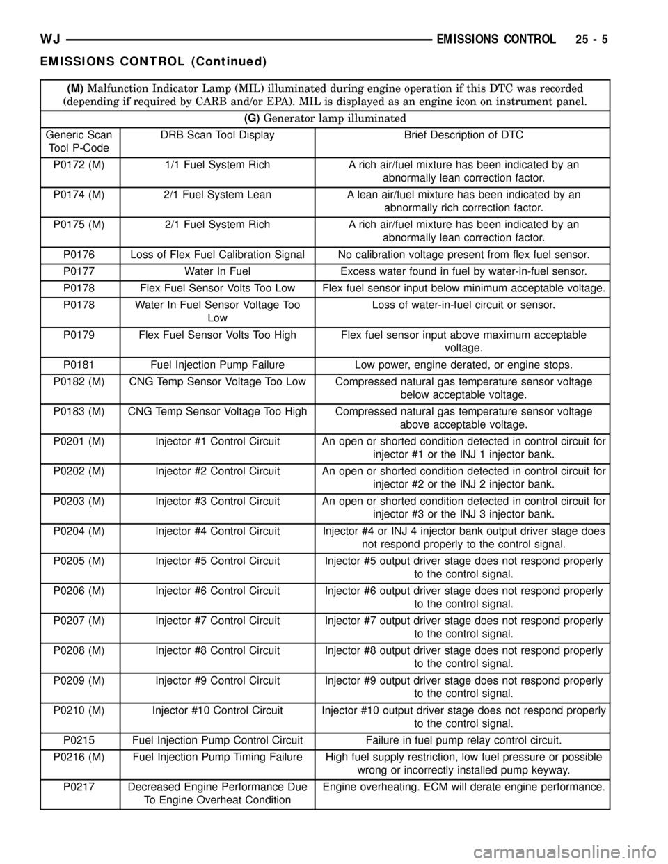
(M)Malfunction Indicator Lamp (MIL) illuminated during engine operation if this DTC was recorded
(depending if required by CARB and/or EPA). MIL is displayed as an engine icon on instrument panel.
(G)Generator lamp illuminated
Generic Scan
Tool P-CodeDRB Scan Tool Display Brief Description of DTC
P0172 (M) 1/1 Fuel System Rich A rich air/fuel mixture has been indicated by an
abnormally lean correction factor.
P0174 (M) 2/1 Fuel System Lean A lean air/fuel mixture has been indicated by an
abnormally rich correction factor.
P0175 (M) 2/1 Fuel System Rich A rich air/fuel mixture has been indicated by an
abnormally lean correction factor.
P0176 Loss of Flex Fuel Calibration Signal No calibration voltage present from flex fuel sensor.
P0177 Water In Fuel Excess water found in fuel by water-in-fuel sensor.
P0178 Flex Fuel Sensor Volts Too Low Flex fuel sensor input below minimum acceptable voltage.
P0178 Water In Fuel Sensor Voltage Too
LowLoss of water-in-fuel circuit or sensor.
P0179 Flex Fuel Sensor Volts Too High Flex fuel sensor input above maximum acceptable
voltage.
P0181 Fuel Injection Pump Failure Low power, engine derated, or engine stops.
P0182 (M) CNG Temp Sensor Voltage Too Low Compressed natural gas temperature sensor voltage
below acceptable voltage.
P0183 (M) CNG Temp Sensor Voltage Too High Compressed natural gas temperature sensor voltage
above acceptable voltage.
P0201 (M) Injector #1 Control Circuit An open or shorted condition detected in control circuit for
injector #1 or the INJ 1 injector bank.
P0202 (M) Injector #2 Control Circuit An open or shorted condition detected in control circuit for
injector #2 or the INJ 2 injector bank.
P0203 (M) Injector #3 Control Circuit An open or shorted condition detected in control circuit for
injector #3 or the INJ 3 injector bank.
P0204 (M) Injector #4 Control Circuit Injector #4 or INJ 4 injector bank output driver stage does
not respond properly to the control signal.
P0205 (M) Injector #5 Control Circuit Injector #5 output driver stage does not respond properly
to the control signal.
P0206 (M) Injector #6 Control Circuit Injector #6 output driver stage does not respond properly
to the control signal.
P0207 (M) Injector #7 Control Circuit Injector #7 output driver stage does not respond properly
to the control signal.
P0208 (M) Injector #8 Control Circuit Injector #8 output driver stage does not respond properly
to the control signal.
P0209 (M) Injector #9 Control Circuit Injector #9 output driver stage does not respond properly
to the control signal.
P0210 (M) Injector #10 Control Circuit Injector #10 output driver stage does not respond properly
to the control signal.
P0215 Fuel Injection Pump Control Circuit Failure in fuel pump relay control circuit.
P0216 (M) Fuel Injection Pump Timing Failure High fuel supply restriction, low fuel pressure or possible
wrong or incorrectly installed pump keyway.
P0217 Decreased Engine Performance Due
To Engine Overheat ConditionEngine overheating. ECM will derate engine performance.
WJEMISSIONS CONTROL 25 - 5
EMISSIONS CONTROL (Continued)
Page 2161 of 2199
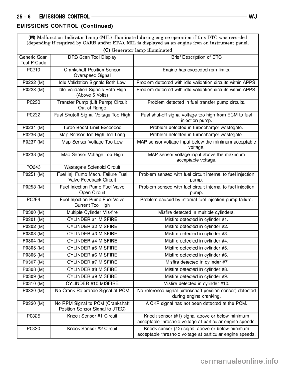
(M)Malfunction Indicator Lamp (MIL) illuminated during engine operation if this DTC was recorded
(depending if required by CARB and/or EPA). MIL is displayed as an engine icon on instrument panel.
(G)Generator lamp illuminated
Generic Scan
Tool P-CodeDRB Scan Tool Display Brief Description of DTC
P0219 Crankshaft Position Sensor
Overspeed SignalEngine has exceeded rpm limits.
P0222 (M) Idle Validation Signals Both Low Problem detected with idle validation circuits within APPS.
P0223 (M) Idle Validation Signals Both High
(Above 5 Volts)Problem detected with idle validation circuits within APPS.
P0230 Transfer Pump (Lift Pump) Circuit
Out of RangeProblem detected in fuel transfer pump circuits.
P0232 Fuel Shutoff Signal Voltage Too High Fuel shut-off signal voltage too high from ECM to fuel
injection pump.
P0234 (M) Turbo Boost Limit Exceeded Problem detected in turbocharger wastegate.
P0236 (M) Map Sensor Too High Too Long Problem detected in turbocharger wastegate.
P0237 (M) Map Sensor Voltage Too Low MAP sensor voltage input below the minimum acceptable
voltage.
P0238 (M) Map Sensor Voltage Too High MAP sensor voltage input above the maximum
acceptable voltage.
PO243 Wastegate Solenoid Circuit
P0251 (M) Fuel Inj. Pump Mech. Failure Fuel
Valve Feedback CircuitProblem sensed with fuel circuit internal to fuel injection
pump.
P0253 (M) Fuel Injection Pump Fuel Valve
Open CircuitProblem sensed with fuel circuit internal to fuel injection
pump.
P0254 Fuel Injection Pump Fuel Valve
Current Too HighProblem caused by internal fuel injection pump failure.
P0300 (M) Multiple Cylinder Mis-fire Misfire detected in multiple cylinders.
P0301 (M) CYLINDER #1 MISFIRE Misfire detected in cylinder #1.
P0302 (M) CYLINDER #2 MISFIRE Misfire detected in cylinder #2.
P0303 (M) CYLINDER #3 MISFIRE Misfire detected in cylinder #3.
P0304 (M) CYLINDER #4 MISFIRE Misfire detected in cylinder #4.
P0305 (M) CYLINDER #5 MISFIRE Misfire detected in cylinder #5.
P0306 (M) CYLINDER #6 MISFIRE Misfire detected in cylinder #6.
P0307 (M) CYLINDER #7 MISFIRE Misfire detected in cylinder #7
P0308 (M) CYLINDER #8 MISFIRE Misfire detected in cylinder #8.
P0309 (M) CYLINDER #9 MISFIRE Misfire detected in cylinder #9.
P0310 (M) CYLINDER #10 MISFIRE Misfire detected in cylinder #10.
P0320 (M) No Crank Referance Signal at PCM No reference signal (crankshaft position sensor) detected
during engine cranking.
P0320 (M) No RPM Signal to PCM (Crankshaft
Position Sensor Signal to JTEC)A CKP signal has not been detected at the PCM.
P0325 Knock Sensor #1 Circuit Knock sensor (#1) signal above or below minimum
acceptable threshold voltage at particular engine speeds.
P0330 Knock Sensor #2 Circuit Knock sensor (#2) signal above or below minimum
acceptable threshold voltage at particular engine speeds.
25 - 6 EMISSIONS CONTROLWJ
EMISSIONS CONTROL (Continued)
Page 2162 of 2199
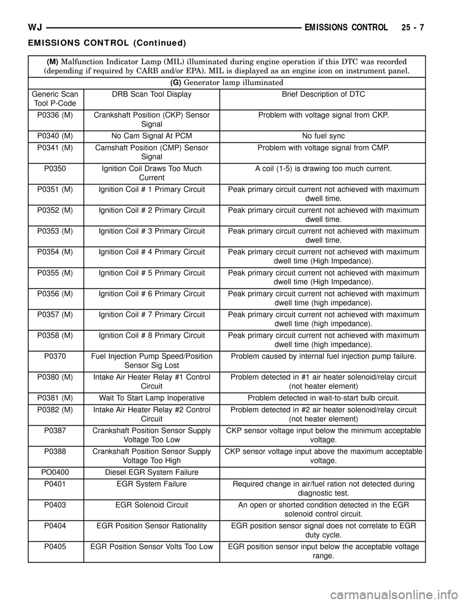
(M)Malfunction Indicator Lamp (MIL) illuminated during engine operation if this DTC was recorded
(depending if required by CARB and/or EPA). MIL is displayed as an engine icon on instrument panel.
(G)Generator lamp illuminated
Generic Scan
Tool P-CodeDRB Scan Tool Display Brief Description of DTC
P0336 (M) Crankshaft Position (CKP) Sensor
SignalProblem with voltage signal from CKP.
P0340 (M) No Cam Signal At PCM No fuel sync
P0341 (M) Camshaft Position (CMP) Sensor
SignalProblem with voltage signal from CMP.
P0350 Ignition Coil Draws Too Much
CurrentA coil (1-5) is drawing too much current.
P0351 (M) Ignition Coil # 1 Primary Circuit Peak primary circuit current not achieved with maximum
dwell time.
P0352 (M) Ignition Coil # 2 Primary Circuit Peak primary circuit current not achieved with maximum
dwell time.
P0353 (M) Ignition Coil # 3 Primary Circuit Peak primary circuit current not achieved with maximum
dwell time.
P0354 (M) Ignition Coil # 4 Primary Circuit Peak primary circuit current not achieved with maximum
dwell time (High Impedance).
P0355 (M) Ignition Coil # 5 Primary Circuit Peak primary circuit current not achieved with maximum
dwell time (High Impedance).
P0356 (M) Ignition Coil # 6 Primary Circuit Peak primary circuit current not achieved with maximum
dwell time (high impedance).
P0357 (M) Ignition Coil # 7 Primary Circuit Peak primary circuit current not achieved with maximum
dwell time (high impedance).
P0358 (M) Ignition Coil # 8 Primary Circuit Peak primary circuit current not achieved with maximum
dwell time (high impedance).
P0370 Fuel Injection Pump Speed/Position
Sensor Sig LostProblem caused by internal fuel injection pump failure.
P0380 (M) Intake Air Heater Relay #1 Control
CircuitProblem detected in #1 air heater solenoid/relay circuit
(not heater element)
P0381 (M) Wait To Start Lamp Inoperative Problem detected in wait-to-start bulb circuit.
P0382 (M) Intake Air Heater Relay #2 Control
CircuitProblem detected in #2 air heater solenoid/relay circuit
(not heater element)
P0387 Crankshaft Position Sensor Supply
Voltage Too LowCKP sensor voltage input below the minimum acceptable
voltage.
P0388 Crankshaft Position Sensor Supply
Voltage Too HighCKP sensor voltage input above the maximum acceptable
voltage.
PO0400 Diesel EGR System Failure
P0401 EGR System Failure Required change in air/fuel ration not detected during
diagnostic test.
P0403 EGR Solenoid Circuit An open or shorted condition detected in the EGR
solenoid control circuit.
P0404 EGR Position Sensor Rationality EGR position sensor signal does not correlate to EGR
duty cycle.
P0405 EGR Position Sensor Volts Too Low EGR position sensor input below the acceptable voltage
range.
WJEMISSIONS CONTROL 25 - 7
EMISSIONS CONTROL (Continued)
Page 2166 of 2199
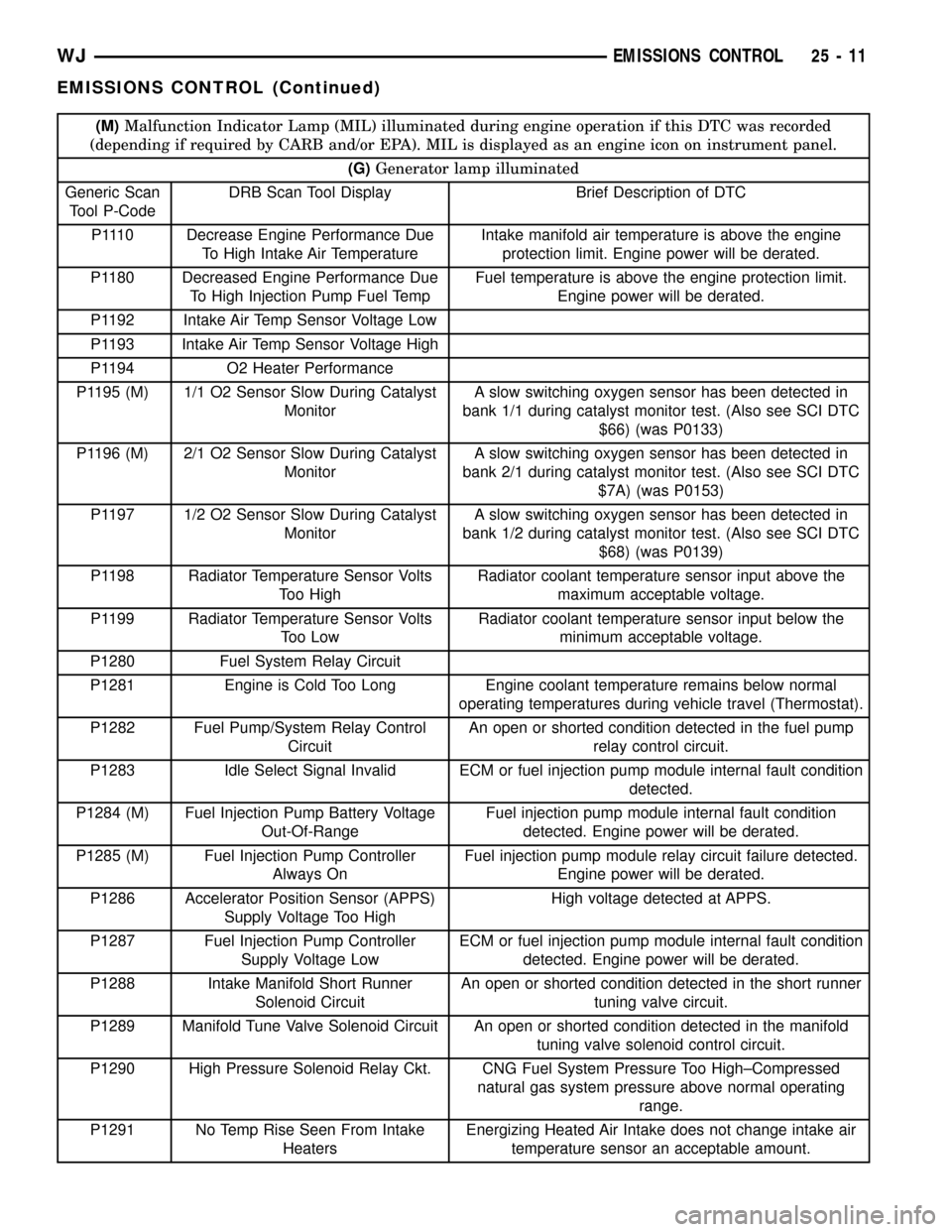
(M)Malfunction Indicator Lamp (MIL) illuminated during engine operation if this DTC was recorded
(depending if required by CARB and/or EPA). MIL is displayed as an engine icon on instrument panel.
(G)Generator lamp illuminated
Generic Scan
Tool P-CodeDRB Scan Tool Display Brief Description of DTC
P1110 Decrease Engine Performance Due
To High Intake Air TemperatureIntake manifold air temperature is above the engine
protection limit. Engine power will be derated.
P1180 Decreased Engine Performance Due
To High Injection Pump Fuel TempFuel temperature is above the engine protection limit.
Engine power will be derated.
P1192 Intake Air Temp Sensor Voltage Low
P1193 Intake Air Temp Sensor Voltage High
P1194 O2 Heater Performance
P1195 (M) 1/1 O2 Sensor Slow During Catalyst
MonitorA slow switching oxygen sensor has been detected in
bank 1/1 during catalyst monitor test. (Also see SCI DTC
$66) (was P0133)
P1196 (M) 2/1 O2 Sensor Slow During Catalyst
MonitorA slow switching oxygen sensor has been detected in
bank 2/1 during catalyst monitor test. (Also see SCI DTC
$7A) (was P0153)
P1197 1/2 O2 Sensor Slow During Catalyst
MonitorA slow switching oxygen sensor has been detected in
bank 1/2 during catalyst monitor test. (Also see SCI DTC
$68) (was P0139)
P1198 Radiator Temperature Sensor Volts
Too HighRadiator coolant temperature sensor input above the
maximum acceptable voltage.
P1199 Radiator Temperature Sensor Volts
Too LowRadiator coolant temperature sensor input below the
minimum acceptable voltage.
P1280 Fuel System Relay Circuit
P1281 Engine is Cold Too Long Engine coolant temperature remains below normal
operating temperatures during vehicle travel (Thermostat).
P1282 Fuel Pump/System Relay Control
CircuitAn open or shorted condition detected in the fuel pump
relay control circuit.
P1283 Idle Select Signal Invalid ECM or fuel injection pump module internal fault condition
detected.
P1284 (M) Fuel Injection Pump Battery Voltage
Out-Of-RangeFuel injection pump module internal fault condition
detected. Engine power will be derated.
P1285 (M) Fuel Injection Pump Controller
Always OnFuel injection pump module relay circuit failure detected.
Engine power will be derated.
P1286 Accelerator Position Sensor (APPS)
Supply Voltage Too HighHigh voltage detected at APPS.
P1287 Fuel Injection Pump Controller
Supply Voltage LowECM or fuel injection pump module internal fault condition
detected. Engine power will be derated.
P1288 Intake Manifold Short Runner
Solenoid CircuitAn open or shorted condition detected in the short runner
tuning valve circuit.
P1289 Manifold Tune Valve Solenoid Circuit An open or shorted condition detected in the manifold
tuning valve solenoid control circuit.
P1290 High Pressure Solenoid Relay Ckt. CNG Fuel System Pressure Too High±Compressed
natural gas system pressure above normal operating
range.
P1291 No Temp Rise Seen From Intake
HeatersEnergizing Heated Air Intake does not change intake air
temperature sensor an acceptable amount.
WJEMISSIONS CONTROL 25 - 11
EMISSIONS CONTROL (Continued)