2003 JEEP GRAND CHEROKEE fuel pump
[x] Cancel search: fuel pumpPage 1440 of 2199
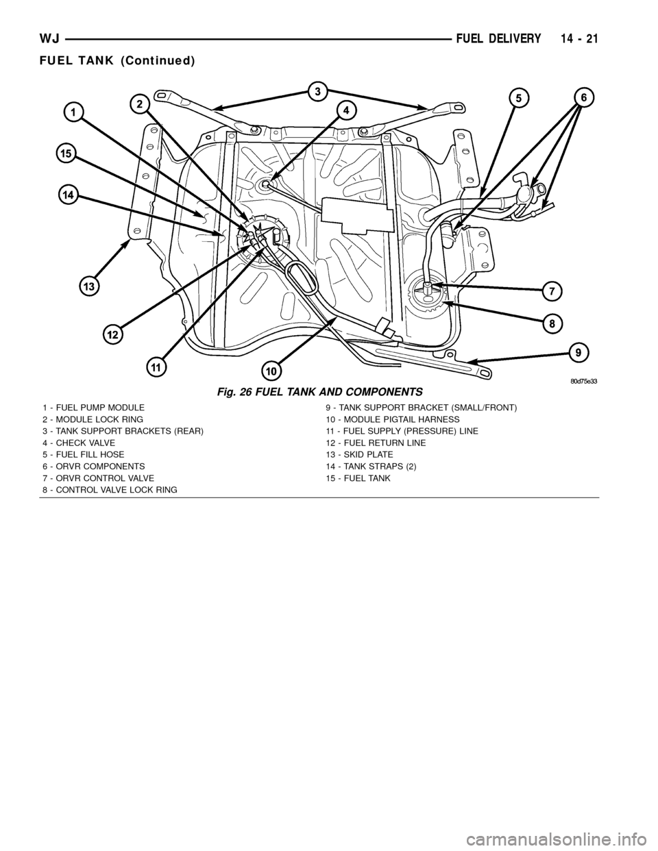
Fig. 26 FUEL TANK AND COMPONENTS
1 - FUEL PUMP MODULE 9 - TANK SUPPORT BRACKET (SMALL/FRONT)
2 - MODULE LOCK RING 10 - MODULE PIGTAIL HARNESS
3 - TANK SUPPORT BRACKETS (REAR) 11 - FUEL SUPPLY (PRESSURE) LINE
4 - CHECK VALVE 12 - FUEL RETURN LINE
5 - FUEL FILL HOSE 13 - SKID PLATE
6 - ORVR COMPONENTS 14 - TANK STRAPS (2)
7 - ORVR CONTROL VALVE 15 - FUEL TANK
8 - CONTROL VALVE LOCK RING
WJFUEL DELIVERY 14 - 21
FUEL TANK (Continued)
Page 1446 of 2199
INLET FILTER
REMOVAL
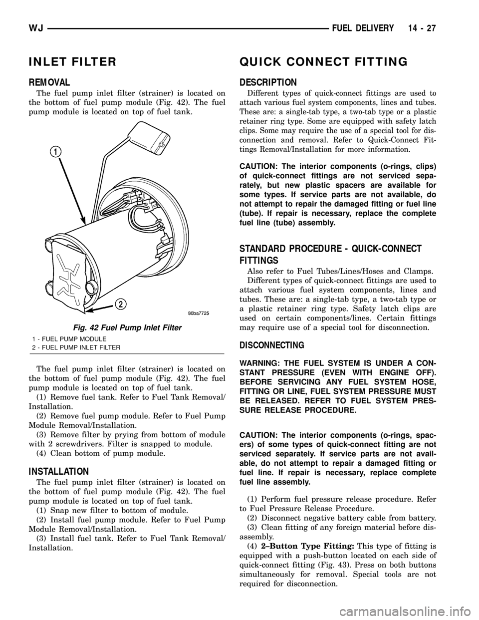
The fuel pump inlet filter (strainer) is located on
the bottom of fuel pump module (Fig. 42). The fuel
pump module is located on top of fuel tank.
The fuel pump inlet filter (strainer) is located on
the bottom of fuel pump module (Fig. 42). The fuel
pump module is located on top of fuel tank.
(1) Remove fuel tank. Refer to Fuel Tank Removal/
Installation.
(2) Remove fuel pump module. Refer to Fuel Pump
Module Removal/Installation.
(3) Remove filter by prying from bottom of module
with 2 screwdrivers. Filter is snapped to module.
(4) Clean bottom of pump module.
INSTALLATION
The fuel pump inlet filter (strainer) is located on
the bottom of fuel pump module (Fig. 42). The fuel
pump module is located on top of fuel tank.
(1) Snap new filter to bottom of module.
(2) Install fuel pump module. Refer to Fuel Pump
Module Removal/Installation.
(3) Install fuel tank. Refer to Fuel Tank Removal/
Installation.
QUICK CONNECT FITTING
DESCRIPTION
Different types of quick-connect fittings are used to
attach various fuel system components, lines and tubes.
These are: a single-tab type, a two-tab type or a plastic
retainer ring type. Some are equipped with safety latch
clips. Some may require the use of a special tool for dis-
connection and removal. Refer to Quick-Connect Fit-
tings Removal/Installation for more information.
CAUTION: The interior components (o-rings, clips)
of quick-connect fittings are not serviced sepa-
rately, but new plastic spacers are available for
some types. If service parts are not available, do
not attempt to repair the damaged fitting or fuel line
(tube). If repair is necessary, replace the complete
fuel line (tube) assembly.
STANDARD PROCEDURE - QUICK-CONNECT
FITTINGS
Also refer to Fuel Tubes/Lines/Hoses and Clamps.
Different types of quick-connect fittings are used to
attach various fuel system components, lines and
tubes. These are: a single-tab type, a two-tab type or
a plastic retainer ring type. Safety latch clips are
used on certain components/lines. Certain fittings
may require use of a special tool for disconnection.
DISCONNECTING
WARNING: THE FUEL SYSTEM IS UNDER A CON-
STANT PRESSURE (EVEN WITH ENGINE OFF).
BEFORE SERVICING ANY FUEL SYSTEM HOSE,
FITTING OR LINE, FUEL SYSTEM PRESSURE MUST
BE RELEASED. REFER TO FUEL SYSTEM PRES-
SURE RELEASE PROCEDURE.
CAUTION: The interior components (o-rings, spac-
ers) of some types of quick-connect fitting are not
serviced separately. If service parts are not avail-
able, do not attempt to repair a damaged fitting or
fuel line. If repair is necessary, replace complete
fuel line assembly.
(1) Perform fuel pressure release procedure. Refer
to Fuel Pressure Release Procedure.
(2) Disconnect negative battery cable from battery.
(3) Clean fitting of any foreign material before dis-
assembly.
(4)2±Button Type Fitting:This type of fitting is
equipped with a push-button located on each side of
quick-connect fitting (Fig. 43). Press on both buttons
simultaneously for removal. Special tools are not
required for disconnection.
Fig. 42 Fuel Pump Inlet Filter
1 - FUEL PUMP MODULE
2 - FUEL PUMP INLET FILTER
WJFUEL DELIVERY 14 - 27
Page 1450 of 2199
FUEL INJECTION
TABLE OF CONTENTS
page page
FUEL INJECTION
DIAGNOSIS AND TESTING
VISUAL INSPECTION..................32
SPECIFICATIONS
TORQUE - FUEL INJECTION.............39
ACCELERATOR PEDAL
REMOVAL.............................39
INSTALLATION.........................39
CRANKSHAFT POSITION SENSOR
DESCRIPTION
DESCRIPTION - 4.0L...................40
DESCRIPTION - 4.7L...................40
OPERATION
OPERATION - 4.0L....................40
OPERATION - 4.7L....................41
REMOVAL
REMOVAL - 4.0L......................41
REMOVAL - 4.7L......................41
INSTALLATION
INSTALLATION - 4.0L..................42
INSTALLATION - 4.7L..................43
FUEL INJECTOR
DESCRIPTION.........................43
OPERATION
OPERATION.........................43
OPERATION - PCM OUTPUT............43
DIAGNOSIS AND TESTING - FUEL INJECTOR . 44
REMOVAL.............................44
INSTALLATION.........................44
FUEL PUMP RELAY
DESCRIPTION.........................44
OPERATION...........................44
IDLE AIR CONTROL MOTOR
DESCRIPTION.........................44
OPERATION...........................44
REMOVAL
REMOVAL - 4.0L......................45
REMOVAL - 4.7L......................45
INSTALLATION
INSTALLATION - 4.0L..................46
INSTALLATION - 4.7L..................46
INTAKE AIR TEMPERATURE SENSOR
DESCRIPTION.........................46
OPERATION...........................46
REMOVAL
REMOVAL - 4.0L......................46
REMOVAL - 4.7L......................46
INSTALLATION
INSTALLATION - 4.0L..................47INSTALLATION - 4.7L..................47
MAP SENSOR
DESCRIPTION
DESCRIPTION........................48
DESCRIPTION - 4.7L...................48
OPERATION...........................48
REMOVAL
REMOVAL - 4.0L......................48
REMOVAL - 4.7L......................49
INSTALLATION
INSTALLATION - 4.0L..................49
INSTALLATION - 4.7L..................49
O2S HEATER RELAY
DESCRIPTION.........................49
OPERATION...........................49
REMOVAL.............................50
INSTALLATION.........................50
O2S SENSOR
DESCRIPTION.........................50
OPERATION...........................50
REMOVAL.............................51
INSTALLATION.........................51
THROTTLE BODY
DESCRIPTION.........................52
OPERATION...........................52
REMOVAL
REMOVAL - 4.0L......................52
REMOVAL - 4.7L......................53
INSTALLATION
INSTALLATION - 4.0L..................53
INSTALLATION - 4.7L..................54
THROTTLE CONTROL CABLE
REMOVAL
REMOVAL - 4.0L......................54
REMOVAL - 4.7L......................55
INSTALLATION
INSTALLATION ± 4.0L..................55
INSTALLATION - 4.7L..................56
THROTTLE POSITION SENSOR
DESCRIPTION.........................56
OPERATION...........................56
REMOVAL
REMOVAL - 4.0L......................57
REMOVAL - 4.7L......................57
INSTALLATION
INSTALLATION - 4.0L..................58
INSTALLATION - 4.7L..................58
WJFUEL INJECTION 14 - 31
Page 1451 of 2199
FUEL INJECTION
DIAGNOSIS AND TESTING
VISUAL INSPECTION
A visual inspection for loose, disconnected or incor-
rectly routed wires, vacuum lines and hoses should
be made. This should be done before attempting to
diagnose or service the fuel injection system. A visual
check will help spot these faults and save unneces-
sary test and diagnostic time. A thorough visual
inspection will include the following checks:
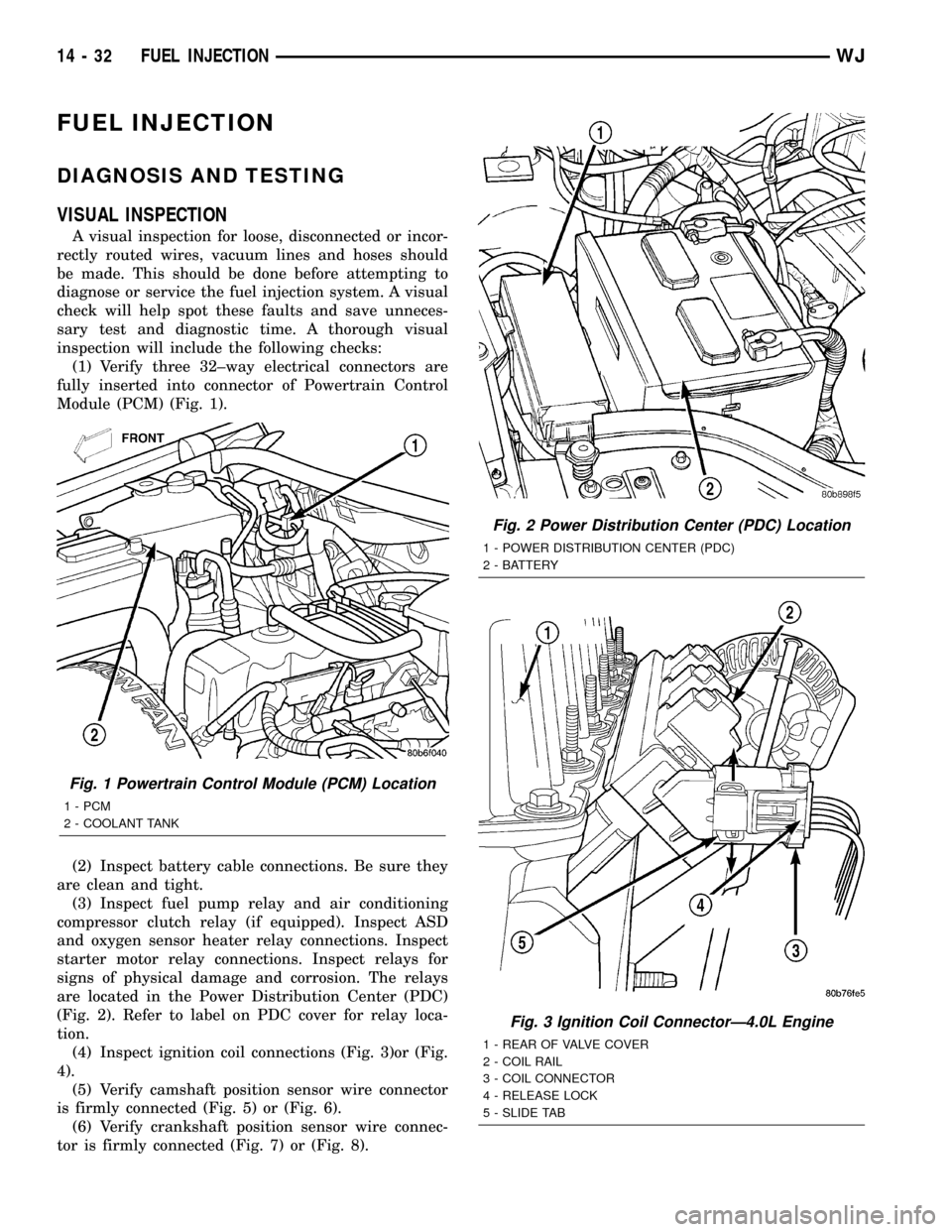
(1) Verify three 32±way electrical connectors are
fully inserted into connector of Powertrain Control
Module (PCM) (Fig. 1).
(2) Inspect battery cable connections. Be sure they
are clean and tight.
(3) Inspect fuel pump relay and air conditioning
compressor clutch relay (if equipped). Inspect ASD
and oxygen sensor heater relay connections. Inspect
starter motor relay connections. Inspect relays for
signs of physical damage and corrosion. The relays
are located in the Power Distribution Center (PDC)
(Fig. 2). Refer to label on PDC cover for relay loca-
tion.
(4) Inspect ignition coil connections (Fig. 3)or (Fig.
4).
(5) Verify camshaft position sensor wire connector
is firmly connected (Fig. 5) or (Fig. 6).
(6) Verify crankshaft position sensor wire connec-
tor is firmly connected (Fig. 7) or (Fig. 8).
Fig. 1 Powertrain Control Module (PCM) Location
1 - PCM
2 - COOLANT TANK
Fig. 2 Power Distribution Center (PDC) Location
1 - POWER DISTRIBUTION CENTER (PDC)
2 - BATTERY
Fig. 3 Ignition Coil ConnectorÐ4.0L Engine
1 - REAR OF VALVE COVER
2 - COIL RAIL
3 - COIL CONNECTOR
4 - RELEASE LOCK
5 - SLIDE TAB
14 - 32 FUEL INJECTIONWJ
Page 1457 of 2199
(23) Inspect for pinched or leaking fuel tubes/lines.
Inspect for pinched, cracked or leaking fuel hoses.
(24) Inspect for exhaust system restrictions such
as pinched exhaust pipes, collapsed muffler or
plugged catalytic convertor.
(25) If equipped with automatic transmission, ver-
ify electrical harness is firmly connected to park/neu-
tral switch and to transmission components.
(26) Verify fuel pump module pigtail harness elec-
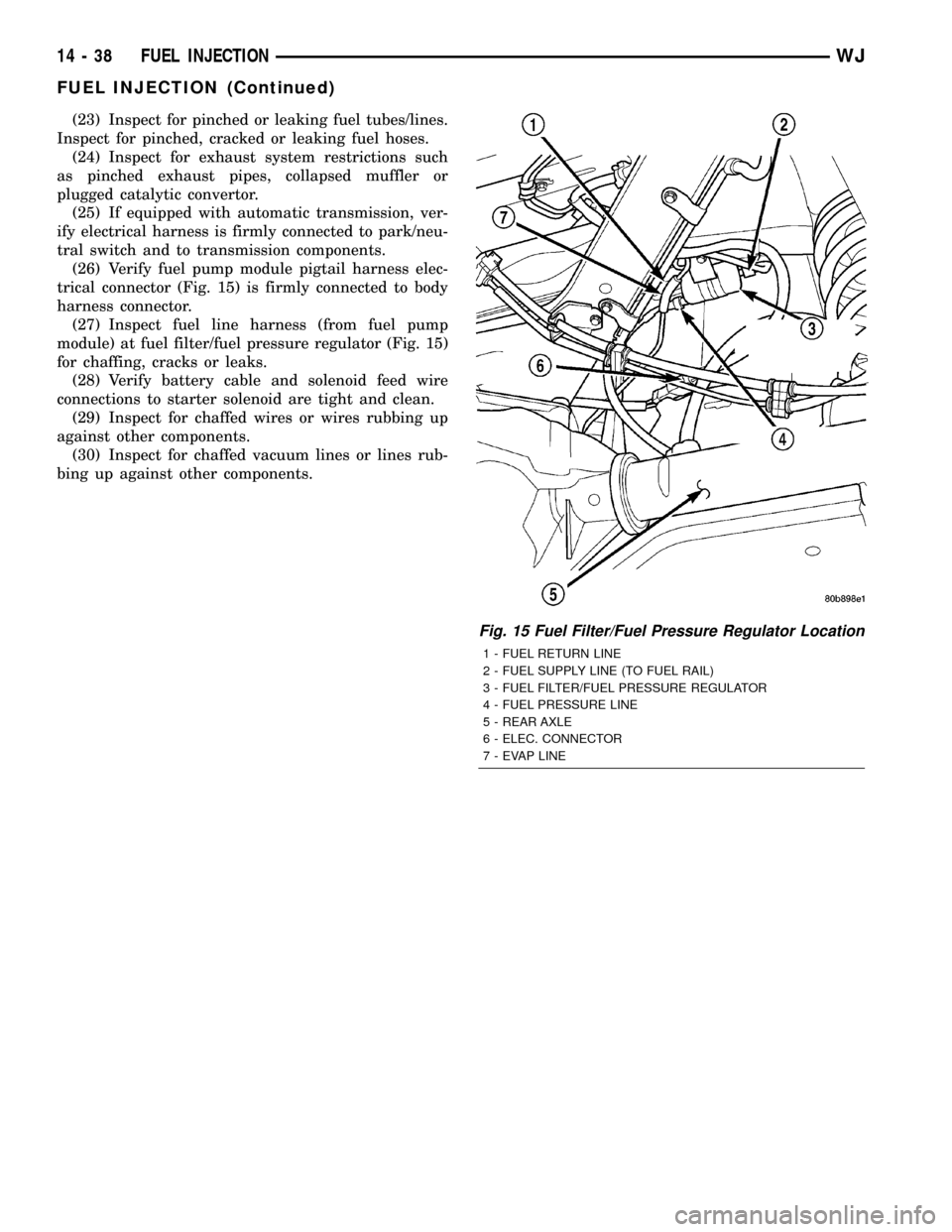
trical connector (Fig. 15) is firmly connected to body
harness connector.
(27) Inspect fuel line harness (from fuel pump
module) at fuel filter/fuel pressure regulator (Fig. 15)
for chaffing, cracks or leaks.
(28) Verify battery cable and solenoid feed wire
connections to starter solenoid are tight and clean.
(29) Inspect for chaffed wires or wires rubbing up
against other components.
(30) Inspect for chaffed vacuum lines or lines rub-
bing up against other components.
Fig. 15 Fuel Filter/Fuel Pressure Regulator Location
1 - FUEL RETURN LINE
2 - FUEL SUPPLY LINE (TO FUEL RAIL)
3 - FUEL FILTER/FUEL PRESSURE REGULATOR
4 - FUEL PRESSURE LINE
5 - REAR AXLE
6 - ELEC. CONNECTOR
7 - EVAP LINE
14 - 38 FUEL INJECTIONWJ
FUEL INJECTION (Continued)
Page 1463 of 2199
The PCM determines injector on-time (pulse width)
based on various inputs.
DIAGNOSIS AND TESTING - FUEL INJECTOR
To perform a complete test of the fuel injectors and
their circuitry, use the DRB scan tool and refer to the
appropriate Powertrain Diagnostics Procedures man-
ual. To test the injector only, refer to the following:
Disconnect the fuel injector wire harness connector
from the injector. The injector is equipped with 2
electrical terminals (pins). Place an ohmmeter across
the terminals. Resistance reading should be approxi-
mately 12 ohms 1.2 ohms at 20ÉC (68ÉF).
REMOVAL
WARNING: THE FUEL SYSTEM IS UNDER CON-
STANT PRESSURE EVEN WITH ENGINE OFF.
BEFORE SERVICING FUEL INJECTOR(S), FUEL
SYSTEM PRESSURE MUST BE RELEASED.
To remove one or more fuel injectors, the fuel rail
assembly must be removed from engine.
(1) Perform Fuel System Pressure Release Proce-
dure.
(2) Remove fuel injector rail. Refer to Fuel Injector
Rail Removal/Installation.
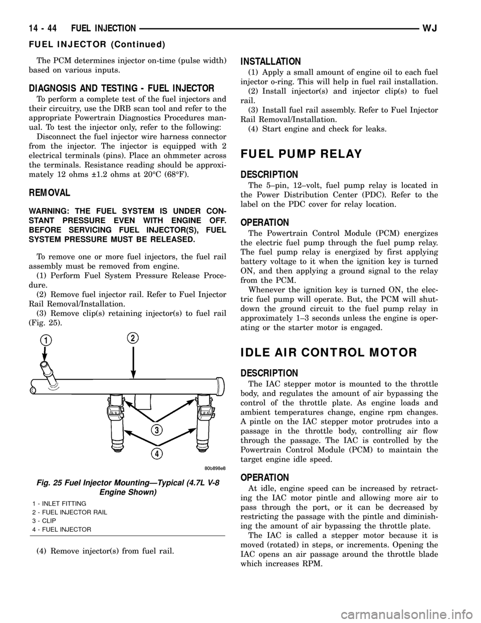
(3) Remove clip(s) retaining injector(s) to fuel rail
(Fig. 25).
(4) Remove injector(s) from fuel rail.
INSTALLATION
(1) Apply a small amount of engine oil to each fuel
injector o-ring. This will help in fuel rail installation.
(2) Install injector(s) and injector clip(s) to fuel
rail.
(3) Install fuel rail assembly. Refer to Fuel Injector
Rail Removal/Installation.
(4) Start engine and check for leaks.
FUEL PUMP RELAY
DESCRIPTION
The 5±pin, 12±volt, fuel pump relay is located in
the Power Distribution Center (PDC). Refer to the
label on the PDC cover for relay location.
OPERATION
The Powertrain Control Module (PCM) energizes
the electric fuel pump through the fuel pump relay.
The fuel pump relay is energized by first applying
battery voltage to it when the ignition key is turned
ON, and then applying a ground signal to the relay
from the PCM.
Whenever the ignition key is turned ON, the elec-
tric fuel pump will operate. But, the PCM will shut-
down the ground circuit to the fuel pump relay in
approximately 1±3 seconds unless the engine is oper-
ating or the starter motor is engaged.
IDLE AIR CONTROL MOTOR
DESCRIPTION
The IAC stepper motor is mounted to the throttle
body, and regulates the amount of air bypassing the
control of the throttle plate. As engine loads and
ambient temperatures change, engine rpm changes.
A pintle on the IAC stepper motor protrudes into a
passage in the throttle body, controlling air flow
through the passage. The IAC is controlled by the
Powertrain Control Module (PCM) to maintain the
target engine idle speed.
OPERATION
At idle, engine speed can be increased by retract-
ing the IAC motor pintle and allowing more air to
pass through the port, or it can be decreased by
restricting the passage with the pintle and diminish-
ing the amount of air bypassing the throttle plate.
The IAC is called a stepper motor because it is
moved (rotated) in steps, or increments. Opening the
IAC opens an air passage around the throttle blade
which increases RPM.Fig. 25 Fuel Injector MountingÐTypical (4.7L V-8
Engine Shown)
1 - INLET FITTING
2 - FUEL INJECTOR RAIL
3 - CLIP
4 - FUEL INJECTOR
14 - 44 FUEL INJECTIONWJ
FUEL INJECTOR (Continued)
Page 1524 of 2199
IDENTIFICATION
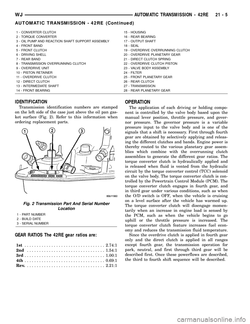
Transmission identification numbers are stamped
on the left side of the case just above the oil pan gas-
ket surface (Fig. 2). Refer to this information when
ordering replacement parts.
GEAR RATIOS The 42RE gear ratios are:
1st.................................2.74:1
2nd................................1.54:1
3rd.................................1.00:1
4th.................................0.69:1
Rev.................................2.21:1
OPERATION
The application of each driving or holding compo-
nent is controlled by the valve body based upon the
manual lever position, throttle pressure, and gover-
nor pressure. The governor pressure is a variable
pressure input to the valve body and is one of the
signals that a shift is necessary. First through fourth
gear are obtained by selectively applying and releas-
ing the different clutches and bands. Engine power is
thereby routed to the various planetary gear assem-
blies which combine with the overrunning clutch
assemblies to generate the different gear ratios. The
torque converter clutch is hydraulically applied and
is released when fluid is vented from the hydraulic
circuit by the torque converter control (TCC) solenoid
on the valve body. The torque converter clutch is con-
trolled by the Powertrain Control Module (PCM). The
torque converter clutch engages in fourth gear, and
in third gear under various conditions, such as when
the O/D switch is OFF, when the vehicle is cruising
on a level surface after the vehicle has warmed up.
The torque converter clutch will disengage momen-
tarily when an increase in engine load is sensed by
the PCM, such as when the vehicle begins to go
uphill or the throttle pressure is increased. The
torque converter clutch feature increases fuel econ-
omy and reduces the transmission fluid temperature.
Since the overdrive clutch is applied in fourth gear
only and the direct clutch is applied in all ranges
except fourth gear, the transmission operation for
park, neutral, and first through third gear will be
described first. Once these powerflows are described,
the third to fourth shift sequence will be described.
1 - CONVERTER CLUTCH 15 - HOUSING
2 - TORQUE CONVERTER 16 - REAR BEARING
3 - OIL PUMP AND REACTION SHAFT SUPPORT ASSEMBLY 17 - OUTPUT SHAFT
4 - FRONT BAND 18 - SEAL
5 - FRONT CLUTCH 19 - OVERDRIVE OVERRUNNING CLUTCH
6 - DRIVING SHELL 20 - OVERDRIVE PLANETARY GEAR
7 - REAR BAND 21 - DIRECT CLUTCH SPRING
8 - TRANSMISSION OVERRUNNING CLUTCH 22 - OVERDRIVE CLUTCH PISTON
9 - OVERDRIVE UNIT 23 - VALVE BODY ASSEMBLY
10 - PISTON RETAINER 24 - FILTER
11 - OVERDRIVE CLUTCH 25 - FRONT PLANETARY GEAR
12 - DIRECT CLUTCH 26 - REAR CLUTCH
13 - INTERMEDIATE SHAFT 27 - TRANSMISSION
14 - FRONT BEARING 28 - REAR PLANETARY GEAR
Fig. 2 Transmission Part And Serial Number
Location
1 - PART NUMBER
2 - BUILD DATE
3 - SERIAL NUMBER
WJAUTOMATIC TRANSMISSION - 42RE 21 - 5
AUTOMATIC TRANSMISSION - 42RE (Continued)
Page 1546 of 2199
REMOVAL
The overdrive unit can be removed and serviced
separately. It is not necessary to remove the entire
transmission assembly to perform overdrive unit
repairs.
If only the overdrive unit requires service, refer to
Overdrive Removal for proper procedures.
CAUTION: The transmission and torque converter
must be removed as an assembly to avoid compo-
nent damage. The converter driveplate, pump bush-
ing, or oil seal can be damaged if the converter is
left attached to the driveplate during removal. Be
sure to remove the transmission and converter as
an assembly.
(1) Disconnect battery negative cable.
(2) Disconnect and lower or remove necessary
exhaust components.
(3) Disconnect fluid cooler lines at transmission.
(4) Remove starter motor. (Refer to 8 - ELECTRI-
CAL/STARTING/STARTER MOTOR - REMOVAL)
(5) Disconnect and remove crankshaft position sen-
sor. (Refer to 14 - FUEL SYSTEM/FUEL INJEC-
TION/CRANKSHAFT POSITION SENSOR -
REMOVAL) Retain sensor attaching bolts.
CAUTION: The crankshaft position sensor will be
damaged if the transmission is removed, or
installed, while the sensor is still bolted to the
engine block, or transmission (4.0L only). To avoid
damage, be sure to remove the sensor before
removing the transmission.
(6) Remove the bolts holding the bell housing
brace to the transmission.
(7) Remove nut holding the bell housing brace to
the engine to transmission bending brace.
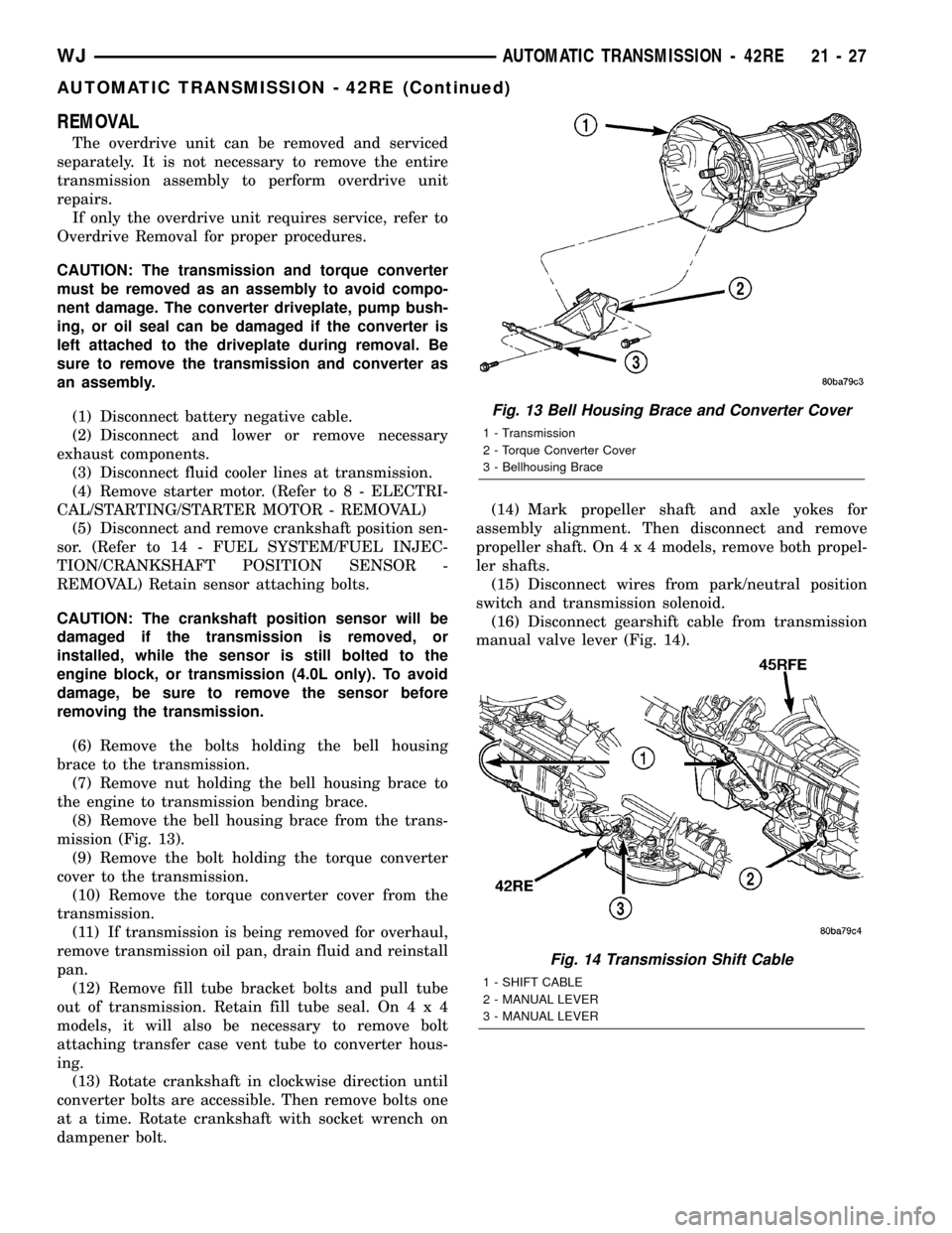
(8) Remove the bell housing brace from the trans-
mission (Fig. 13).
(9) Remove the bolt holding the torque converter
cover to the transmission.
(10) Remove the torque converter cover from the
transmission.
(11) If transmission is being removed for overhaul,
remove transmission oil pan, drain fluid and reinstall
pan.
(12) Remove fill tube bracket bolts and pull tube
out of transmission. Retain fill tube seal. On4x4
models, it will also be necessary to remove bolt
attaching transfer case vent tube to converter hous-
ing.
(13) Rotate crankshaft in clockwise direction until
converter bolts are accessible. Then remove bolts one
at a time. Rotate crankshaft with socket wrench on
dampener bolt.(14) Mark propeller shaft and axle yokes for
assembly alignment. Then disconnect and remove
propeller shaft. On4x4models, remove both propel-
ler shafts.
(15) Disconnect wires from park/neutral position
switch and transmission solenoid.
(16) Disconnect gearshift cable from transmission
manual valve lever (Fig. 14).
Fig. 13 Bell Housing Brace and Converter Cover
1 - Transmission
2 - Torque Converter Cover
3 - Bellhousing Brace
Fig. 14 Transmission Shift Cable
1 - SHIFT CABLE
2 - MANUAL LEVER
3 - MANUAL LEVER
WJAUTOMATIC TRANSMISSION - 42RE 21 - 27
AUTOMATIC TRANSMISSION - 42RE (Continued)