2003 JEEP GRAND CHEROKEE cylinder head cover
[x] Cancel search: cylinder head coverPage 1386 of 2199
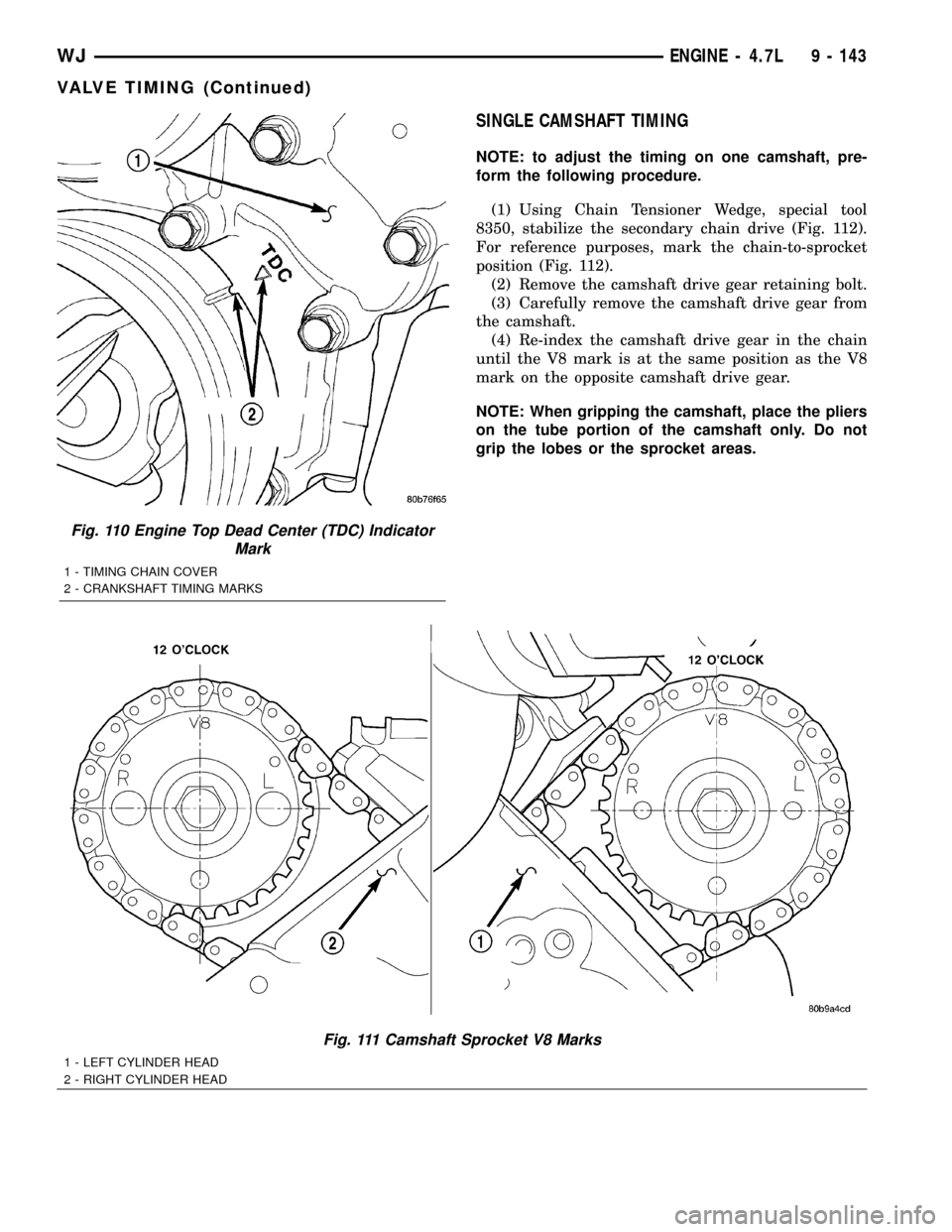
SINGLE CAMSHAFT TIMING
NOTE: to adjust the timing on one camshaft, pre-
form the following procedure.
(1) Using Chain Tensioner Wedge, special tool
8350, stabilize the secondary chain drive (Fig. 112).
For reference purposes, mark the chain-to-sprocket
position (Fig. 112).
(2) Remove the camshaft drive gear retaining bolt.
(3) Carefully remove the camshaft drive gear from
the camshaft.
(4) Re-index the camshaft drive gear in the chain
until the V8 mark is at the same position as the V8
mark on the opposite camshaft drive gear.
NOTE: When gripping the camshaft, place the pliers
on the tube portion of the camshaft only. Do not
grip the lobes or the sprocket areas.
Fig. 110 Engine Top Dead Center (TDC) Indicator
Mark
1 - TIMING CHAIN COVER
2 - CRANKSHAFT TIMING MARKS
Fig. 111 Camshaft Sprocket V8 Marks
1 - LEFT CYLINDER HEAD
2 - RIGHT CYLINDER HEAD
WJENGINE - 4.7L 9 - 143
VALVE TIMING (Continued)
Page 1387 of 2199
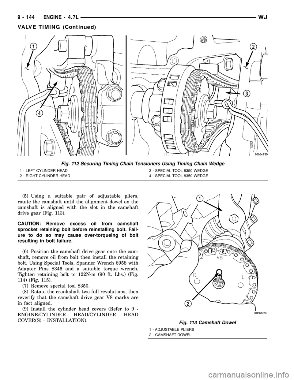
(5) Using a suitable pair of adjustable pliers,
rotate the camshaft until the alignment dowel on the
camshaft is aligned with the slot in the camshaft
drive gear (Fig. 113).
CAUTION: Remove excess oil from camshaft
sprocket retaining bolt before reinstalling bolt. Fail-
ure to do so may cause over-torqueing of bolt
resulting in bolt failure.
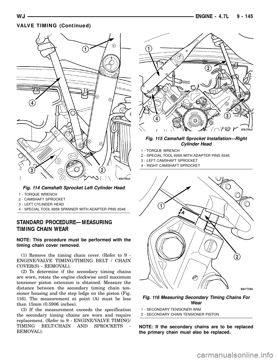
(6) Position the camshaft drive gear onto the cam-
shaft, remove oil from bolt then install the retaining
bolt. Using Special Tools, Spanner Wrench 6958 with
Adapter Pins 8346 and a suitable torque wrench,
Tighten retaining bolt to 122N´m (90 ft. Lbs.) (Fig.
114) (Fig. 115).
(7) Remove special tool 8350.
(8) Rotate the crankshaft two full revolutions, then
reverify that the camshaft drive gear V8 marks are
in fact aligned.
(9) Install the cylinder head covers (Refer to 9 -
ENGINE/CYLINDER HEAD/CYLINDER HEAD
COVER(S) - INSTALLATION).
Fig. 112 Securing Timing Chain Tensioners Using Timing Chain Wedge
1 - LEFT CYLINDER HEAD
2 - RIGHT CYLINDER HEAD3 - SPECIAL TOOL 8350 WEDGE
4 - SPECIAL TOOL 8350 WEDGE
Fig. 113 Camshaft Dowel
1 - ADJUSTABLE PLIERS
2 - CAMSHAFT DOWEL
9 - 144 ENGINE - 4.7LWJ
VALVE TIMING (Continued)
Page 1388 of 2199
STANDARD PROCEDUREÐMEASURING
TIMING CHAIN WEAR
NOTE: This procedure must be performed with the
timing chain cover removed.
(1) Remove the timing chain cover. (Refer to 9 -
ENGINE/VALVE TIMING/TIMING BELT / CHAIN
COVER(S) - REMOVAL).
(2) To determine if the secondary timing chains
are worn, rotate the engine clockwise until maximum
tensioner piston extension is obtained. Measure the
distance between the secondary timing chain ten-
sioner housing and the step ledge on the piston (Fig.
116). The measurement at point (A) must be less
than 15mm (0.5906 inches).
(3) If the measurement exceeds the specification
the secondary timing chains are worn and require
replacement. (Refer to 9 - ENGINE/VALVE TIMING/
TIMING BELT/CHAIN AND SPROCKETS -
REMOVAL).NOTE: If the secondary chains are to be replaced
the primary chain must also be replaced.
Fig. 114 Camshaft Sprocket Left Cylinder Head
1 - TORQUE WRENCH
2 - CAMSHAFT SPROCKET
3 - LEFT CYLINDER HEAD
4 - SPECIAL TOOL 6958 SPANNER WITH ADAPTER PINS 8346
Fig. 115 Camshaft Sprocket InstallationÐRight
Cylinder Head
1 - TORQUE WRENCH
2 - SPECIAL TOOL 6958 WITH ADAPTER PINS 8346
3 - LEFT CAMSHAFT SPROCKET
4 - RIGHT CAMSHAFT SPROCKET
Fig. 116 Measuring Secondary Timing Chains For
Wear
1 - SECONDARY TENSIONER ARM
2 - SECONDARY CHAIN TENSIONER PISTON
WJENGINE - 4.7L 9 - 145
VALVE TIMING (Continued)
Page 1390 of 2199
TIMING BELT/CHAIN AND
SPROCKETS
REMOVAL
(1) Disconnect negative cable from battery.
(2) Drain cooling system (Refer to 7 - COOLING -
STANDARD PROCEDURE).
(3) Remove right and left cylinder head covers
(Refer to 9 - ENGINE/CYLINDER HEAD/CYLIN-
DER HEAD COVER(S) - REMOVAL).
(4) Remove radiator fan (Refer to 7 - COOLING/
ENGINE/RADIATOR FAN - REMOVAL).
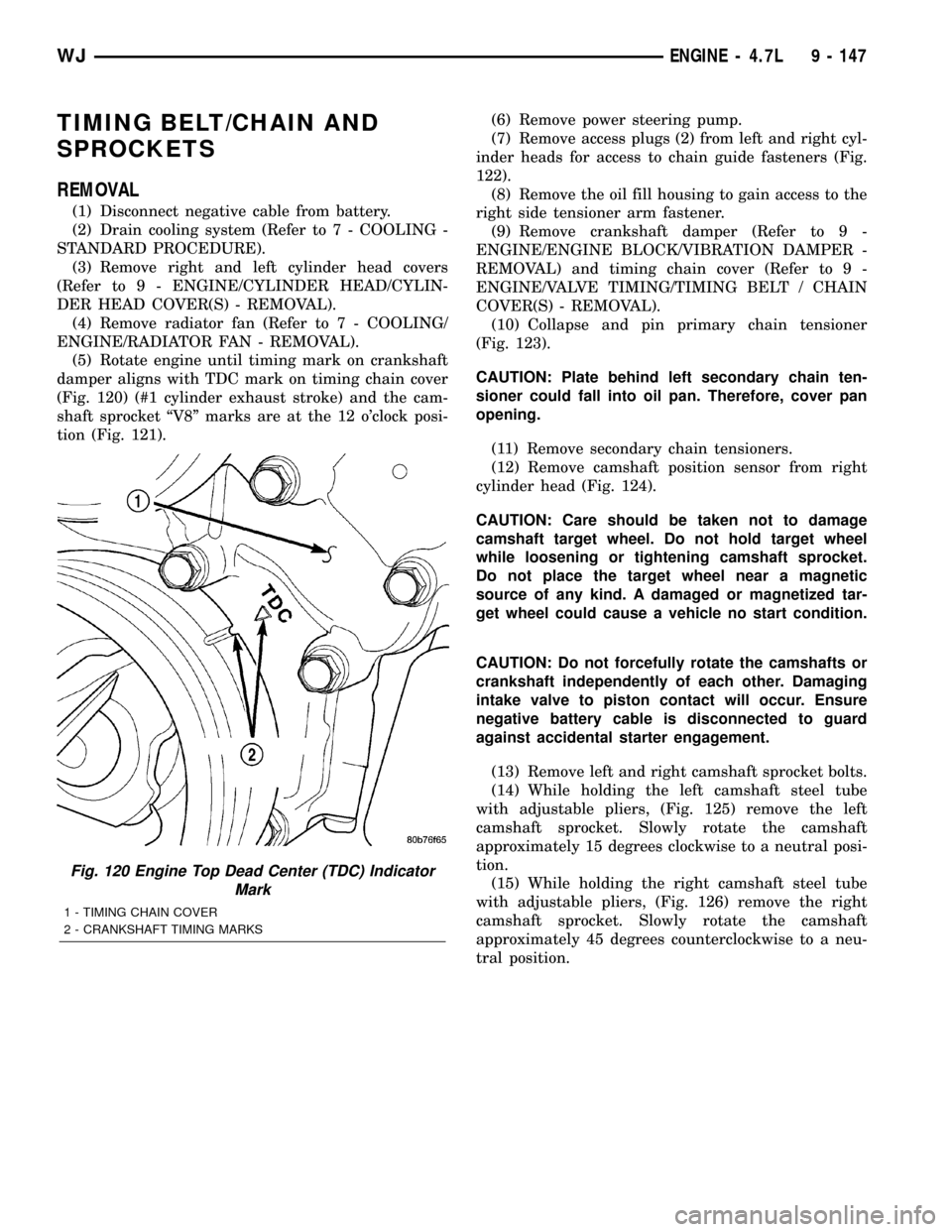
(5) Rotate engine until timing mark on crankshaft
damper aligns with TDC mark on timing chain cover
(Fig. 120) (#1 cylinder exhaust stroke) and the cam-
shaft sprocket ªV8º marks are at the 12 o'clock posi-
tion (Fig. 121).(6) Remove power steering pump.
(7) Remove access plugs (2) from left and right cyl-
inder heads for access to chain guide fasteners (Fig.
122).
(8) Remove the oil fill housing to gain access to the
right side tensioner arm fastener.
(9) Remove crankshaft damper (Refer to 9 -
ENGINE/ENGINE BLOCK/VIBRATION DAMPER -
REMOVAL) and timing chain cover (Refer to 9 -
ENGINE/VALVE TIMING/TIMING BELT / CHAIN
COVER(S) - REMOVAL).
(10) Collapse and pin primary chain tensioner
(Fig. 123).
CAUTION: Plate behind left secondary chain ten-
sioner could fall into oil pan. Therefore, cover pan
opening.
(11) Remove secondary chain tensioners.
(12) Remove camshaft position sensor from right
cylinder head (Fig. 124).
CAUTION: Care should be taken not to damage
camshaft target wheel. Do not hold target wheel
while loosening or tightening camshaft sprocket.
Do not place the target wheel near a magnetic
source of any kind. A damaged or magnetized tar-
get wheel could cause a vehicle no start condition.
CAUTION: Do not forcefully rotate the camshafts or
crankshaft independently of each other. Damaging
intake valve to piston contact will occur. Ensure
negative battery cable is disconnected to guard
against accidental starter engagement.
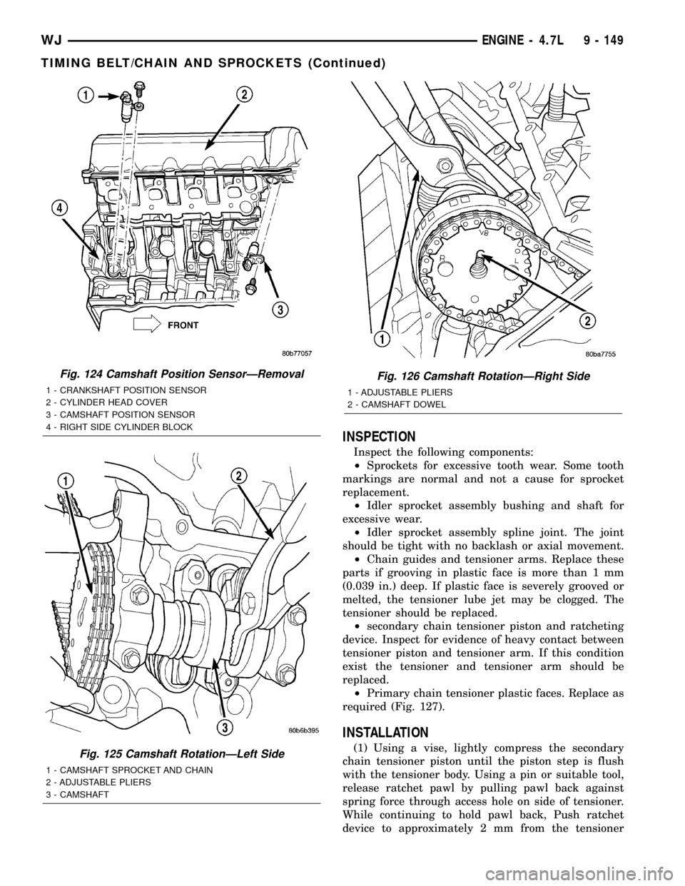
(13) Remove left and right camshaft sprocket bolts.
(14) While holding the left camshaft steel tube
with adjustable pliers, (Fig. 125) remove the left
camshaft sprocket. Slowly rotate the camshaft
approximately 15 degrees clockwise to a neutral posi-
tion.
(15) While holding the right camshaft steel tube
with adjustable pliers, (Fig. 126) remove the right
camshaft sprocket. Slowly rotate the camshaft
approximately 45 degrees counterclockwise to a neu-
tral position.
Fig. 120 Engine Top Dead Center (TDC) Indicator
Mark
1 - TIMING CHAIN COVER
2 - CRANKSHAFT TIMING MARKS
WJENGINE - 4.7L 9 - 147
Page 1392 of 2199
INSPECTION
Inspect the following components:
²Sprockets for excessive tooth wear. Some tooth
markings are normal and not a cause for sprocket
replacement.
²Idler sprocket assembly bushing and shaft for
excessive wear.
²Idler sprocket assembly spline joint. The joint
should be tight with no backlash or axial movement.
²Chain guides and tensioner arms. Replace these
parts if grooving in plastic face is more than 1 mm
(0.039 in.) deep. If plastic face is severely grooved or
melted, the tensioner lube jet may be clogged. The
tensioner should be replaced.
²secondary chain tensioner piston and ratcheting
device. Inspect for evidence of heavy contact between
tensioner piston and tensioner arm. If this condition
exist the tensioner and tensioner arm should be
replaced.
²Primary chain tensioner plastic faces. Replace as
required (Fig. 127).
INSTALLATION
(1) Using a vise, lightly compress the secondary
chain tensioner piston until the piston step is flush
with the tensioner body. Using a pin or suitable tool,
release ratchet pawl by pulling pawl back against
spring force through access hole on side of tensioner.
While continuing to hold pawl back, Push ratchet
device to approximately 2 mm from the tensioner
Fig. 124 Camshaft Position SensorÐRemoval
1 - CRANKSHAFT POSITION SENSOR
2 - CYLINDER HEAD COVER
3 - CAMSHAFT POSITION SENSOR
4 - RIGHT SIDE CYLINDER BLOCK
Fig. 125 Camshaft RotationÐLeft Side
1 - CAMSHAFT SPROCKET AND CHAIN
2 - ADJUSTABLE PLIERS
3 - CAMSHAFT
Fig. 126 Camshaft RotationÐRight Side
1 - ADJUSTABLE PLIERS
2 - CAMSHAFT DOWEL
WJENGINE - 4.7L 9 - 149
TIMING BELT/CHAIN AND SPROCKETS (Continued)
Page 1396 of 2199
(22) Install timing chain cover (Refer to 9 -
ENGINE/VALVE TIMING/TIMING BELT / CHAIN
COVER(S) - INSTALLATION) and crankshaft
damper (Refer to 9 - ENGINE/ENGINE BLOCK/VI-
BRATION DAMPER - INSTALLATION).
(23) Install cylinder head covers (Refer to 9 -
ENGINE/CYLINDER HEAD/CYLINDER HEAD
COVER(S) - INSTALLATION).
NOTE: Before installing threaded plug in right cylin-
der head, the plug must be coated with sealant to
prevent leaks.
(24) Coat the large threaded access plug with
MopartThread Sealant with Teflon, then install
into the right cylinder head and tighten to 81 N´m
(60 ft. lbs.) (Fig. 122).
(25) Install the oil fill housing.
(26) Install access plug in left cylinder head (Fig.
122).
(27) Install power steering pump.
(28) Install radiator fan (Refer to 7 - COOLING/
ENGINE/RADIATOR FAN - INSTALLATION).
(29) Fill cooling system (Refer to 7 - COOLING -
STANDARD PROCEDURE).
(30) Connect negative cable to battery.
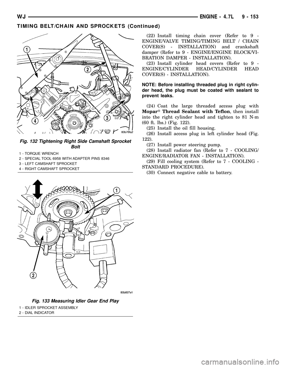
Fig. 132 Tightening Right Side Camshaft Sprocket
Bolt
1 - TORQUE WRENCH
2 - SPECIAL TOOL 6958 WITH ADAPTER PINS 8346
3 - LEFT CAMSHAFT SPROCKET
4 - RIGHT CAMSHAFT SPROCKET
Fig. 133 Measuring Idler Gear End Play
1 - IDLER SPROCKET ASSEMBLY
2 - DIAL INDICATOR
WJENGINE - 4.7L 9 - 153
TIMING BELT/CHAIN AND SPROCKETS (Continued)
Page 2135 of 2199

The high pressure relief valve vents only enough
refrigerant to reduce the system pressure, and then
re-seats itself. The majority of the refrigerant is con-
served in the system. If the valve vents refrigerant, it
does not mean that the valve is faulty.
The high pressure relief valve is a factory-cali-
brated unit. The valve cannot be adjusted or
repaired, and must not be removed or otherwise dis-
turbed. The valve is only serviced as a part of the
compressor assembly.
DIAGNOSIS AND TESTING - COMPRESSOR
NOISE
When investigating an air conditioning related
noise, you must first know the conditions under
which the noise occurs. These conditions include:
weather, vehicle speed, transmission in gear or neu-
tral, engine speed, engine temperature, and any
other special conditions. Noises that develop during
air conditioning operation can often be misleading.
For example: What sounds like a failed front bearing
or connecting rod, may be caused by loose bolts, nuts,
mounting brackets, or a loose compressor clutch
assembly.
Drive belts are speed sensitive. At different engine
speeds and depending upon belt tension, belts can
develop noises that are mistaken for a compressor
noise. Improper belt tension can cause a misleading
noise when the compressor clutch is engaged, which
may not occur when the compressor clutch is disen-
gaged. Check the serpentine drive belt condition and
tension as described in Cooling before beginning this
procedure.
(1) Select a quiet area for testing. Duplicate the
complaint conditions as much as possible. Switch the
compressor on and off several times to clearly iden-
tify the compressor noise. Listen to the compressor
while the clutch is engaged and disengaged. Probe
the compressor with an engine stethoscope or a long
screwdriver with the handle held to your ear to bet-
ter localize the source of the noise.
(2) Loosen all of the compressor mounting hard-
ware and retighten. Tighten the compressor clutch
mounting nut. Be certain that the clutch coil is
mounted securely to the compressor, and that the
clutch plate and pulley are properly aligned and have
the correct air gap. (Refer to 24 - HEATING & AIR
CONDITIONING/CONTROLS/A/C COMPRESSOR
CLUTCH - INSTALLATION)
(3) To duplicate a high-ambient temperature condi-
tion (high head pressure), restrict the air flow
through the condenser. Install a manifold gauge set
to be certain that the discharge pressure does not
exceed 2760 kPa (400 psi).
(4) Check the refrigerant system plumbing for
incorrect routing, rubbing or interference, which cancause unusual noises. Also check the refrigerant lines
for kinks or sharp bends that will restrict refrigerant
flow, which can cause noises. (Refer to 24 - HEAT-
ING & AIR CONDITIONING/PLUMBING - CAU-
TION - REFRIGERANT HOSES/LINES/TUBES
PRECAUTIONS)
(5) If the noise is from opening and closing of the
high pressure relief valve, reclaim, evacuate, and
recharge the refrigerant system. (Refer to 24 - HEAT-
ING & AIR CONDITIONING/PLUMBING - STAN-
DARD PROCEDURE - REFRIGERANT RECOVERY)
(Refer to 24 - HEATING & AIR CONDITIONING/
PLUMBING - STANDARD PROCEDURE - REFRIG-
ERANT SYSTEM EVACUATE) (Refer to 24 -
HEATING & AIR CONDITIONING/PLUMBING -
STANDARD PROCEDURE - REFRIGERANT SYS-
TEM CHARGE)If the high pressure relief valve still
does not seat properly, replace the a/c compressor.
(Refer to 24 - HEATING & AIR CONDITIONING/
PLUMBING/A/C COMPRESSOR - REMOVAL)
(6) If the noise is from liquid slugging on the suc-
tion line, check the refrigerant oil level and the
refrigerant system charge. (Refer to 24 - HEATING
& AIR CONDITIONING/PLUMBING/REFRIGER-
ANT OIL - STANDARD PROCEDURE) (Refer to 24 -
HEATING & AIR CONDITIONING/PLUMBING -
SPECIFICATIONS - CHARGE CAPACITY).
(7) If the noise continues, replace the compressor
and repeat Step 1.
REMOVAL
REMOVAL
The compressor may be removed and repositioned
without disconnecting the refrigerant lines or dis-
charging the refrigerant system. Discharging is not
necessary if servicing the compressor clutch or clutch
coil, the engine, the cylinder head, or the generator.
WARNING: REVIEW THE WARNINGS AND CAU-
TIONS IN THE FRONT OF THIS SECTION BEFORE
PERFORMING THE FOLLOWING OPERATION.
(Refer to 24 - HEATING & AIR CONDITIONING/
PLUMBING - WARNING) (Refer to 24 - HEATING &
AIR CONDITIONING/PLUMBING - CAUTION)
(1) Recover the refrigerant from the system. (Refer
to 24 - HEATING & AIR CONDITIONING/PLUMB-
ING - STANDARD PROCEDURE - REFRIGERANT
RECOVERY)
(2) Disconnect and isolate the battery negative
cable.
(3) Remove the serpentine drive belt. Refer to
Cooling for the procedures.
(4) Unplug the compressor clutch coil wire harness
connector.
24 - 58 PLUMBINGWJ
A/C COMPRESSOR (Continued)
Page 2145 of 2199
REMOVAL - 2.7L TURBO DIESEL
WARNING: REVIEW THE WARNINGS AND CAU-
TIONS IN THE FRONT OF THIS SECTION BEFORE
PERFORMING THE FOLLOWING OPERATION.
(Refer to 24 - HEATING & AIR CONDITIONING/
PLUMBING - WARNING) (Refer to 24 - HEATING &
AIR CONDITIONING/PLUMBING - CAUTION)
(1) Disconnect the negative battery cable.
(2) Recover the refrigerant system. (Refer to 24 -
HEATING & AIR CONDITIONING/PLUMBING -
STANDARD PROCEDURE - REFRIGERANT
RECOVERY)
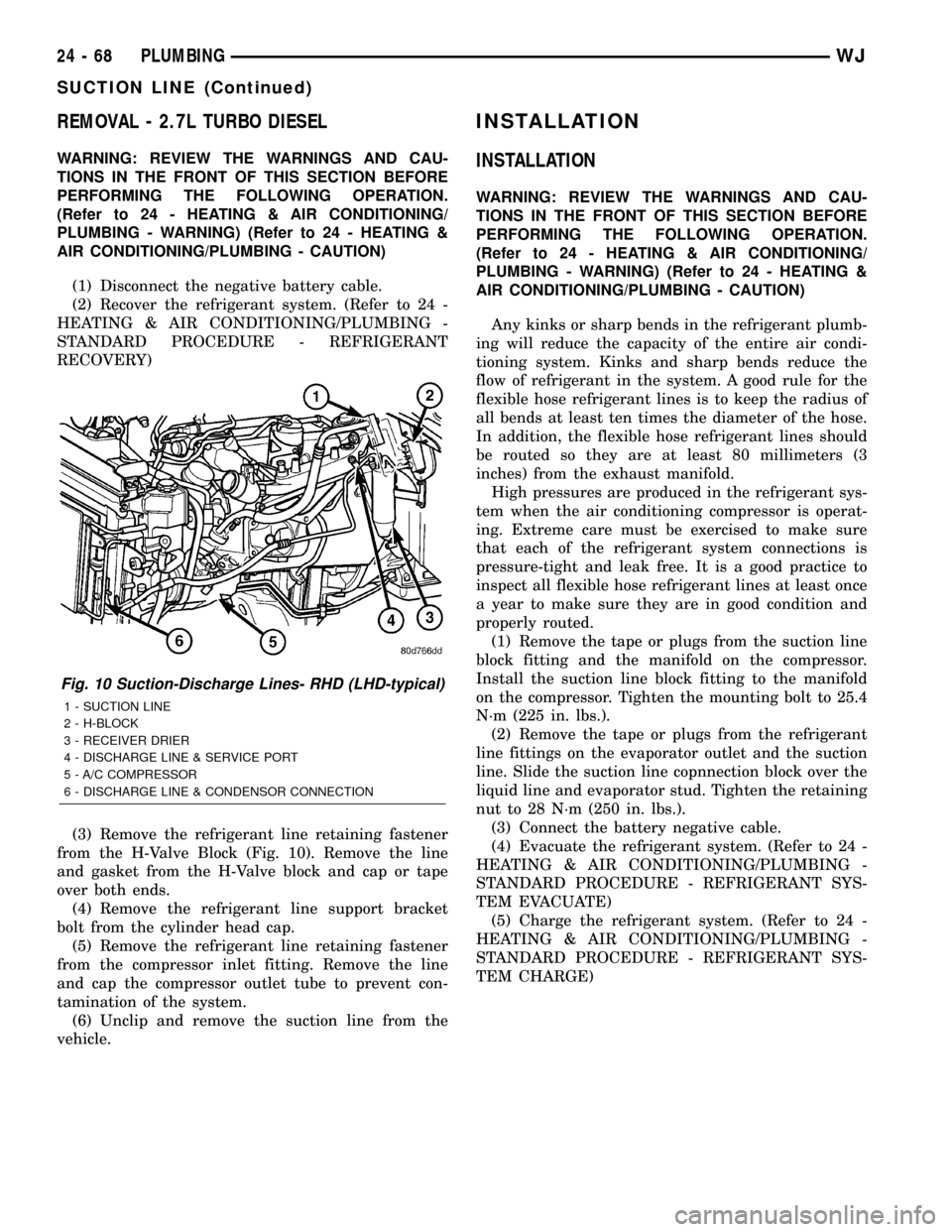
(3) Remove the refrigerant line retaining fastener
from the H-Valve Block (Fig. 10). Remove the line
and gasket from the H-Valve block and cap or tape
over both ends.
(4) Remove the refrigerant line support bracket
bolt from the cylinder head cap.
(5) Remove the refrigerant line retaining fastener
from the compressor inlet fitting. Remove the line
and cap the compressor outlet tube to prevent con-
tamination of the system.
(6) Unclip and remove the suction line from the
vehicle.
INSTALLATION
INSTALLATION
WARNING: REVIEW THE WARNINGS AND CAU-
TIONS IN THE FRONT OF THIS SECTION BEFORE
PERFORMING THE FOLLOWING OPERATION.
(Refer to 24 - HEATING & AIR CONDITIONING/
PLUMBING - WARNING) (Refer to 24 - HEATING &
AIR CONDITIONING/PLUMBING - CAUTION)
Any kinks or sharp bends in the refrigerant plumb-
ing will reduce the capacity of the entire air condi-
tioning system. Kinks and sharp bends reduce the
flow of refrigerant in the system. A good rule for the
flexible hose refrigerant lines is to keep the radius of
all bends at least ten times the diameter of the hose.
In addition, the flexible hose refrigerant lines should
be routed so they are at least 80 millimeters (3
inches) from the exhaust manifold.
High pressures are produced in the refrigerant sys-
tem when the air conditioning compressor is operat-
ing. Extreme care must be exercised to make sure
that each of the refrigerant system connections is
pressure-tight and leak free. It is a good practice to
inspect all flexible hose refrigerant lines at least once
a year to make sure they are in good condition and
properly routed.
(1) Remove the tape or plugs from the suction line
block fitting and the manifold on the compressor.
Install the suction line block fitting to the manifold
on the compressor. Tighten the mounting bolt to 25.4
N´m (225 in. lbs.).
(2) Remove the tape or plugs from the refrigerant
line fittings on the evaporator outlet and the suction
line. Slide the suction line copnnection block over the
liquid line and evaporator stud. Tighten the retaining
nut to 28 N´m (250 in. lbs.).
(3) Connect the battery negative cable.
(4) Evacuate the refrigerant system. (Refer to 24 -
HEATING & AIR CONDITIONING/PLUMBING -
STANDARD PROCEDURE - REFRIGERANT SYS-
TEM EVACUATE)
(5) Charge the refrigerant system. (Refer to 24 -
HEATING & AIR CONDITIONING/PLUMBING -
STANDARD PROCEDURE - REFRIGERANT SYS-
TEM CHARGE)
Fig. 10 Suction-Discharge Lines- RHD (LHD-typical)
1 - SUCTION LINE
2 - H-BLOCK
3 - RECEIVER DRIER
4 - DISCHARGE LINE & SERVICE PORT
5 - A/C COMPRESSOR
6 - DISCHARGE LINE & CONDENSOR CONNECTION
24 - 68 PLUMBINGWJ
SUCTION LINE (Continued)