2003 JEEP GRAND CHEROKEE Bolts
[x] Cancel search: BoltsPage 162 of 2199
DISASSEMBLY
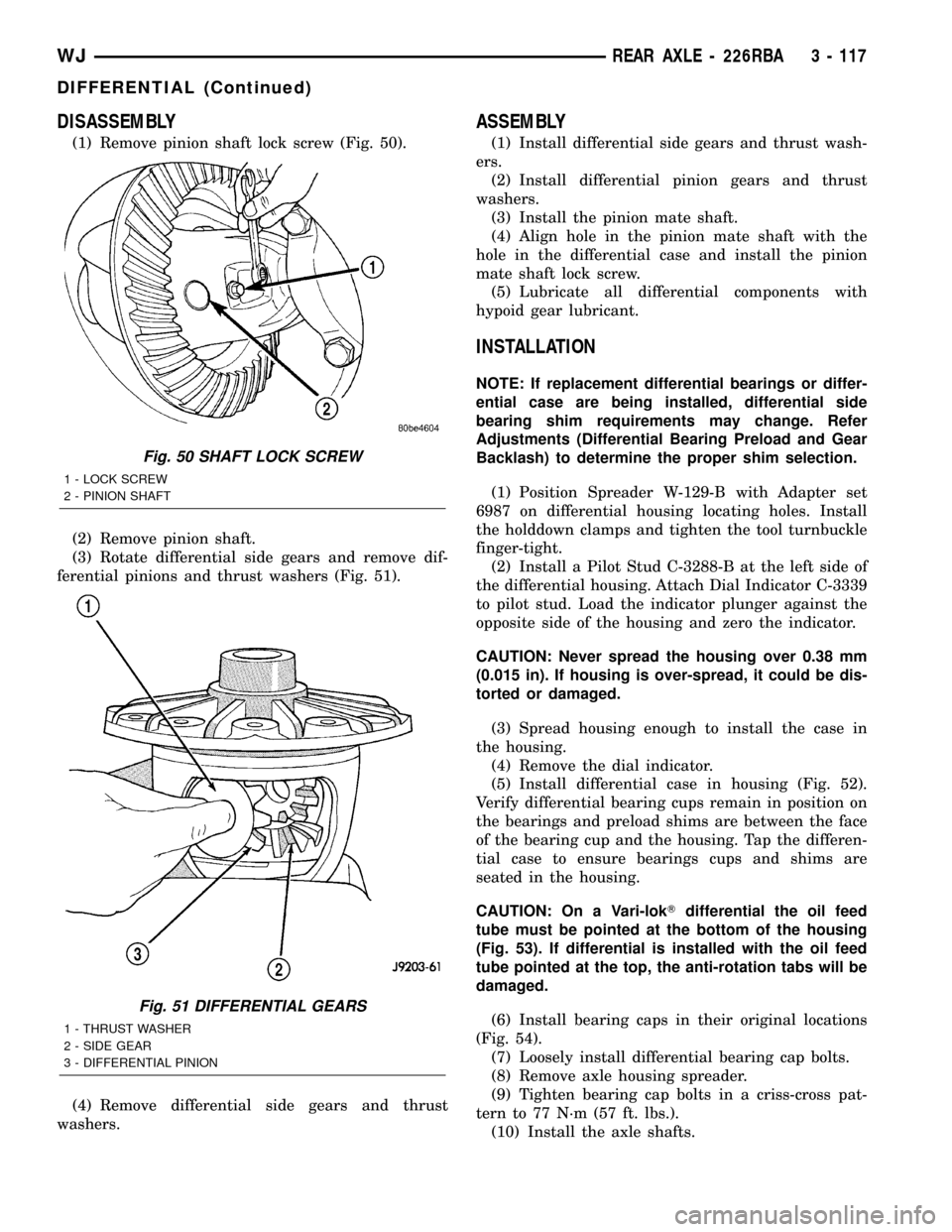
(1) Remove pinion shaft lock screw (Fig. 50).
(2) Remove pinion shaft.
(3) Rotate differential side gears and remove dif-
ferential pinions and thrust washers (Fig. 51).
(4) Remove differential side gears and thrust
washers.
ASSEMBLY
(1) Install differential side gears and thrust wash-
ers.
(2) Install differential pinion gears and thrust
washers.
(3) Install the pinion mate shaft.
(4) Align hole in the pinion mate shaft with the
hole in the differential case and install the pinion
mate shaft lock screw.
(5) Lubricate all differential components with
hypoid gear lubricant.
INSTALLATION
NOTE: If replacement differential bearings or differ-
ential case are being installed, differential side
bearing shim requirements may change. Refer
Adjustments (Differential Bearing Preload and Gear
Backlash) to determine the proper shim selection.
(1) Position Spreader W-129-B with Adapter set
6987 on differential housing locating holes. Install
the holddown clamps and tighten the tool turnbuckle
finger-tight.
(2) Install a Pilot Stud C-3288-B at the left side of
the differential housing. Attach Dial Indicator C-3339
to pilot stud. Load the indicator plunger against the
opposite side of the housing and zero the indicator.
CAUTION: Never spread the housing over 0.38 mm
(0.015 in). If housing is over-spread, it could be dis-
torted or damaged.
(3) Spread housing enough to install the case in
the housing.
(4) Remove the dial indicator.
(5) Install differential case in housing (Fig. 52).
Verify differential bearing cups remain in position on
the bearings and preload shims are between the face
of the bearing cup and the housing. Tap the differen-
tial case to ensure bearings cups and shims are
seated in the housing.
CAUTION: On a Vari-lokTdifferential the oil feed
tube must be pointed at the bottom of the housing
(Fig. 53). If differential is installed with the oil feed
tube pointed at the top, the anti-rotation tabs will be
damaged.
(6) Install bearing caps in their original locations
(Fig. 54).
(7) Loosely install differential bearing cap bolts.
(8) Remove axle housing spreader.
(9) Tighten bearing cap bolts in a criss-cross pat-
tern to 77 N´m (57 ft. lbs.).
(10) Install the axle shafts.
Fig. 50 SHAFT LOCK SCREW
1 - LOCK SCREW
2 - PINION SHAFT
Fig. 51 DIFFERENTIAL GEARS
1 - THRUST WASHER
2 - SIDE GEAR
3 - DIFFERENTIAL PINION
WJREAR AXLE - 226RBA 3 - 117
DIFFERENTIAL (Continued)
Page 164 of 2199
(12) Install cover and tighten bolts in a criss-cross
pattern to 41 N´m (30 ft. lbs.).
(13) Refill the differential with Mopar Hypoid
Gear Lubricant or equivalent to bottom of the fill
plug hole.
(14) Install fill hole plug.
(15) Remove support and lower the vehicle.
DIFFERENTIAL - TRAC-LOK
DIAGNOSIS AND TESTING
The most common problem is a chatter noise when
turning corners. Before removing the unit for repair,
drain, flush and refill the axle with the specified
lubricant. A container of Mopar Trac-loktLubricant
(friction modifier) should be added after repair ser-
vice or during a lubricant change.
After changing the lubricant, drive the vehicle and
make 10 to 12 slow, figure-eight turns. This maneu-
ver will pump lubricant through the clutches. This
will correct the condition in most instances. If the
chatter persists, clutch damage could have occurred.
DIFFERENTIAL TEST
The differential can be tested without removing the
differential case by measuring rotating torque. Make
sure brakes are not dragging during this measure-
ment.
(1) Place blocks in front and rear of both front
wheels.
(2) Raise one rear wheel until it is completely off
the ground.
(3) Engine off, transmission in neutral, and park-
ing brake off.
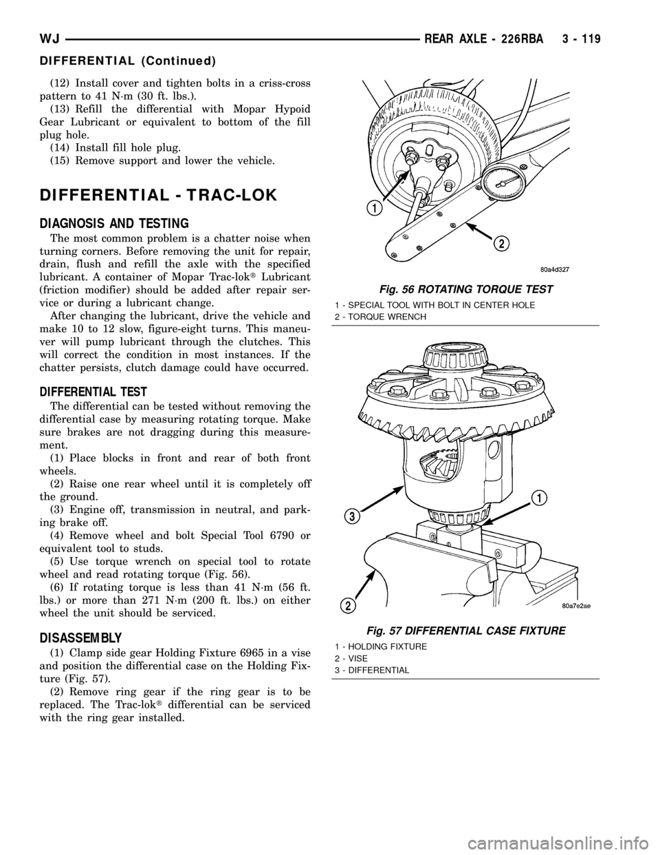
(4) Remove wheel and bolt Special Tool 6790 or
equivalent tool to studs.
(5) Use torque wrench on special tool to rotate
wheel and read rotating torque (Fig. 56).
(6) If rotating torque is less than 41 N´m (56 ft.
lbs.) or more than 271 N´m (200 ft. lbs.) on either
wheel the unit should be serviced.
DISASSEMBLY
(1) Clamp side gear Holding Fixture 6965 in a vise
and position the differential case on the Holding Fix-
ture (Fig. 57).
(2) Remove ring gear if the ring gear is to be
replaced. The Trac-loktdifferential can be serviced
with the ring gear installed.
Fig. 56 ROTATING TORQUE TEST
1 - SPECIAL TOOL WITH BOLT IN CENTER HOLE
2 - TORQUE WRENCH
Fig. 57 DIFFERENTIAL CASE FIXTURE
1 - HOLDING FIXTURE
2 - VISE
3 - DIFFERENTIAL
WJREAR AXLE - 226RBA 3 - 119
DIFFERENTIAL (Continued)
Page 169 of 2199
CAUTION: Vari-lokTplenum must be seated against
the differential case prior to installing the ring gear
side differential bearing.
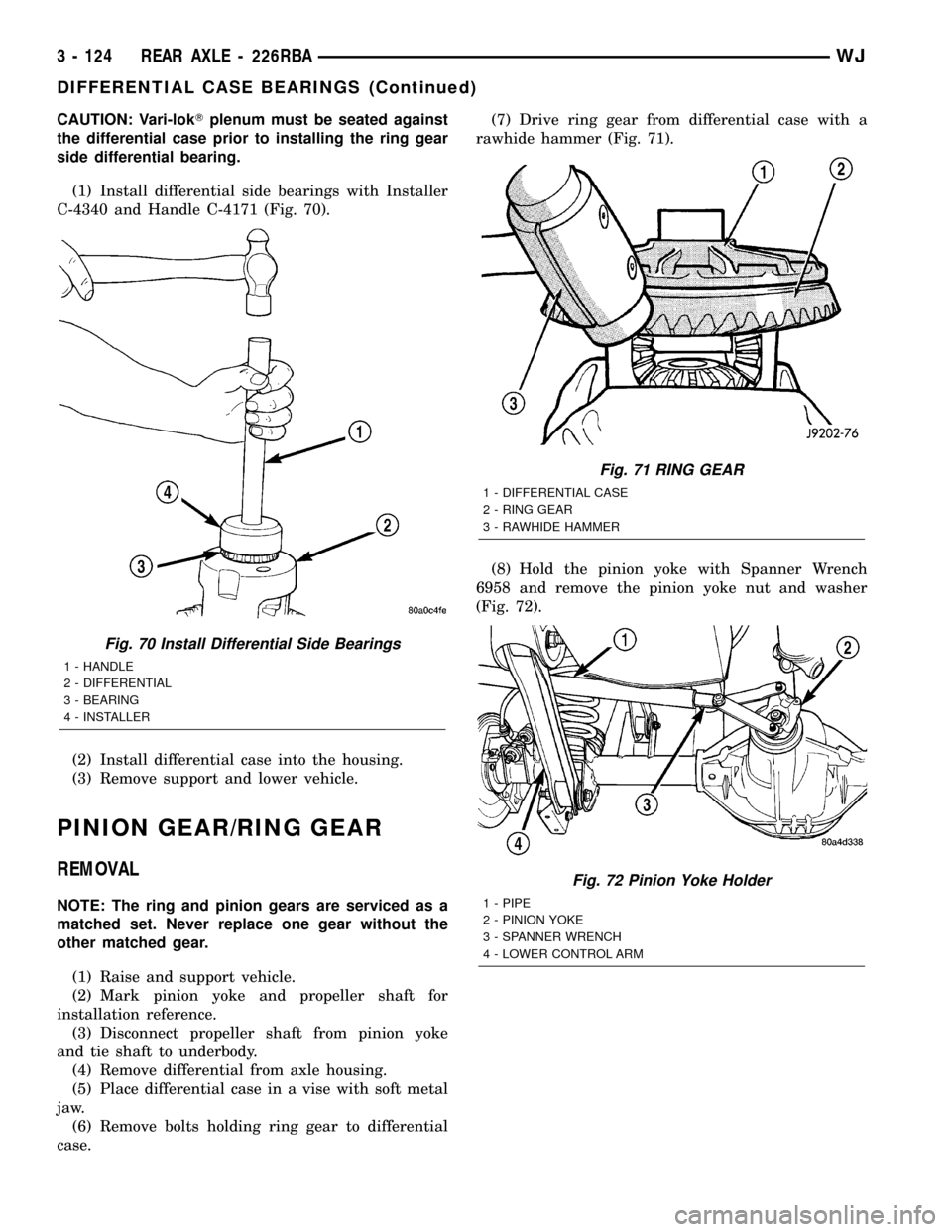
(1) Install differential side bearings with Installer
C-4340 and Handle C-4171 (Fig. 70).
(2) Install differential case into the housing.
(3) Remove support and lower vehicle.
PINION GEAR/RING GEAR
REMOVAL
NOTE: The ring and pinion gears are serviced as a
matched set. Never replace one gear without the
other matched gear.
(1) Raise and support vehicle.
(2) Mark pinion yoke and propeller shaft for
installation reference.
(3) Disconnect propeller shaft from pinion yoke
and tie shaft to underbody.
(4) Remove differential from axle housing.
(5) Place differential case in a vise with soft metal
jaw.
(6) Remove bolts holding ring gear to differential
case.(7) Drive ring gear from differential case with a
rawhide hammer (Fig. 71).
(8) Hold the pinion yoke with Spanner Wrench
6958 and remove the pinion yoke nut and washer
(Fig. 72).
Fig. 70 Install Differential Side Bearings
1 - HANDLE
2 - DIFFERENTIAL
3 - BEARING
4 - INSTALLER
Fig. 71 RING GEAR
1 - DIFFERENTIAL CASE
2 - RING GEAR
3 - RAWHIDE HAMMER
Fig. 72 Pinion Yoke Holder
1 - PIPE
2 - PINION YOKE
3 - SPANNER WRENCH
4 - LOWER CONTROL ARM
3 - 124 REAR AXLE - 226RBAWJ
DIFFERENTIAL CASE BEARINGS (Continued)
Page 174 of 2199
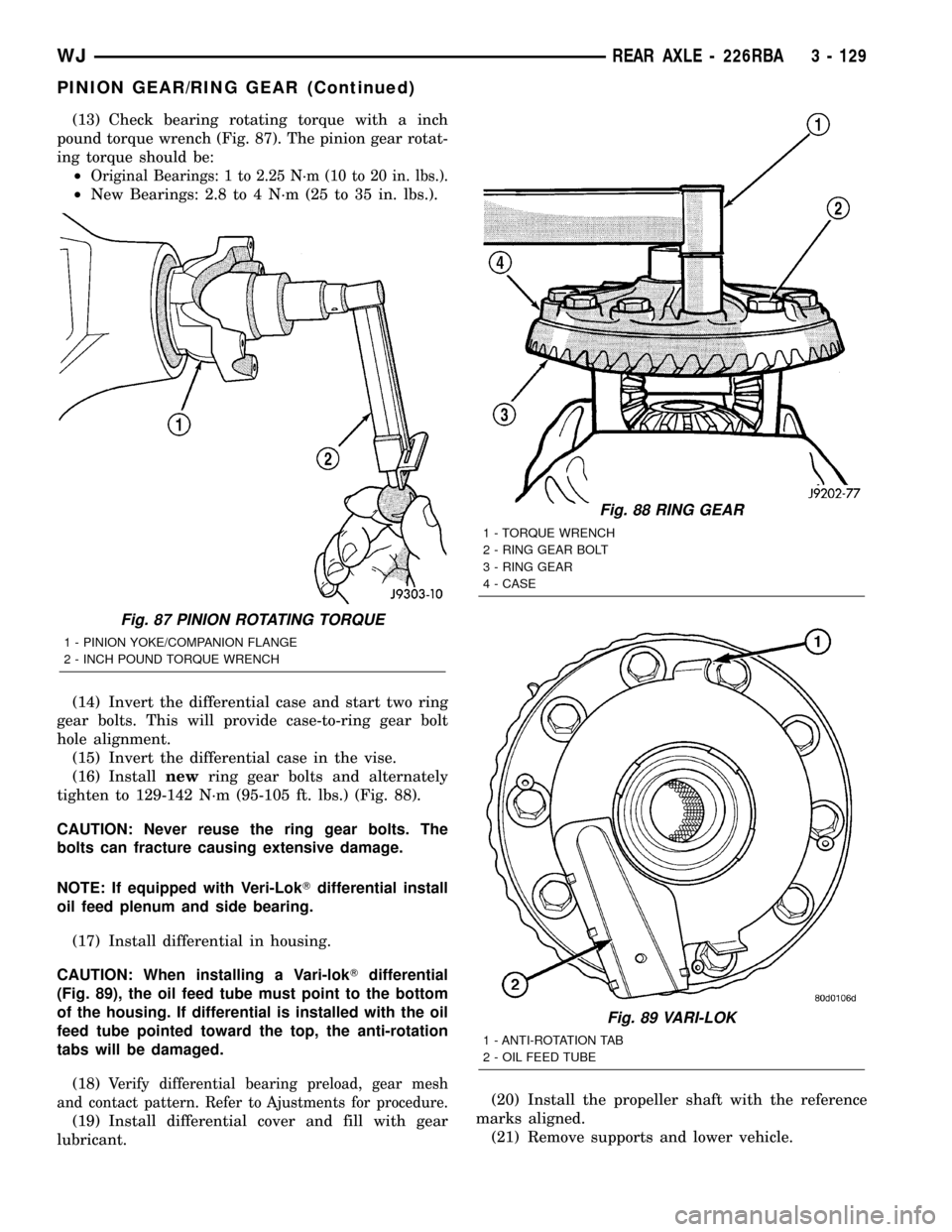
(13) Check bearing rotating torque with a inch
pound torque wrench (Fig. 87). The pinion gear rotat-
ing torque should be:
²
Original Bearings: 1 to 2.25 N´m (10 to 20 in. lbs.).
²New Bearings: 2.8 to 4 N´m (25 to 35 in. lbs.).
(14) Invert the differential case and start two ring
gear bolts. This will provide case-to-ring gear bolt
hole alignment.
(15) Invert the differential case in the vise.
(16) Installnewring gear bolts and alternately
tighten to 129-142 N´m (95-105 ft. lbs.) (Fig. 88).
CAUTION: Never reuse the ring gear bolts. The
bolts can fracture causing extensive damage.
NOTE: If equipped with Veri-LokTdifferential install
oil feed plenum and side bearing.
(17) Install differential in housing.
CAUTION: When installing a Vari-lokTdifferential
(Fig. 89), the oil feed tube must point to the bottom
of the housing. If differential is installed with the oil
feed tube pointed toward the top, the anti-rotation
tabs will be damaged.
(18)
Verify differential bearing preload, gear mesh
and contact pattern. Refer to Ajustments for procedure.
(19) Install differential cover and fill with gear
lubricant.(20) Install the propeller shaft with the reference
marks aligned.
(21) Remove supports and lower vehicle.
Fig. 87 PINION ROTATING TORQUE
1 - PINION YOKE/COMPANION FLANGE
2 - INCH POUND TORQUE WRENCH
Fig. 88 RING GEAR
1 - TORQUE WRENCH
2 - RING GEAR BOLT
3 - RING GEAR
4 - CASE
Fig. 89 VARI-LOK
1 - ANTI-ROTATION TAB
2 - OIL FEED TUBE
WJREAR AXLE - 226RBA 3 - 129
PINION GEAR/RING GEAR (Continued)
Page 181 of 2199
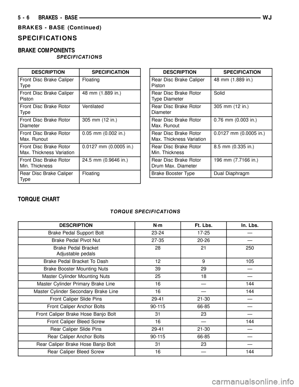
SPECIFICATIONS
BRAKE COMPONENTS
SPECIFICATIONS
DESCRIPTION SPECIFICATION
Front Disc Brake Caliper
TypeFloating
Front Disc Brake Caliper
Piston48 mm (1.889 in.)
Front Disc Brake Rotor
TypeVentilated
Front Disc Brake Rotor
Diameter305 mm (12 in.)
Front Disc Brake Rotor
Max. Runout0.05 mm (0.002 in.)
Front Disc Brake Rotor
Max. Thickness Variation0.0127 mm (0.0005 in.)
Front Disc Brake Rotor
Min. Thickness24.5 mm (0.9646 in.)
Rear Disc Brake Caliper
TypeFloatingDESCRIPTION SPECIFICATION
Rear Disc Brake Caliper
Piston48 mm (1.889 in.)
Rear Disc Brake Rotor
Type DiameterSolid
Rear Disc Brake Rotor
Diameter305 mm (12 in.)
Rear Disc Brake Rotor
Max. Runout0.76 mm (0.003 in.)
Rear Disc Brake Rotor
Max. Thickness Variation0.0127 mm (0.0005 in.)
Rear Disc Brake Rotor
Min. Thickness8.5 mm (0.335 in.)
Rear Disc Brake Rotor
Drum Max. Diameter196 mm (7.7166 in.)
Brake Booster Type Dual Diaphragm
TORQUE CHART
TORQUE SPECIFICATIONS
DESCRIPTION N´m Ft. Lbs. In. Lbs.
Brake Pedal Support Bolt 23-24 17-25 Ð
Brake Pedal Pivot Nut 27-35 20-26 Ð
Brake Pedal Bracket
Adjustable pedals28 21 250
Brake Pedal Bracket To Dash 12 9 105
Brake Booster Mounting Nuts 39 29 Ð
Master Cylinder Mounting Nuts 25 18 Ð
Master Cylinder Primary Brake Line 16 Ð 144
Master Cylinder Secondary Brake Line 16 Ð 144
Front Caliper Slide Pins 29-41 21-30 Ð
Front Caliper Anchor Bolts 90-115 66-85 Ð
Front Caliper Brake Hose Banjo Bolt 31 23 Ð
Front Caliper Bleed Screw 16 Ð 144
Rear Caliper Slide Pins 29-41 21-30 Ð
Rear Caliper Anchor Bolts 90-115 66-85 Ð
Rear Caliper Brake Hose Banjo Bolt 31 23 Ð
Rear Caliper Bleed Screw 16 Ð 144
5 - 6 BRAKES - BASEWJ
BRAKES - BASE (Continued)
Page 185 of 2199

BRAKE PADS / SHOES
DESCRIPTION
DESCRIPTION - FRONT DISC BRAKE SHOES
The calipers are twin piston type. The calipers are
free to slide laterally on the anchor, this allows con-
tinuous compensation for lining wear.
DESCRIPTION - REAR DISC BRAKE SHOES
The rear disc brakes consist of single piston float-
ing-type calipers and solid rotors. The rear caliper is
mounted on an anchor attached to an adapter
attached the rear axle tube flange. The anchors are
secured to the adapters with mounting bolts. The
disc brake rotor splash shield is part of the adaptor.
The disc brake rotor has a built in brake drum used
for the parking brakes (Fig. 6). The parking brake
shoes are mounted to the adaptor.
OPERATION
OPERATION - FRONT DISC BRAKE SHOES
When the brakes are applied fluid pressure is
exerted against the caliper pistons. The fluid pres-
sure is exerted equally and in all directions. This
means pressure exerted against the caliper pistons
and within the caliper bores will be equal (Fig. 7).
Fluid pressure applied to the pistons is transmit-
ted directly to the inboard brake shoe. This forces the
shoe lining against the inner surface of the disc
brake rotor. At the same time, fluid pressure within
the piston bores forces the caliper to slide inward on
the slide pins. This action brings the outboard brake
shoe lining into contact with the outer surface of the
disc brake rotor.
Fluid pressure acting simultaneously on the pis-
tons and caliper to produces a strong clamping
action. When sufficient force is applied, friction will
stop the rotors from turning and bring the vehicle to
a stop.Application and release of the brake pedal gener-
ates only a very slight movement of the caliper and
pistons. Upon release of the pedal, the caliper and
pistons return to a rest position. The brake shoes do
not retract an appreciable distance from the rotor. In
fact, clearance is usually at, or close to zero. The rea-
sons for this are to keep road debris from getting
between the rotor and lining and in wiping the rotor
surface clear each revolution.
The caliper piston seals control the amount of pis-
ton extension needed to compensate for normal lining
wear.
During brake application, the seals are deflected
outward by fluid pressure and piston movement (Fig.
8). When the brakes (and fluid pressure) are
released, the seals relax and retract the pistons.
The front outboard brake shoes have wear indica-
tors.
OPERATION - REAR DISC BRAKE SHOES
When the brakes are applied fluid pressure is
exerted against the caliper pistons. The fluid pres-
sure is exerted equally and in all directions. This
means pressure exerted against the caliper pistons
and within the caliper bores will be equal (Fig. 7).
Fluid pressure applied to the pistons is transmit-
ted directly to the inboard brake shoe. This forces the
Fig. 6 Rear Disc Brake Rotor
1 - PARKING BRAKE DRUM SURFACE
2 - REAR DISC BRAKE ROTOR
Fig. 7 Brake Caliper Operation
1 - CALIPER
2 - PISTON
3 - PISTON BORE
4 - SEAL
5 - INBOARD SHOE
6 - OUTBOARD SHOE
5 - 10 BRAKES - BASEWJ
Page 202 of 2199
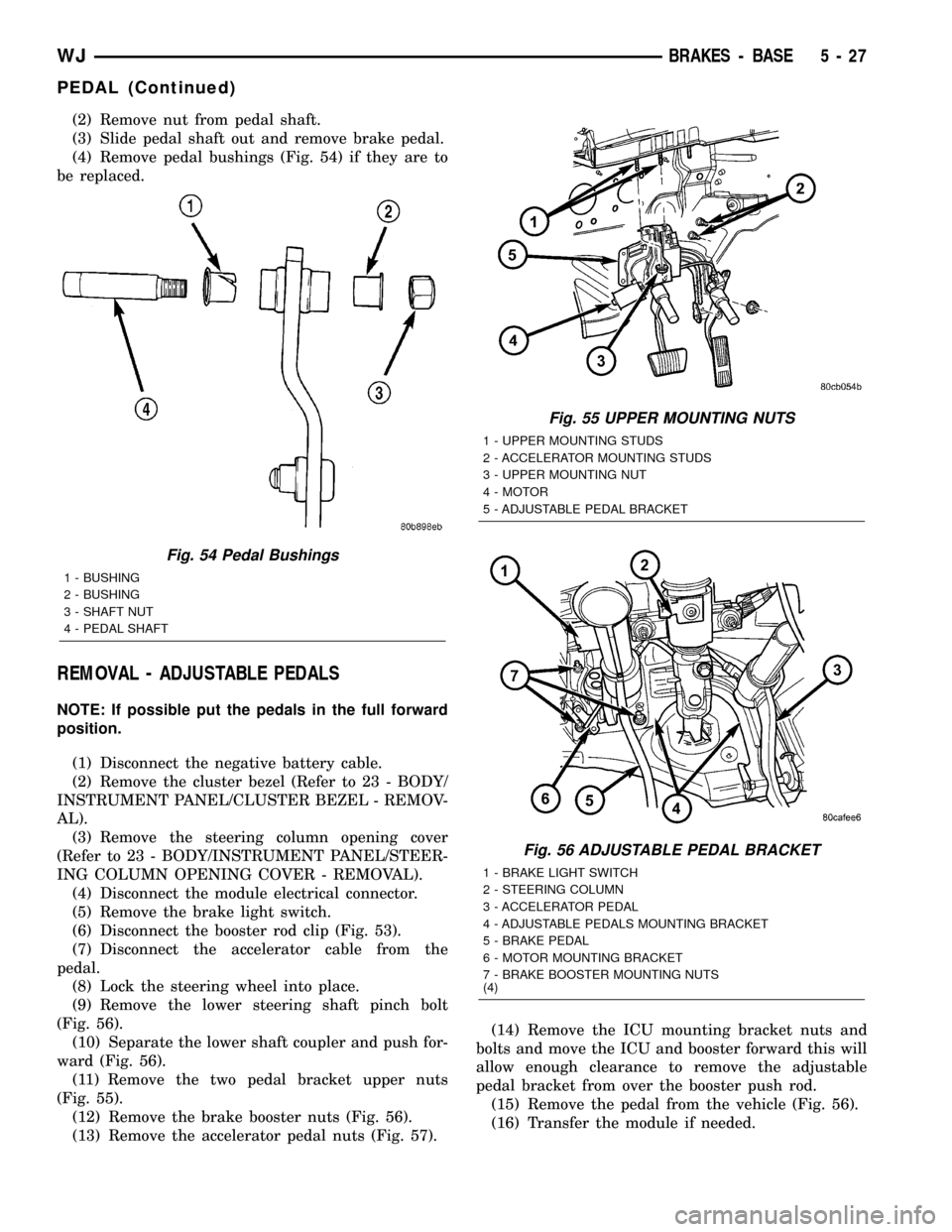
(2) Remove nut from pedal shaft.
(3) Slide pedal shaft out and remove brake pedal.
(4) Remove pedal bushings (Fig. 54) if they are to
be replaced.
REMOVAL - ADJUSTABLE PEDALS
NOTE: If possible put the pedals in the full forward
position.
(1) Disconnect the negative battery cable.
(2) Remove the cluster bezel (Refer to 23 - BODY/
INSTRUMENT PANEL/CLUSTER BEZEL - REMOV-
AL).
(3) Remove the steering column opening cover
(Refer to 23 - BODY/INSTRUMENT PANEL/STEER-
ING COLUMN OPENING COVER - REMOVAL).
(4) Disconnect the module electrical connector.
(5) Remove the brake light switch.
(6) Disconnect the booster rod clip (Fig. 53).
(7) Disconnect the accelerator cable from the
pedal.
(8) Lock the steering wheel into place.
(9) Remove the lower steering shaft pinch bolt
(Fig. 56).
(10) Separate the lower shaft coupler and push for-
ward (Fig. 56).
(11) Remove the two pedal bracket upper nuts
(Fig. 55).
(12) Remove the brake booster nuts (Fig. 56).
(13) Remove the accelerator pedal nuts (Fig. 57).(14) Remove the ICU mounting bracket nuts and
bolts and move the ICU and booster forward this will
allow enough clearance to remove the adjustable
pedal bracket from over the booster push rod.
(15) Remove the pedal from the vehicle (Fig. 56).
(16) Transfer the module if needed.
Fig. 54 Pedal Bushings
1 - BUSHING
2 - BUSHING
3 - SHAFT NUT
4 - PEDAL SHAFT
Fig. 55 UPPER MOUNTING NUTS
1 - UPPER MOUNTING STUDS
2 - ACCELERATOR MOUNTING STUDS
3 - UPPER MOUNTING NUT
4 - MOTOR
5 - ADJUSTABLE PEDAL BRACKET
Fig. 56 ADJUSTABLE PEDAL BRACKET
1 - BRAKE LIGHT SWITCH
2 - STEERING COLUMN
3 - ACCELERATOR PEDAL
4 - ADJUSTABLE PEDALS MOUNTING BRACKET
5 - BRAKE PEDAL
6 - MOTOR MOUNTING BRACKET
7 - BRAKE BOOSTER MOUNTING NUTS
(4)
WJBRAKES - BASE 5 - 27
PEDAL (Continued)
Page 203 of 2199
INSTALLATION
INSTALLATION - NON-ADJUSTABLE PEDAL
(1) Lubricate bushings, pedal shaft and pedal pin
with Mopar multi-mileage grease.
(2) Install bushings into pedal.
(3) Position pedal in bracket and install pedal
shaft in support and through pedal.
(4) Install new nut on pedal shaft and tighten to
27 N´m (20 ft. lbs.).
NOTE: Pedal shaft nut should not be reused.
(5) Install booster push rod on pedal pin and
install retainer clip on pedal pin.
(6) Check and adjust stop lamp switch if necessary.
INSTALLATION - ADJUSTABLE PEDALS
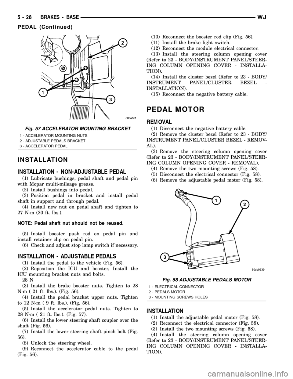
(1) Install the pedal to the vehicle (Fig. 56).
(2) Reposition the ICU and booster, Install the
ICU mounting bracket nuts and bolts.
28 N
(3) Install the brake booster nuts. Tighten to 28
N´m ( 21 ft. lbs.). (Fig. 56).
(4) Install the pedal bracket upper nuts. Tighten
to 12 N´m ( 9 ft. lbs.). (Fig. 56).
(5) Install the accelerator pedal nuts. Tighten to
28 N´m ( 21 ft. lbs.). (Fig. 57).
(6) Install the lower steering shaft coupler over the
shaft (Fig. 56).
(7) Install the lower steering shaft pinch bolt (Fig.
56).
(8) Unlock the steering wheel.
(9) Reconnect the accelerator cable to the pedal
(Fig. 56).(10) Reconnect the booster rod clip (Fig. 56).
(11) Install the brake light switch.
(12) Reconnect the module electrical connector.
(13) Install the steering column opening cover
(Refer to 23 - BODY/INSTRUMENT PANEL/STEER-
ING COLUMN OPENING COVER - INSTALLA-
TION).
(14) Install the cluster bezel (Refer to 23 - BODY/
INSTRUMENT PANEL/CLUSTER BEZEL -
INSTALLATION).
(15) Reconnect the negative battery cable.
PEDAL MOTOR
REMOVAL
(1) Disconnect the negative battery cable.
(2) Remove the cluster bezel (Refer to 23 - BODY/
INSTRUMENT PANEL/CLUSTER BEZEL - REMOV-
AL).
(3) Remove the steering column opening cover
(Refer to 23 - BODY/INSTRUMENT PANEL/STEER-
ING COLUMN OPENING COVER - REMOVAL).
(4) Remove the two mounting screws (Fig. 58).
(5) Disconnect the electrical connector (Fig. 58).
(6) Remove the adjustable pedal motor (Fig. 58).
INSTALLATION
(1) Install the adjustable pedal motor (Fig. 58).
(2) Reconnect the electrical connector (Fig. 58).
(3) Install the two mounting screws (Fig. 58).
(4) Install the steering column opening cover
(Refer to 23 - BODY/INSTRUMENT PANEL/STEER-
ING COLUMN OPENING COVER - INSTALLA-
TION).
Fig. 57 ACCELERATOR MOUNTING BRACKET
1 - ACCELERATOR MOUNTING NUTS
2 - ADJUSTABLE PEDALS BRACKET
3 - ACCELERATOR PEDAL
Fig. 58 ADJUSTABLE PEDALS MOTOR
1 - ELECTRICAL CONNECTOR
2 - PEDALS MOTOR
3 - MOUNTING SCREWS HOLES
5 - 28 BRAKES - BASEWJ
PEDAL (Continued)