2003 JEEP GRAND CHEROKEE Bolts
[x] Cancel search: BoltsPage 141 of 2199
(3) Remove the wheels and tires.
(4) Remove brake calipers and rotors.
(5) Disconnect parking brake cables from brackets
and lever.
(6) Remove wheel speed sensors.
(7) Remove brake hose at the axle junction block.
Do not disconnect the brake hydraulic lines at the
calipers.
(8) Disconnect the vent hose from the axle shaft
tube.
(9) Mark propeller shaft and yokes for installation
reference.
(10) Remove propeller shaft.
(11) Disconnect stabilizer bar links.
(12) Remove upper suspension arm rear axle ball
joint nut.
(13) Separate rear axle ball joint from the upper
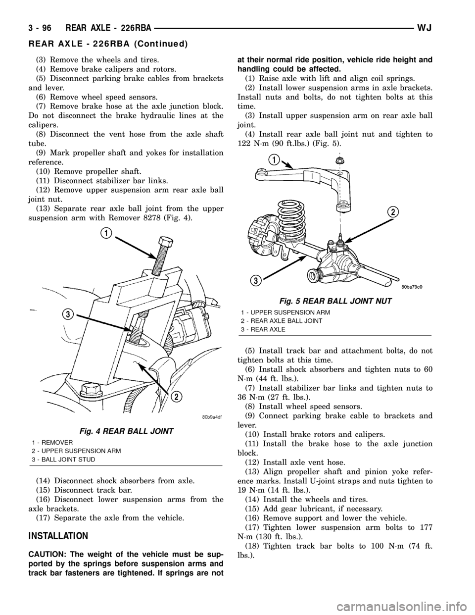
suspension arm with Remover 8278 (Fig. 4).
(14) Disconnect shock absorbers from axle.
(15) Disconnect track bar.
(16) Disconnect lower suspension arms from the
axle brackets.
(17) Separate the axle from the vehicle.
INSTALLATION
CAUTION: The weight of the vehicle must be sup-
ported by the springs before suspension arms and
track bar fasteners are tightened. If springs are notat their normal ride position, vehicle ride height and
handling could be affected.
(1) Raise axle with lift and align coil springs.
(2) Install lower suspension arms in axle brackets.
Install nuts and bolts, do not tighten bolts at this
time.
(3) Install upper suspension arm on rear axle ball
joint.
(4) Install rear axle ball joint nut and tighten to
122 N´m (90 ft.lbs.) (Fig. 5).
(5) Install track bar and attachment bolts, do not
tighten bolts at this time.
(6) Install shock absorbers and tighten nuts to 60
N´m (44 ft. lbs.).
(7) Install stabilizer bar links and tighten nuts to
36 N´m (27 ft. lbs.).
(8) Install wheel speed sensors.
(9) Connect parking brake cable to brackets and
lever.
(10) Install brake rotors and calipers.
(11) Install the brake hose to the axle junction
block.
(12) Install axle vent hose.
(13) Align propeller shaft and pinion yoke refer-
ence marks. Install U-joint straps and nuts tighten to
19 N´m (14 ft. lbs.).
(14) Install the wheels and tires.
(15) Add gear lubricant, if necessary.
(16) Remove support and lower the vehicle.
(17) Tighten lower suspension arm bolts to 177
N´m (130 ft. lbs.).
(18) Tighten track bar bolts to 100 N´m (74 ft.
lbs.).
Fig. 4 REAR BALL JOINT
1 - REMOVER
2 - UPPER SUSPENSION ARM
3 - BALL JOINT STUD
Fig. 5 REAR BALL JOINT NUT
1 - UPPER SUSPENSION ARM
2 - REAR AXLE BALL JOINT
3 - REAR AXLE
3 - 96 REAR AXLE - 226RBAWJ
REAR AXLE - 226RBA (Continued)
Page 143 of 2199

PINION GEAR DEPTH VARIANCE
Original Pinion
Gear Depth
VarianceReplacement Pinion Gear Depth Variance
24232221 0 +1 +2 +3 +4
+4+0.008 +0.007 +0.006 +0.005 +0.004 +0.003 +0.002 +0.001 0
+3+0.007 +0.006 +0.005 +0.004 +0.003 +0.002 +0.001 020.001
+2+0.006 +0.005 +0.004 +0.003 +0.002 +0.001 020.00120.002
+1+0.005 +0.004 +0.003 +0.002 +0.001 020.00120.00220.003
0+0.004 +0.003 +0.002 +0.001 020.00120.00220.00320.004
21+0.003 +0.002 +0.001 020.00120.00220.00320.00420.005
22+0.002 +0.001 020.00120.00220.00320.00420.00520.006
23+0.001 020.00120.00220.00320.00420.00520.00620.007
24020.00120.00220.00320.00420.00520.00620.00720.008
PINION DEPTH MEASUREMENT
Measurements are taken with pinion bearing cups
and pinion bearings installed in the housing. Take
measurements with Pinion Gauge Set 6775 and Dial
Indicator C-3339 (Fig. 8).(1) Assemble Pinion Height Block 6739, Pinion
Block 8144 and rear pinion bearing onto Screw 6741
(Fig. 8).
(2) Insert assembled height gauge components,
rear bearing and screw into the housing through pin-
ion bearing cups (Fig. 9).
(3) Install front pinion bearing and Cone-nut 6740
hand tight (Fig. 8).
(4) Place Arbor Disc 6927A on Arbor D-115-3 in
position in the housing side bearing cradles (Fig. 10).
Install differential bearing caps in their original posi-
tions on arbor discs and tighten cap bolts to 85 N´m
(63 ft. lbs.).
Fig. 8 PINION GEAR DEPTH GAUGE
1 - DIAL INDICATOR
2 - ARBOR
3 - PINION HEIGHT BLOCK
4 - CONE
5 - SCREW
6 - PINION BLOCK
7 - SCOOTER BLOCK
8 - ARBOR DISC
Fig. 9 PINION HEIGHT BLOCK
1 - PINION BLOCK
2 - PINION HEIGHT BLOCK
3 - 98 REAR AXLE - 226RBAWJ
REAR AXLE - 226RBA (Continued)
Page 145 of 2199
(2) Install ring gear on differential case and
tighten bolts to specification.
(3)
Install Dummy Bearings 6929-A on differential case.
(4) Install differential case in the housing.
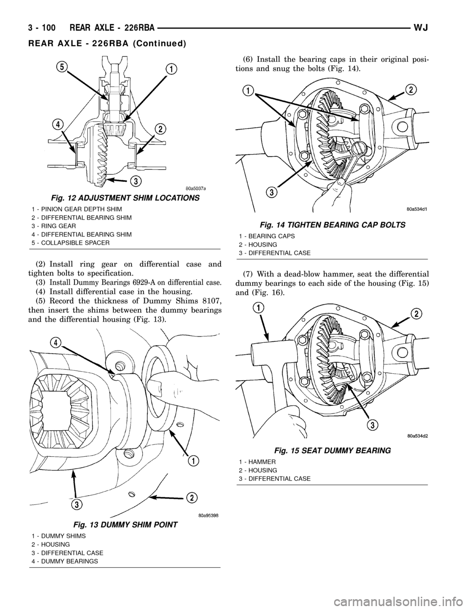
(5) Record the thickness of Dummy Shims 8107,
then insert the shims between the dummy bearings
and the differential housing (Fig. 13).(6) Install the bearing caps in their original posi-
tions and snug the bolts (Fig. 14).
(7) With a dead-blow hammer, seat the differential
dummy bearings to each side of the housing (Fig. 15)
and (Fig. 16).
Fig. 12 ADJUSTMENT SHIM LOCATIONS
1 - PINION GEAR DEPTH SHIM
2 - DIFFERENTIAL BEARING SHIM
3 - RING GEAR
4 - DIFFERENTIAL BEARING SHIM
5 - COLLAPSIBLE SPACER
Fig. 13 DUMMY SHIM POINT
1 - DUMMY SHIMS
2 - HOUSING
3 - DIFFERENTIAL CASE
4 - DUMMY BEARINGS
Fig. 14 TIGHTEN BEARING CAP BOLTS
1 - BEARING CAPS
2 - HOUSING
3 - DIFFERENTIAL CASE
Fig. 15 SEAT DUMMY BEARING
1 - HAMMER
2 - HOUSING
3 - DIFFERENTIAL CASE
3 - 100 REAR AXLE - 226RBAWJ
REAR AXLE - 226RBA (Continued)
Page 146 of 2199
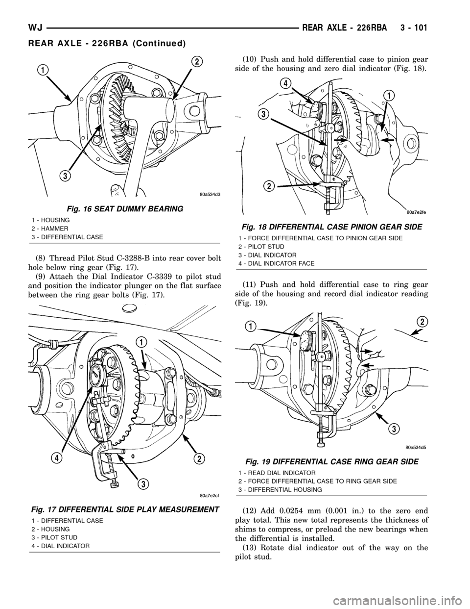
(8) Thread Pilot Stud C-3288-B into rear cover bolt
hole below ring gear (Fig. 17).
(9) Attach the Dial Indicator C-3339 to pilot stud
and position the indicator plunger on the flat surface
between the ring gear bolts (Fig. 17).(10) Push and hold differential case to pinion gear
side of the housing and zero dial indicator (Fig. 18).
(11) Push and hold differential case to ring gear
side of the housing and record dial indicator reading
(Fig. 19).
(12) Add 0.0254 mm (0.001 in.) to the zero end
play total. This new total represents the thickness of
shims to compress, or preload the new bearings when
the differential is installed.
(13) Rotate dial indicator out of the way on the
pilot stud.
Fig. 16 SEAT DUMMY BEARING
1 - HOUSING
2 - HAMMER
3 - DIFFERENTIAL CASE
Fig. 17 DIFFERENTIAL SIDE PLAY MEASUREMENT
1 - DIFFERENTIAL CASE
2 - HOUSING
3 - PILOT STUD
4 - DIAL INDICATOR
Fig. 18 DIFFERENTIAL CASE PINION GEAR SIDE
1 - FORCE DIFFERENTIAL CASE TO PINION GEAR SIDE
2 - PILOT STUD
3 - DIAL INDICATOR
4 - DIAL INDICATOR FACE
Fig. 19 DIFFERENTIAL CASE RING GEAR SIDE
1 - READ DIAL INDICATOR
2 - FORCE DIFFERENTIAL CASE TO RING GEAR SIDE
3 - DIFFERENTIAL HOUSING
WJREAR AXLE - 226RBA 3 - 101
REAR AXLE - 226RBA (Continued)
Page 147 of 2199
(14) Remove differential case and dummy bearings
from the housing.
(15) Install the pinion gear in the housing. Install
the pinion yoke and establish the correct pinion
rotating torque.
(16) Install differential case and Dummy Bearings
6929-A in the housing.
(17) Install a single dummy shim in the ring gear
side. Install bearing caps and tighten bolts snug.
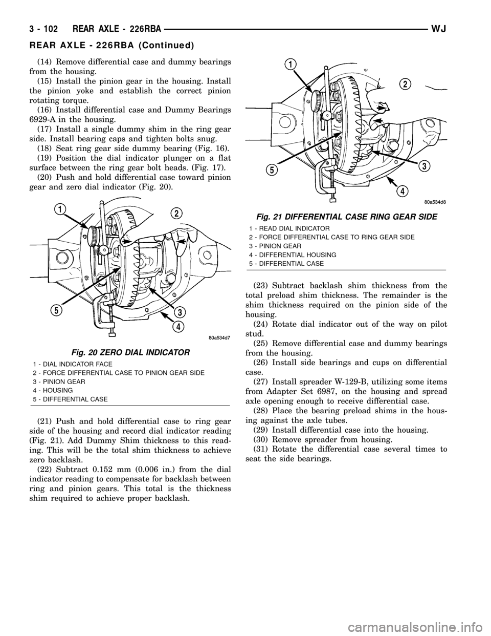
(18) Seat ring gear side dummy bearing (Fig. 16).
(19) Position the dial indicator plunger on a flat
surface between the ring gear bolt heads. (Fig. 17).
(20) Push and hold differential case toward pinion
gear and zero dial indicator (Fig. 20).
(21) Push and hold differential case to ring gear
side of the housing and record dial indicator reading
(Fig. 21). Add Dummy Shim thickness to this read-
ing. This will be the total shim thickness to achieve
zero backlash.
(22) Subtract 0.152 mm (0.006 in.) from the dial
indicator reading to compensate for backlash between
ring and pinion gears. This total is the thickness
shim required to achieve proper backlash.(23) Subtract backlash shim thickness from the
total preload shim thickness. The remainder is the
shim thickness required on the pinion side of the
housing.
(24) Rotate dial indicator out of the way on pilot
stud.
(25) Remove differential case and dummy bearings
from the housing.
(26) Install side bearings and cups on differential
case.
(27) Install spreader W-129-B, utilizing some items
from Adapter Set 6987, on the housing and spread
axle opening enough to receive differential case.
(28) Place the bearing preload shims in the hous-
ing against the axle tubes.
(29) Install differential case into the housing.
(30) Remove spreader from housing.
(31) Rotate the differential case several times to
seat the side bearings.
Fig. 20 ZERO DIAL INDICATOR
1 - DIAL INDICATOR FACE
2 - FORCE DIFFERENTIAL CASE TO PINION GEAR SIDE
3 - PINION GEAR
4 - HOUSING
5 - DIFFERENTIAL CASE
Fig. 21 DIFFERENTIAL CASE RING GEAR SIDE
1 - READ DIAL INDICATOR
2 - FORCE DIFFERENTIAL CASE TO RING GEAR SIDE
3 - PINION GEAR
4 - DIFFERENTIAL HOUSING
5 - DIFFERENTIAL CASE
3 - 102 REAR AXLE - 226RBAWJ
REAR AXLE - 226RBA (Continued)
Page 150 of 2199
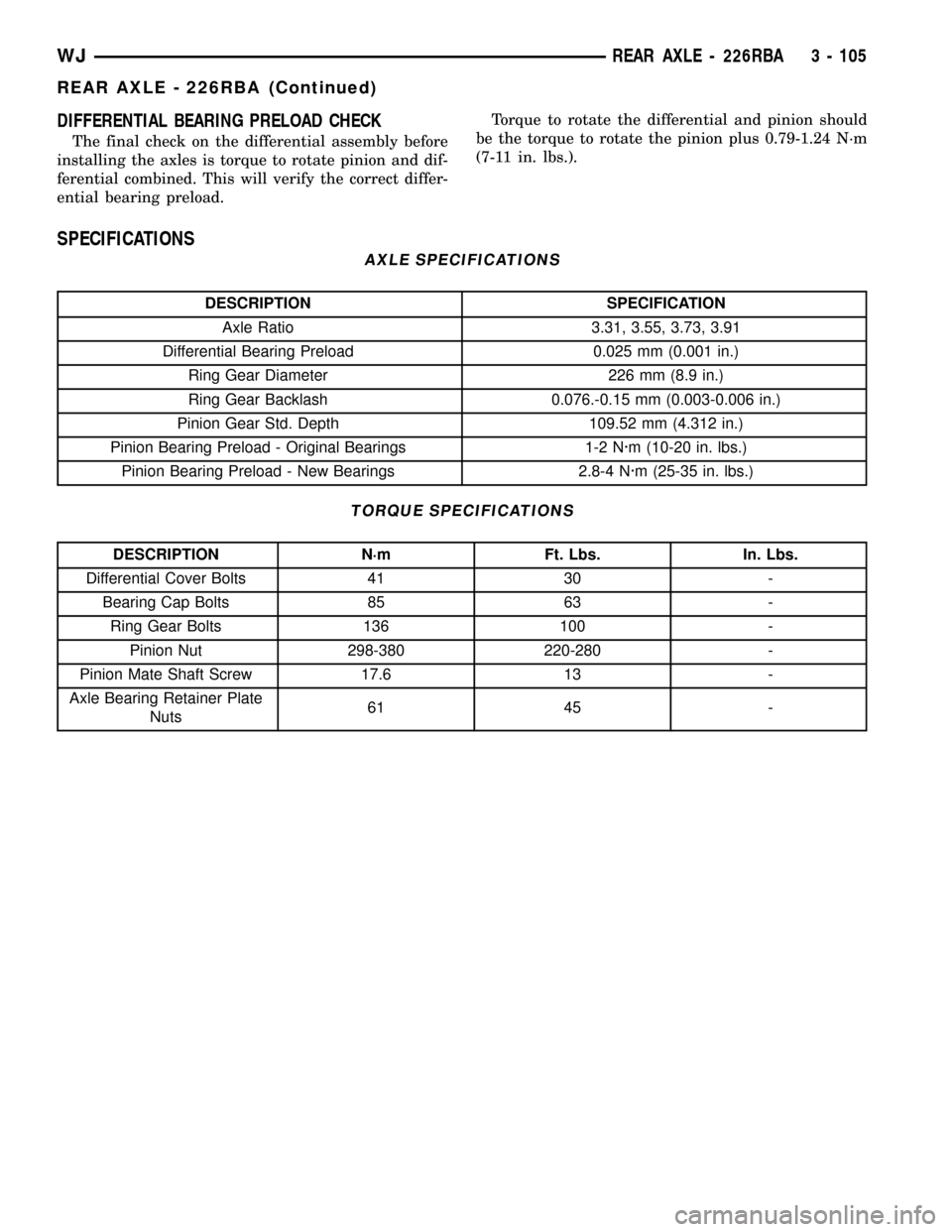
DIFFERENTIAL BEARING PRELOAD CHECK
The final check on the differential assembly before
installing the axles is torque to rotate pinion and dif-
ferential combined. This will verify the correct differ-
ential bearing preload.Torque to rotate the differential and pinion should
be the torque to rotate the pinion plus 0.79-1.24 N´m
(7-11 in. lbs.).
SPECIFICATIONS
AXLE SPECIFICATIONS
DESCRIPTION SPECIFICATION
Axle Ratio 3.31, 3.55, 3.73, 3.91
Differential Bearing Preload 0.025 mm (0.001 in.)
Ring Gear Diameter 226 mm (8.9 in.)
Ring Gear Backlash 0.076.-0.15 mm (0.003-0.006 in.)
Pinion Gear Std. Depth 109.52 mm (4.312 in.)
Pinion Bearing Preload - Original Bearings 1-2 N´m (10-20 in. lbs.)
Pinion Bearing Preload - New Bearings 2.8-4 N´m (25-35 in. lbs.)
TORQUE SPECIFICATIONS
DESCRIPTION N´m Ft. Lbs. In. Lbs.
Differential Cover Bolts 41 30 -
Bearing Cap Bolts 85 63 -
Ring Gear Bolts 136 100 -
Pinion Nut 298-380 220-280 -
Pinion Mate Shaft Screw 17.6 13 -
Axle Bearing Retainer Plate
Nuts61 45 -
WJREAR AXLE - 226RBA 3 - 105
REAR AXLE - 226RBA (Continued)
Page 160 of 2199

NOTE: If more than 380 N´m (280 ft. lbs.) torque is
required to crush the collapsible spacer, the spacer
is defective and must be replaced.
(7) Check rotating torque with an inch pound
torque wrench (Fig. 44). The rotating torque of the
pinion gear should be, the reading recorded during
removal plus an additional 0.56 N´m (5 in. lbs.).
(8)
Install propeller shaft with reference marks align.
(9) Install rear brake rotors and calipers.
(10) Add gear lubricant, if necessary.
(11) Install wheel and tire assemblies.
(12) Remove supports and lower vehicle.
DIFFERENTIAL
REMOVAL
(1) Raise and support vehicle.
(2) Remove fill hole plug from the differential
housing cover.
(3) Remove differential housing cover and drain
fluid.
(4) Clean the housing cavity with flushing oil, light
engine oil or lint free cloth.
NOTE: Do not use water, steam, kerosene or gaso-
line for cleaning.
(5) Remove axle shafts.(6)
Note the reference letters stamped on the bearing
caps and housing machined sealing surface (Fig. 45).
(7) Loosen the differential bearing cap bolts.
(8) Position Spreader W-129-B with Adapter Kit
6987B on differential locating holes (Fig. 46). Install
holddown clamps and tighten the turnbuckle finger-
tight.
Fig. 44 PINION ROTATING TORQUE
1 - TORQUE WRENCH
2 - PINION YOKE
Fig. 45 BEARING CAP REFERENCE
1 - REFERENCE LETTERS
2 - REFERENCE LETTERS
Fig. 46 SPREADER LOCATION
1 - DIFFERENTIAL HOUSING
2 - DOWEL
3 - SAFETY HOLD DOWN
4 - SPREADER
5 - TURNBUCKLE
WJREAR AXLE - 226RBA 3 - 115
COLLAPSIBLE SPACER (Continued)
Page 161 of 2199

(9) Install a Pilot Stud C-3288-B at the left side of
the differential housing. Attach Dial Indicator C-3339
to pilot stud. Load the indicator plunger against the
opposite side of the housing (Fig. 47) and zero the
indicator.
CAUTION: Never spread the housing over 0.38 mm
(0.015 in). If housing is over-spread, it could dis-
torted and damaged the housing.
(10) Spread housing enough to remove the differ-
ential case from the housing. Measure the distance
with the dial indicator (Fig. 48).
(11) Remove the dial indicator.
(12) While holding the differential case in position,
remove the differential bearing cap bolts and caps.
(13) Remove differential from the housing and tag
differential bearing cups to indicate location (Fig. 49).
(14) Remove spreader from housing.
Fig. 47 DIAL INDICATOR LOCATION
1 - CLAMP
2 - DIAL INDICATOR
3 - LEVER ADAPTER
4 - SPREADER
5 - PILOT STUD
Fig. 48 SPREAD DIFFERENTIAL HOUSING
1 - DIAL INDICATOR
2 - SPREADER
Fig. 49 DIFFERENTIAL CASE REMOVAL
1 - DIFFERENTIAL HOUSING
2 - DIFFERENTIAL CASE
3 - BEARING CUPS
3 - 116 REAR AXLE - 226RBAWJ
DIFFERENTIAL (Continued)