2003 JEEP GRAND CHEROKEE mirror
[x] Cancel search: mirrorPage 1875 of 2199
leak area. If the hose cannot be positioned without
being held, have someone help do the water test.
Some water leaks must be tested for a considerable
length of time to become apparent. When a leak
appears, find the highest point of the water track or
drop. The highest point usually will show the point of
entry. After leak point has been found, repair the
leak and water test to verify that the leak has
stopped.
Locating the entry point of water that is leaking
into a cavity between panels can be difficult. The
trapped water may splash or run from the cavity,
often at a distance from the entry point. Most water
leaks of this type become apparent after accelerating,
stopping, turning, or when on an incline.
MIRROR INSPECTION METHOD
When a leak point area is visually obstructed, use
a suitable mirror to gain visual access. A mirror can
also be used to deflect light to a limited-access area
to assist in locating a leak point.
BRIGHT LIGHT LEAK TEST METHOD
Some water leaks in the luggage compartment can
be detected without water testing. Position the vehi-
cle in a brightly lit area. From inside the darkened
luggage compartment inspect around seals and body
seams. If necessary, have a helper direct a drop light
over the suspected leak areas around the luggage
compartment. If light is visible through a normally
sealed location, water could enter through the open-
ing.
PRESSURIZED LEAK TEST METHOD
When a water leak into the passenger compart-
ment cannot be detected by water testing, pressurize
the passenger compartment and soap test exterior of
the vehicle. To pressurize the passenger compart-
ment, close all doors and windows, start engine, and
set heater control to high blower in HEAT position. If
engine can not be started, connect a charger to the
battery to ensure adequate voltage to the blower.
With interior pressurized, apply dish detergent solu-
tion to suspected leak area on the exterior of the
vehicle. Apply detergent solution with spray device or
soft bristle brush. If soap bubbles occur at a body
seam, joint, seal or gasket, the leak entry point could
be at that location.
WIND NOISE
Wind noise is the result of most air leaks. Air leaks
can be caused by poor sealing, improper body compo-
nent alignment, body seam porosity, or missing plugs
in the engine compartment or door hinge pillar areas.
All body sealing points should be airtight in normal
driving conditions. Moving sealing surfaces will notalways seal airtight under all conditions. At times,
side glass or door seals will allow wind noise to be
noticed in the passenger compartment during high
cross winds. Over compensating on door or glass
adjustments to stop wind noise that occurs under
severe conditions can cause premature seal wear and
excessive closing or latching effort. After a repair pro-
cedure has been performed, test vehicle to verify
noise has stopped before returning vehicle to use.
Wind noise can also be caused by improperly fitted
exterior moldings or body ornamentation. Loose
moldings can flutter, creating a buzzing or chattering
noise. An open cavity or protruding edge can create a
whistling or howling noise. Inspect the exterior of the
vehicle to verify that these conditions do not exist.
VISUAL INSPECTION BEFORE TESTS
Verify that floor and body plugs are in place and
body components are aligned and sealed. If compo-
nent alignment or sealing is necessary, refer to the
appropriate section of this group for proper proce-
dures.
ROAD TESTING WIND NOISE
(1) Drive the vehicle to verify the general location
of the wind noise.
(2) Apply 50 mm (2 in.) masking tape in 150 mm
(6 in.) lengths along weatherstrips, weld seams or
moldings. After each length is applied, drive the vehi-
cle. If noise goes away after a piece of tape is applied,
remove tape, locate, and repair defect.
POSSIBLE CAUSE OF WIND NOISE
²Moldings standing away from body surface can
catch wind and whistle.
²Gaps in sealed areas behind overhanging body
flanges can cause wind-rushing sounds.
²Misaligned movable components.
²Missing or improperly installed plugs in pillars.
²Weld burn through holes.
STANDARD PROCEDURE
STANDARD PROCEDURE - BODY LUBRICATION
All mechanisms and linkages should be lubricated
when necessary. This will maintain ease of operation
and provide protection against rust and excessive
wear. The weatherstrip seals should be lubricated to
prolong their life as well as to improve door sealing.
All applicable exterior and interior vehicle operat-
ing mechanisms should be inspected and cleaned.
Pivot/sliding contact areas on the mechanisms should
then be lubricated.
(1) When necessary, lubricate the operating mech-
anisms with the specified lubricants.
23 - 2 BODYWJ
BODY (Continued)
Page 1890 of 2199
INSTALLATION
(1) Connect lock cylinder switch, if equipped.
(2) Position lock cylinder in door handle.
(3) Position lock cylinder retainer and install
screw (Fig. 13).
(4) Install outside door handle, refer to (Refer to
23 - BODY/DOOR - FRONT/EXTERIOR HANDLE -
INSTALLATION).
TRIM PANEL
REMOVAL
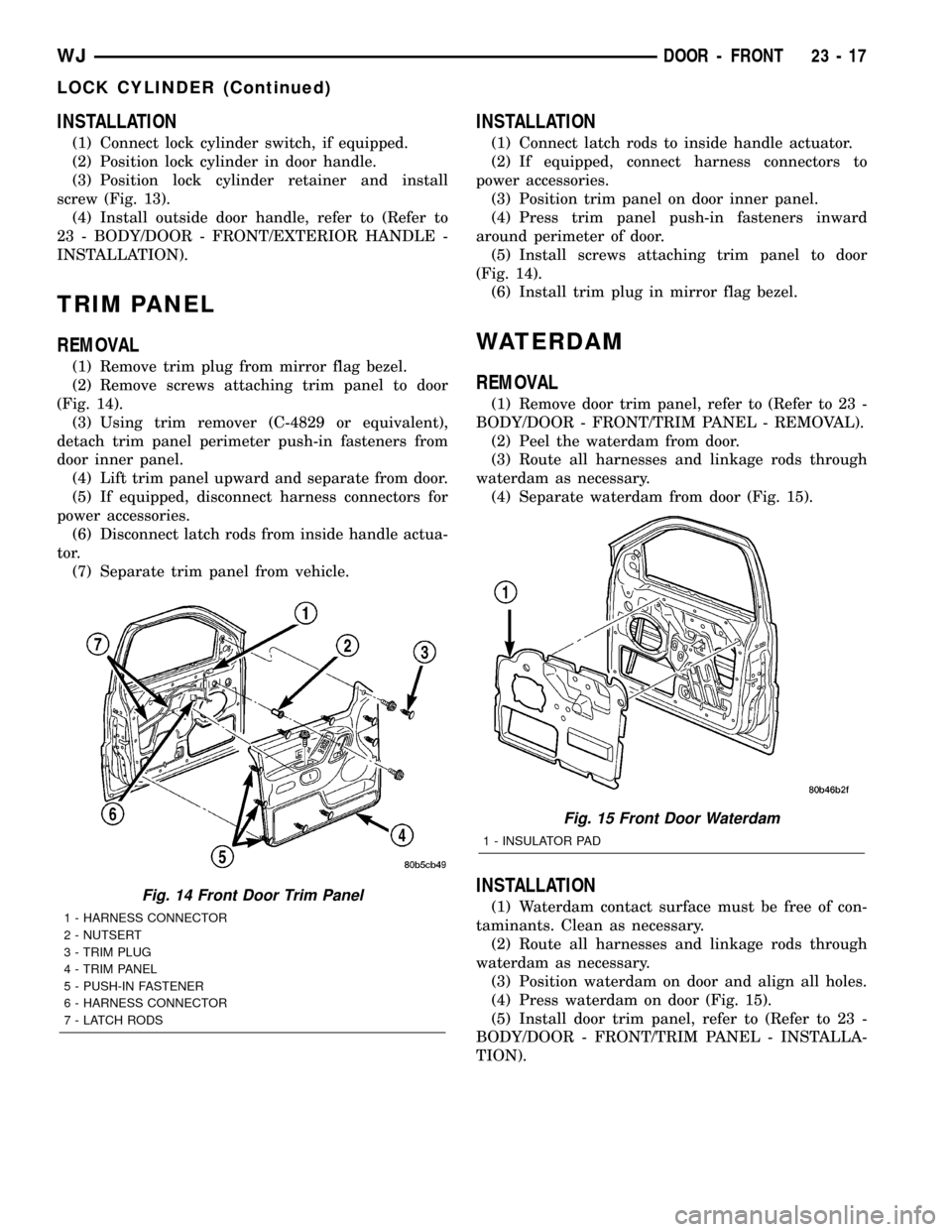
(1) Remove trim plug from mirror flag bezel.
(2) Remove screws attaching trim panel to door
(Fig. 14).
(3) Using trim remover (C-4829 or equivalent),
detach trim panel perimeter push-in fasteners from
door inner panel.
(4) Lift trim panel upward and separate from door.
(5) If equipped, disconnect harness connectors for
power accessories.
(6) Disconnect latch rods from inside handle actua-
tor.
(7) Separate trim panel from vehicle.
INSTALLATION
(1) Connect latch rods to inside handle actuator.
(2) If equipped, connect harness connectors to
power accessories.
(3) Position trim panel on door inner panel.
(4) Press trim panel push-in fasteners inward
around perimeter of door.
(5) Install screws attaching trim panel to door
(Fig. 14).
(6) Install trim plug in mirror flag bezel.
WATERDAM
REMOVAL
(1) Remove door trim panel, refer to (Refer to 23 -
BODY/DOOR - FRONT/TRIM PANEL - REMOVAL).
(2) Peel the waterdam from door.
(3) Route all harnesses and linkage rods through
waterdam as necessary.
(4) Separate waterdam from door (Fig. 15).
INSTALLATION
(1) Waterdam contact surface must be free of con-
taminants. Clean as necessary.
(2) Route all harnesses and linkage rods through
waterdam as necessary.
(3) Position waterdam on door and align all holes.
(4) Press waterdam on door (Fig. 15).
(5) Install door trim panel, refer to (Refer to 23 -
BODY/DOOR - FRONT/TRIM PANEL - INSTALLA-
TION).Fig. 14 Front Door Trim Panel
1 - HARNESS CONNECTOR
2 - NUTSERT
3 - TRIM PLUG
4 - TRIM PANEL
5 - PUSH-IN FASTENER
6 - HARNESS CONNECTOR
7 - LATCH RODS
Fig. 15 Front Door Waterdam
1 - INSULATOR PAD
WJDOOR - FRONT 23 - 17
LOCK CYLINDER (Continued)
Page 1898 of 2199
EXTERIOR
TABLE OF CONTENTS
page page
BODY SIDE MOLDINGS
REMOVAL
REMOVAL±FRONT DOOR...............25
REMOVAL±REAR DOOR................26
REMOVAL±FENDER/QUARTER PANEL.....26
INSTALLATION
INSTALLATION±FRONT DOOR...........26
INSTALLATION±REAR DOOR............26
INSTALLATION±FENDER/QUARTER PANEL . 26
COWL GRILLE
REMOVAL.............................27
INSTALLATION.........................27
D-PILLAR APPLIQUE
REMOVAL.............................27
INSTALLATION.........................27
D-PILLAR AIR EXHAUSTER
REMOVAL.............................27
INSTALLATION.........................27
AIR EXHAUSTER
REMOVAL.............................27
INSTALLATION.........................27
EXTERIOR NAME PLATES
REMOVAL.............................28
INSTALLATION.........................28FRONT FENDER
REMOVAL.............................28
INSTALLATION.........................29
FUEL FILL DOOR
REMOVAL.............................29
INSTALLATION.........................29
GRILLE
REMOVAL.............................29
INSTALLATION.........................29
HEADLAMP MOUNTING MODULE
REMOVAL.............................30
INSTALLATION.........................30
LUGGAGE RACK
REMOVAL.............................30
INSTALLATION.........................31
SIDE VIEW MIRROR GLASS
REMOVAL.............................31
INSTALLATION.........................31
SIDE VIEW MIRROR
REMOVAL.............................31
INSTALLATION.........................31
ROCK RAIL
REMOVAL.............................32
INSTALLATION.........................32
BODY SIDE MOLDINGS
REMOVAL
REMOVAL±FRONT DOOR
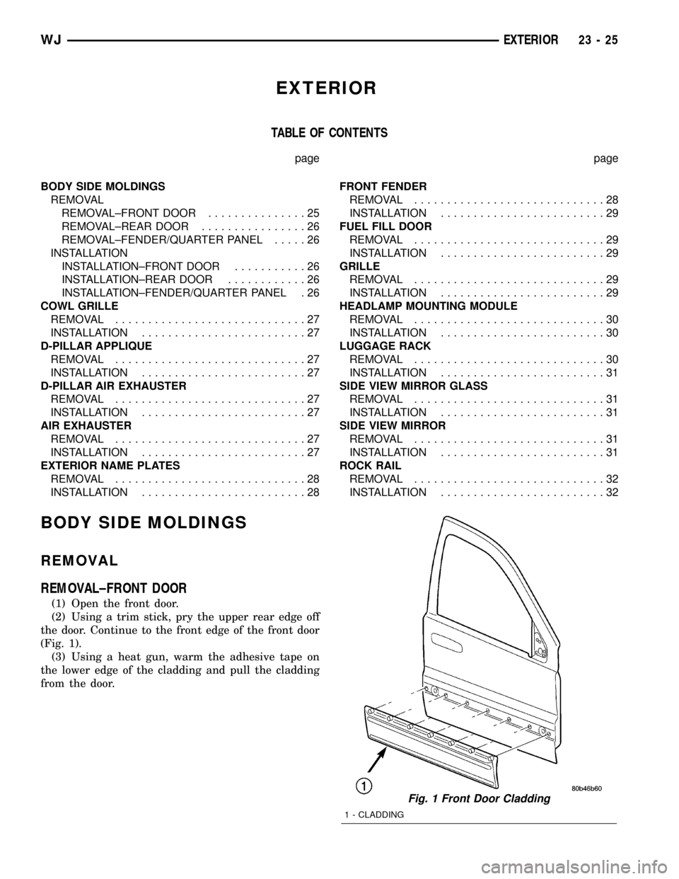
(1) Open the front door.
(2) Using a trim stick, pry the upper rear edge off
the door. Continue to the front edge of the front door
(Fig. 1).
(3) Using a heat gun, warm the adhesive tape on
the lower edge of the cladding and pull the cladding
from the door.
Fig. 1 Front Door Cladding
1 - CLADDING
WJEXTERIOR 23 - 25
Page 1904 of 2199
(4) Remove the screws attaching the supports to
the roof panel.
(5) Separate the supports from the roof panel.
NOTE: If a crossbar needs to be serviced, the for-
ward or rearward supports will have to be removed.
INSTALLATION
(1) Position the supports on the roof panel and
install the screw. Be sure that the gasket is properly
seated.
(2) Position the luggage rack on the supports.
(3) Install the screws attaching the side rails to
the supports.
(4) Position the supports covers on the supports
and press into place.
SIDE VIEW MIRROR GLASS
REMOVAL
(1) With damaged mirror still on vehicle, position
mirror glass down and centered.
(2) Position a wide leverage device between the
bottom edge of the glass and the mirror shell.
(3) Firmly apply pressure in an upward direction
until glass assembly disengages from adapter plate.
(4) Disconnect the heater wire terminal, if
equipped, or the EC plug, if equipped.
INSTALLATION
(1) Connect the heater wire terminal or the EC
plug, if equipped.
(2) Position the replacement glass in the mirror
shell and align the four snap tabs with the four cav-
ities in the shell.
(3) Apply firm pressure inward until the replace-
ment glass assembly engages with the adapter plate.
Correct assembly will result in a firm click. Glass
assembly should exhibit even gaps to the shell when
complete.
(4) Pull lightly on corners of glass assembly to
ensure all four snaps are engaged and there is no
free play.
SIDE VIEW MIRROR
REMOVAL
(1) Remove door trim panel, refer to (Refer to 23 -
BODY/DOOR - FRONT/TRIM PANEL - REMOVAL).
(2) Disengage power mirror harness connector, if
equipped.
(3) Remove mirror flag seal.
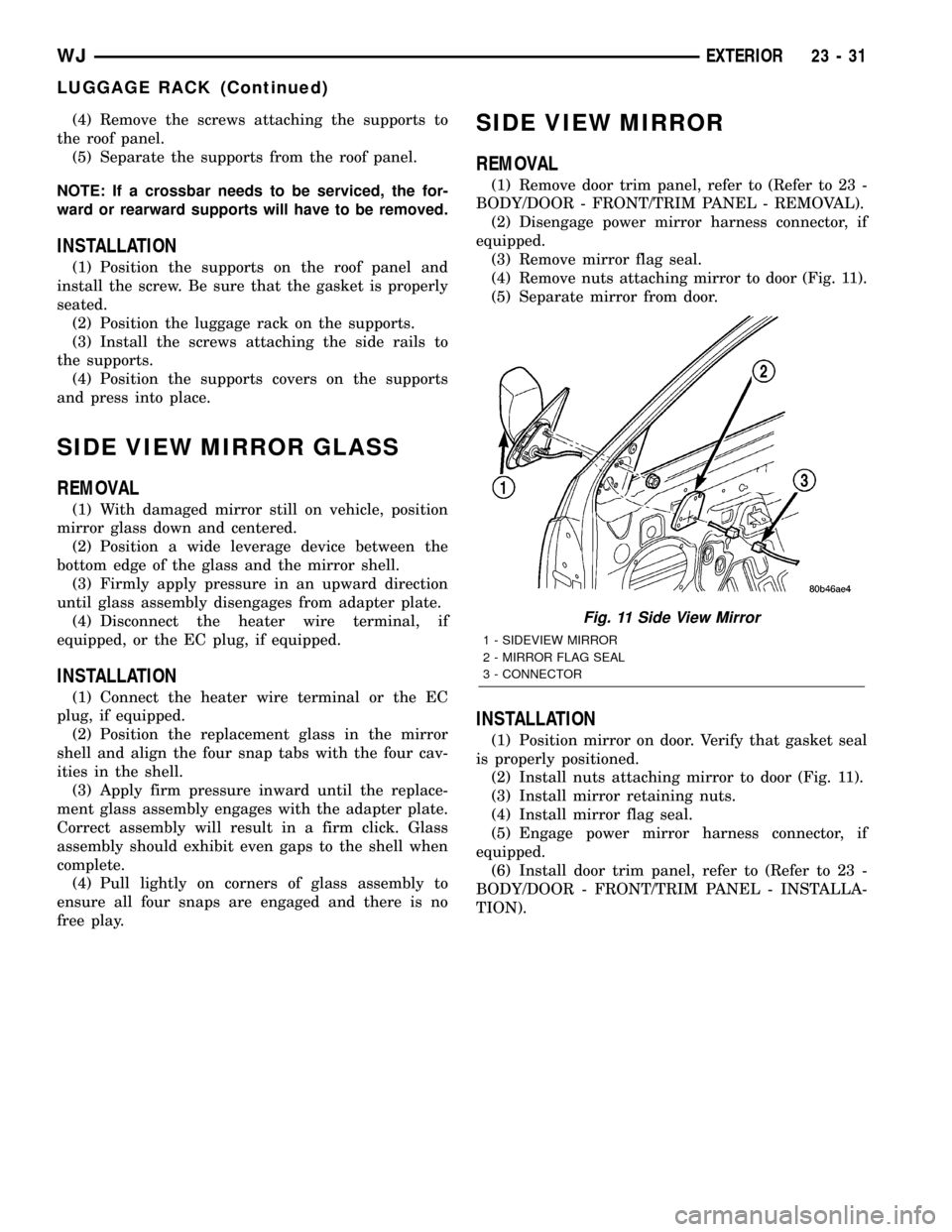
(4) Remove nuts attaching mirror to door (Fig. 11).
(5) Separate mirror from door.
INSTALLATION
(1) Position mirror on door. Verify that gasket seal
is properly positioned.
(2) Install nuts attaching mirror to door (Fig. 11).
(3) Install mirror retaining nuts.
(4) Install mirror flag seal.
(5) Engage power mirror harness connector, if
equipped.
(6) Install door trim panel, refer to (Refer to 23 -
BODY/DOOR - FRONT/TRIM PANEL - INSTALLA-
TION).
Fig. 11 Side View Mirror
1 - SIDEVIEW MIRROR
2 - MIRROR FLAG SEAL
3 - CONNECTOR
WJEXTERIOR 23 - 31
LUGGAGE RACK (Continued)
Page 1942 of 2199
INTERIOR
TABLE OF CONTENTS
page page
A-PILLAR TRIM
REMOVAL.............................69
INSTALLATION.........................69
ASSIST HANDLE
REMOVAL.............................70
INSTALLATION.........................70
B-PILLAR LOWER TRIM
REMOVAL.............................70
INSTALLATION.........................70
B-PILLAR UPPER TRIM
REMOVAL.............................71
INSTALLATION.........................71
CARPETS AND FLOOR MATS
REMOVAL
REMOVAL - FRONT CARPET............71
REMOVAL - CARGO AREA CARPET.......71
INSTALLATION
INSTALLATION - FRONT CARPET.........71
INSTALLATION - CARGO AREA CARPET . . . 72
COWL TRIM
REMOVAL.............................72
INSTALLATION.........................72
C-PILLAR TRIM
REMOVAL.............................72
INSTALLATION.........................72
DOOR SILL SCUFF PLATE
REMOVAL.............................74
INSTALLATION.........................74
DOOR SILL TRIM
REMOVAL.............................74INSTALLATION.........................74
D-PILLAR TRIM
REMOVAL.............................75
INSTALLATION.........................75
FLOOR CONSOLE
REMOVAL.............................76
INSTALLATION.........................76
HEADLINER
REMOVAL.............................77
INSTALLATION.........................77
LIFTGATE OPENING UPPER TRIM
REMOVAL.............................79
INSTALLATION.........................79
QUARTER TRIM PANEL
REMOVAL.............................79
INSTALLATION.........................79
REAR STORAGE BOX
REMOVAL.............................79
INSTALLATION.........................80
REAR VIEW MIRROR
REMOVAL.............................80
INSTALLATION
INSTALLATION.......................80
INSTALLATION - REARVIEW MIRROR
SUPPORT BRACKET...................80
SUN VISOR
REMOVAL.............................80
INSTALLATION.........................80
A-PILLAR TRIM
REMOVAL
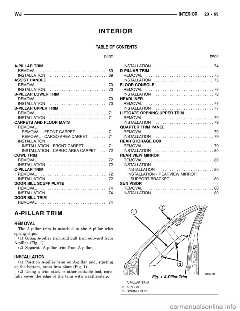
The A-pillar trim is attached to the A-pillar with
spring clips.
(1) Grasp A-pillar trim and pull trim outward from
A-pillar (Fig. 1).
(2) Separate A-pillar trim from A-pillar.
INSTALLATION
(1) Position A-pillar trim on A-pillar and, starting
at the bottom, press into place (Fig. 1).
(2) Using a trim stick or other suitable tool, care-
fully cover the edge of the trim with weatherstrip.
Fig. 1 A-Pillar Trim
1 - A-PILLAR TRIM
2 - A-PILLAR
3 - SPRING CLIP
WJINTERIOR 23 - 69
Page 1953 of 2199
INSTALLATION
(1) Position the bin hooks high in the slots on the
quarter trim panel.
(2) Push downward until the bin snaps into place.
(3) Install the hinge screws.
REAR VIEW MIRROR
REMOVAL
(1)If equipped, disconnect mirror harness connector.
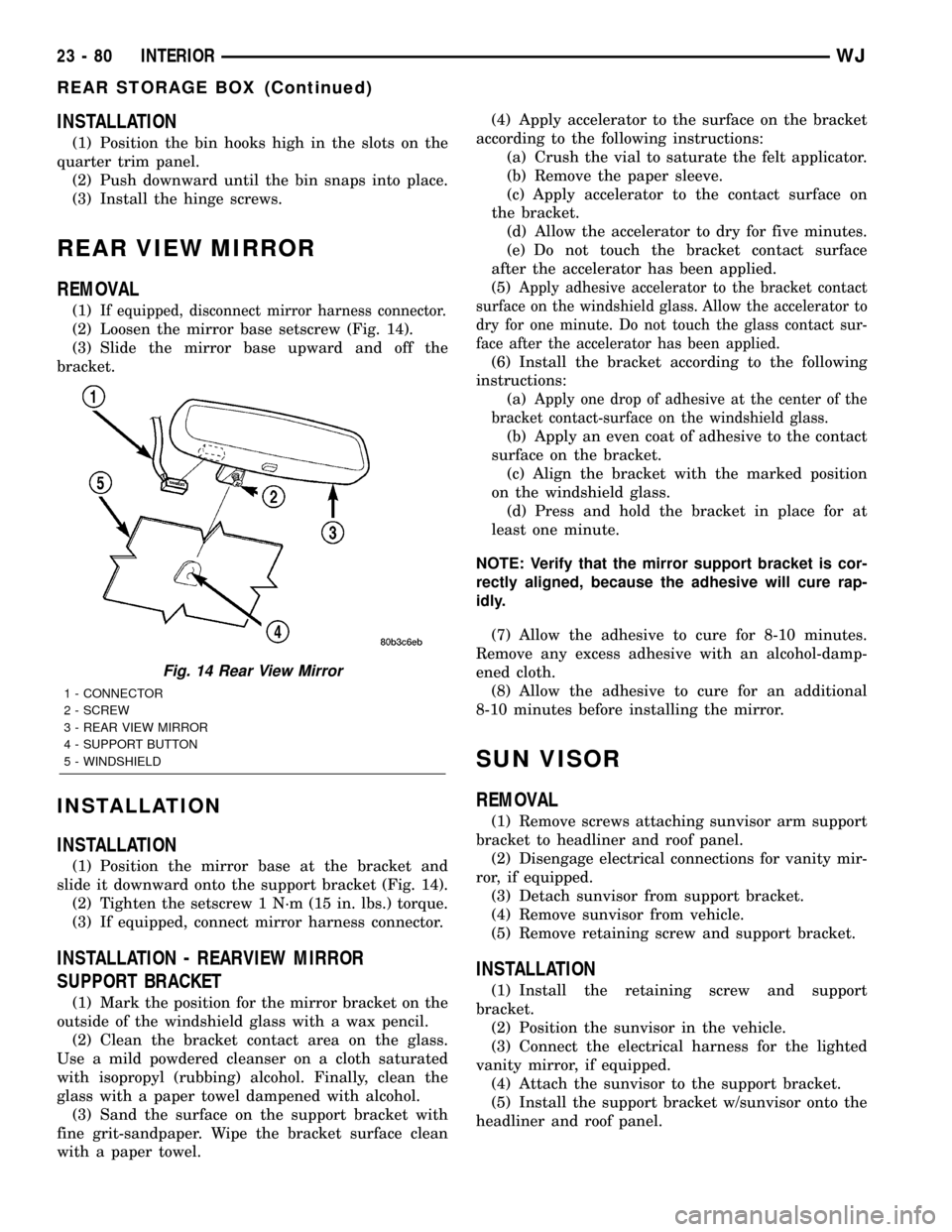
(2) Loosen the mirror base setscrew (Fig. 14).
(3) Slide the mirror base upward and off the
bracket.
INSTALLATION
INSTALLATION
(1) Position the mirror base at the bracket and
slide it downward onto the support bracket (Fig. 14).
(2) Tighten the setscrew 1 N´m (15 in. lbs.) torque.
(3) If equipped, connect mirror harness connector.
INSTALLATION - REARVIEW MIRROR
SUPPORT BRACKET
(1) Mark the position for the mirror bracket on the
outside of the windshield glass with a wax pencil.
(2) Clean the bracket contact area on the glass.
Use a mild powdered cleanser on a cloth saturated
with isopropyl (rubbing) alcohol. Finally, clean the
glass with a paper towel dampened with alcohol.
(3) Sand the surface on the support bracket with
fine grit-sandpaper. Wipe the bracket surface clean
with a paper towel.(4) Apply accelerator to the surface on the bracket
according to the following instructions:
(a) Crush the vial to saturate the felt applicator.
(b) Remove the paper sleeve.
(c) Apply accelerator to the contact surface on
the bracket.
(d) Allow the accelerator to dry for five minutes.
(e) Do not touch the bracket contact surface
after the accelerator has been applied.
(5)
Apply adhesive accelerator to the bracket contact
surface on the windshield glass. Allow the accelerator to
dry for one minute. Do not touch the glass contact sur-
face after the accelerator has been applied.
(6) Install the bracket according to the following
instructions:
(a)
Apply one drop of adhesive at the center of the
bracket contact-surface on the windshield glass.
(b) Apply an even coat of adhesive to the contact
surface on the bracket.
(c) Align the bracket with the marked position
on the windshield glass.
(d) Press and hold the bracket in place for at
least one minute.
NOTE: Verify that the mirror support bracket is cor-
rectly aligned, because the adhesive will cure rap-
idly.
(7) Allow the adhesive to cure for 8-10 minutes.
Remove any excess adhesive with an alcohol-damp-
ened cloth.
(8) Allow the adhesive to cure for an additional
8-10 minutes before installing the mirror.
SUN VISOR
REMOVAL
(1) Remove screws attaching sunvisor arm support
bracket to headliner and roof panel.
(2) Disengage electrical connections for vanity mir-
ror, if equipped.
(3) Detach sunvisor from support bracket.
(4) Remove sunvisor from vehicle.
(5) Remove retaining screw and support bracket.
INSTALLATION
(1) Install the retaining screw and support
bracket.
(2) Position the sunvisor in the vehicle.
(3) Connect the electrical harness for the lighted
vanity mirror, if equipped.
(4) Attach the sunvisor to the support bracket.
(5) Install the support bracket w/sunvisor onto the
headliner and roof panel.
Fig. 14 Rear View Mirror
1 - CONNECTOR
2 - SCREW
3 - REAR VIEW MIRROR
4 - SUPPORT BUTTON
5 - WINDSHIELD
23 - 80 INTERIORWJ
REAR STORAGE BOX (Continued)
Page 1967 of 2199
(3) Apply fence primer around edge of fence. Allow
at least eighteen minutes drying time.
(4) Apply a 10 mm (0.4 in.) bead of urethane
around window vinyl border location.
(5)
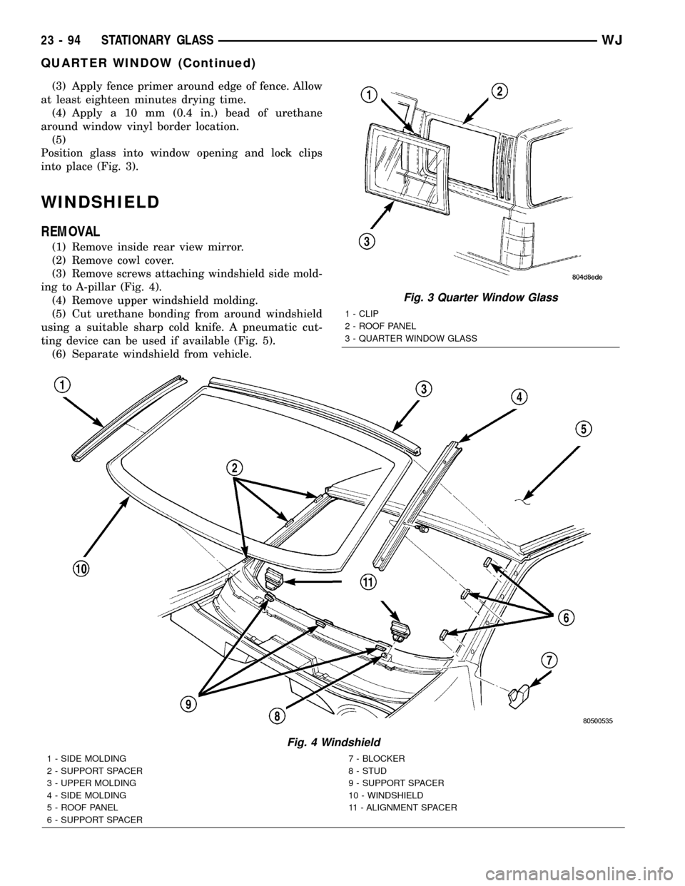
Position glass into window opening and lock clips
into place (Fig. 3).
WINDSHIELD
REMOVAL
(1) Remove inside rear view mirror.
(2) Remove cowl cover.
(3) Remove screws attaching windshield side mold-
ing to A-pillar (Fig. 4).
(4) Remove upper windshield molding.
(5) Cut urethane bonding from around windshield
using a suitable sharp cold knife. A pneumatic cut-
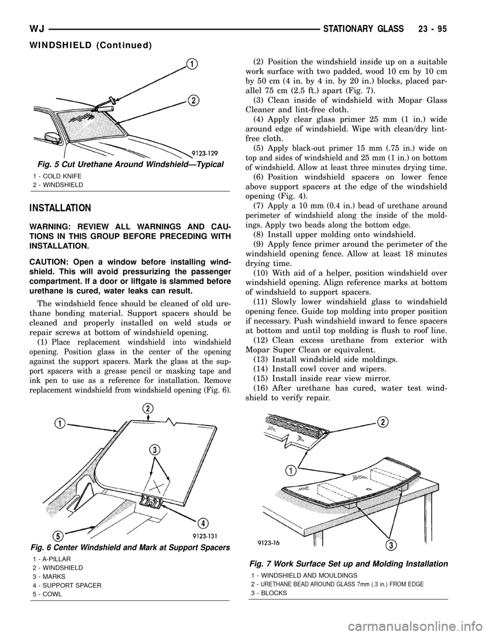
ting device can be used if available (Fig. 5).
(6) Separate windshield from vehicle.
Fig. 3 Quarter Window Glass
1 - CLIP
2 - ROOF PANEL
3 - QUARTER WINDOW GLASS
Fig. 4 Windshield
1 - SIDE MOLDING
2 - SUPPORT SPACER
3 - UPPER MOLDING
4 - SIDE MOLDING
5 - ROOF PANEL
6 - SUPPORT SPACER7 - BLOCKER
8 - STUD
9 - SUPPORT SPACER
10 - WINDSHIELD
11 - ALIGNMENT SPACER
23 - 94 STATIONARY GLASSWJ
QUARTER WINDOW (Continued)
Page 1968 of 2199
INSTALLATION
WARNING: REVIEW ALL WARNINGS AND CAU-
TIONS IN THIS GROUP BEFORE PRECEDING WITH
INSTALLATION.
CAUTION: Open a window before installing wind-
shield. This will avoid pressurizing the passenger
compartment. If a door or liftgate is slammed before
urethane is cured, water leaks can result.
The windshield fence should be cleaned of old ure-
thane bonding material. Support spacers should be
cleaned and properly installed on weld studs or
repair screws at bottom of windshield opening.
(1)
Place replacement windshield into windshield
opening. Position glass in the center of the opening
against the support spacers. Mark the glass at the sup-
port spacers with a grease pencil or masking tape and
ink pen to use as a reference for installation. Remove
replacement windshield from windshield opening (Fig. 6).
(2) Position the windshield inside up on a suitable
work surface with two padded, wood 10 cm by 10 cm
by 50 cm (4 in. by 4 in. by 20 in.) blocks, placed par-
allel 75 cm (2.5 ft.) apart (Fig. 7).
(3) Clean inside of windshield with Mopar Glass
Cleaner and lint-free cloth.
(4) Apply clear glass primer 25 mm (1 in.) wide
around edge of windshield. Wipe with clean/dry lint-
free cloth.
(5)
Apply black-out primer 15 mm (.75 in.) wide on
top and sides of windshield and 25 mm (1 in.) on bottom
of windshield. Allow at least three minutes drying time.
(6) Position windshield spacers on lower fence
above support spacers at the edge of the windshield
opening (Fig. 4).
(7)
Apply a 10 mm (0.4 in.) bead of urethane around
perimeter of windshield along the inside of the mold-
ings. Apply two beads along the bottom edge.
(8) Install upper molding onto windshield.
(9) Apply fence primer around the perimeter of the
windshield opening fence. Allow at least 18 minutes
drying time.
(10) With aid of a helper, position windshield over
windshield opening. Align reference marks at bottom
of windshield to support spacers.
(11) Slowly lower windshield glass to windshield
opening fence. Guide top molding into proper position
if necessary. Push windshield inward to fence spacers
at bottom and until top molding is flush to roof line.
(12) Clean excess urethane from exterior with
Mopar Super Clean or equivalent.
(13) Install windshield side moldings.
(14) Install cowl cover and wipers.
(15) Install inside rear view mirror.
(16) After urethane has cured, water test wind-
shield to verify repair.
Fig. 6 Center Windshield and Mark at Support Spacers
1 - A-PILLAR
2 - WINDSHIELD
3 - MARKS
4 - SUPPORT SPACER
5 - COWLFig. 7 Work Surface Set up and Molding Installation
1 - WINDSHIELD AND MOULDINGS
2-
URETHANE BEAD AROUND GLASS 7mm (.3 in.) FROM EDGE
3 - BLOCKS
Fig. 5 Cut Urethane Around WindshieldÐTypical
1 - COLD KNIFE
2 - WINDSHIELD
WJSTATIONARY GLASS 23 - 95
WINDSHIELD (Continued)