2003 JEEP GRAND CHEROKEE spec
[x] Cancel search: specPage 2010 of 2199
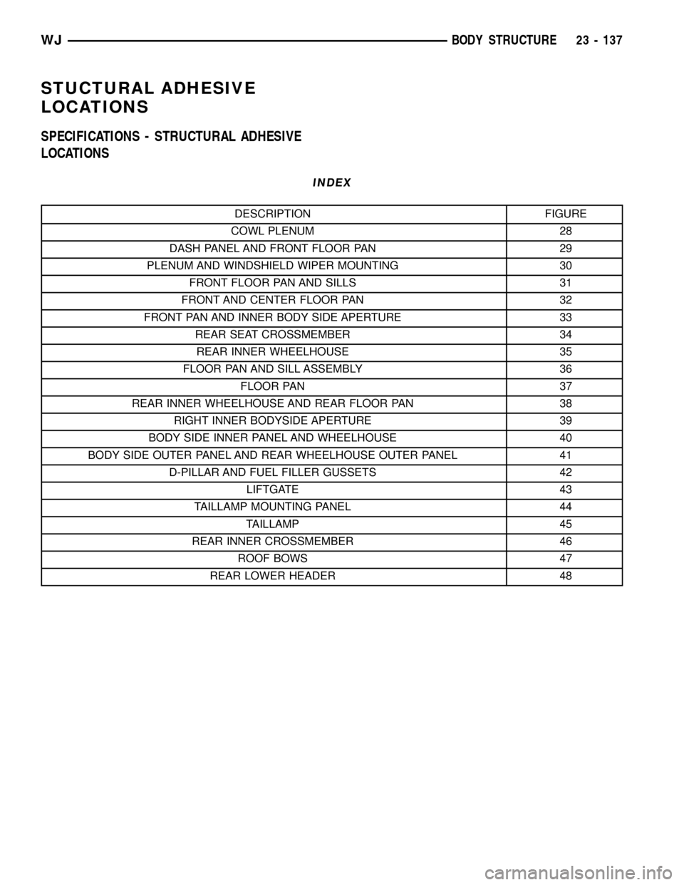
STUCTURAL ADHESIVE
LOCATIONS
SPECIFICATIONS - STRUCTURAL ADHESIVE
LOCATIONS
INDEX
DESCRIPTION FIGURE
COWL PLENUM 28
DASH PANEL AND FRONT FLOOR PAN 29
PLENUM AND WINDSHIELD WIPER MOUNTING 30
FRONT FLOOR PAN AND SILLS 31
FRONT AND CENTER FLOOR PAN 32
FRONT PAN AND INNER BODY SIDE APERTURE 33
REAR SEAT CROSSMEMBER 34
REAR INNER WHEELHOUSE 35
FLOOR PAN AND SILL ASSEMBLY 36
FLOOR PAN 37
REAR INNER WHEELHOUSE AND REAR FLOOR PAN 38
RIGHT INNER BODYSIDE APERTURE 39
BODY SIDE INNER PANEL AND WHEELHOUSE 40
BODY SIDE OUTER PANEL AND REAR WHEELHOUSE OUTER PANEL 41
D-PILLAR AND FUEL FILLER GUSSETS 42
LIFTGATE 43
TAILLAMP MOUNTING PANEL 44
TAILLAMP 45
REAR INNER CROSSMEMBER 46
ROOF BOWS 47
REAR LOWER HEADER 48
WJBODY STRUCTURE 23 - 137
Page 2026 of 2199
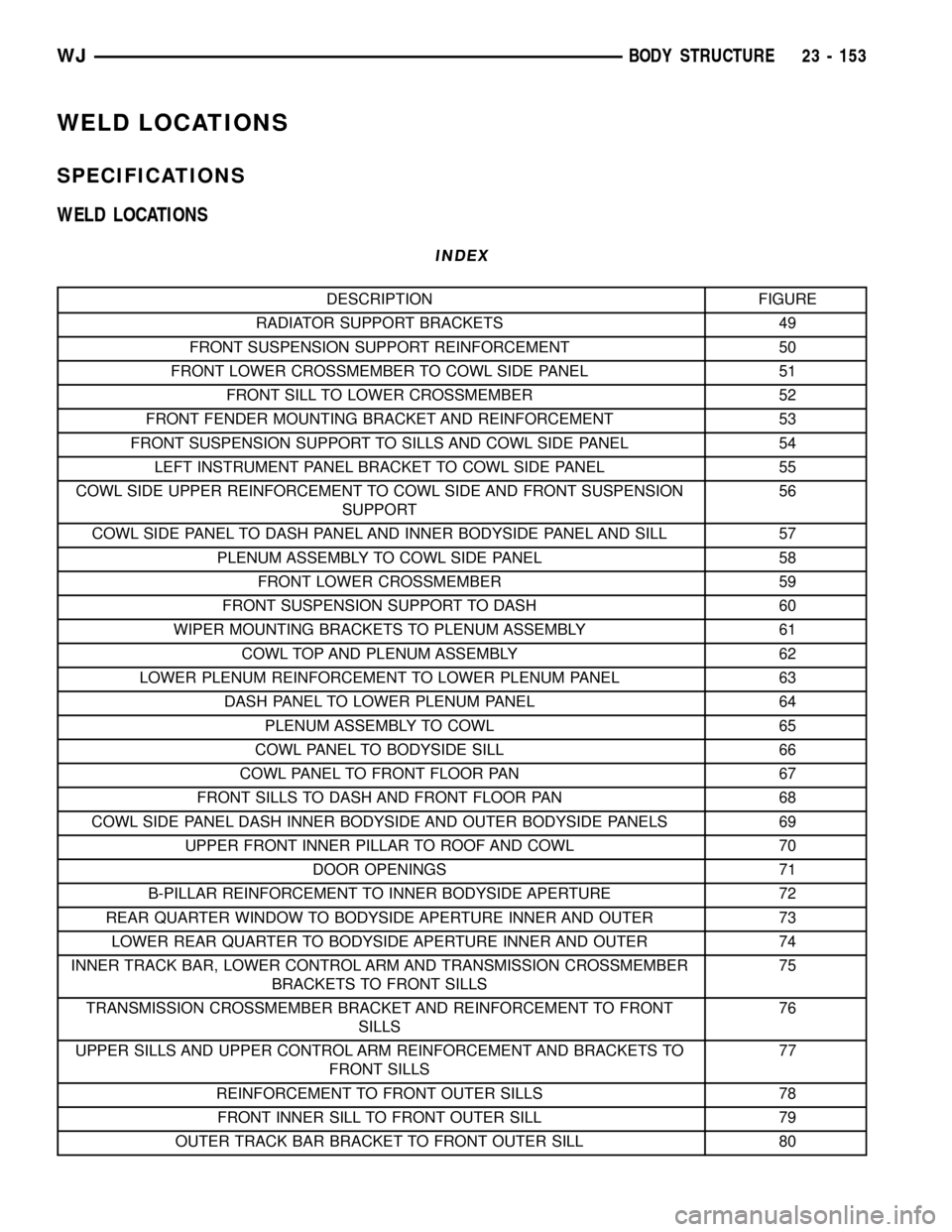
WELD LOCATIONS
SPECIFICATIONS
WELD LOCATIONS
INDEX
DESCRIPTION FIGURE
RADIATOR SUPPORT BRACKETS 49
FRONT SUSPENSION SUPPORT REINFORCEMENT 50
FRONT LOWER CROSSMEMBER TO COWL SIDE PANEL 51
FRONT SILL TO LOWER CROSSMEMBER 52
FRONT FENDER MOUNTING BRACKET AND REINFORCEMENT 53
FRONT SUSPENSION SUPPORT TO SILLS AND COWL SIDE PANEL 54
LEFT INSTRUMENT PANEL BRACKET TO COWL SIDE PANEL 55
COWL SIDE UPPER REINFORCEMENT TO COWL SIDE AND FRONT SUSPENSION
SUPPORT56
COWL SIDE PANEL TO DASH PANEL AND INNER BODYSIDE PANEL AND SILL 57
PLENUM ASSEMBLY TO COWL SIDE PANEL 58
FRONT LOWER CROSSMEMBER 59
FRONT SUSPENSION SUPPORT TO DASH 60
WIPER MOUNTING BRACKETS TO PLENUM ASSEMBLY 61
COWL TOP AND PLENUM ASSEMBLY 62
LOWER PLENUM REINFORCEMENT TO LOWER PLENUM PANEL 63
DASH PANEL TO LOWER PLENUM PANEL 64
PLENUM ASSEMBLY TO COWL 65
COWL PANEL TO BODYSIDE SILL 66
COWL PANEL TO FRONT FLOOR PAN 67
FRONT SILLS TO DASH AND FRONT FLOOR PAN 68
COWL SIDE PANEL DASH INNER BODYSIDE AND OUTER BODYSIDE PANELS 69
UPPER FRONT INNER PILLAR TO ROOF AND COWL 70
DOOR OPENINGS 71
B-PILLAR REINFORCEMENT TO INNER BODYSIDE APERTURE 72
REAR QUARTER WINDOW TO BODYSIDE APERTURE INNER AND OUTER 73
LOWER REAR QUARTER TO BODYSIDE APERTURE INNER AND OUTER 74
INNER TRACK BAR, LOWER CONTROL ARM AND TRANSMISSION CROSSMEMBER
BRACKETS TO FRONT SILLS75
TRANSMISSION CROSSMEMBER BRACKET AND REINFORCEMENT TO FRONT
SILLS76
UPPER SILLS AND UPPER CONTROL ARM REINFORCEMENT AND BRACKETS TO
FRONT SILLS77
REINFORCEMENT TO FRONT OUTER SILLS 78
FRONT INNER SILL TO FRONT OUTER SILL 79
OUTER TRACK BAR BRACKET TO FRONT OUTER SILL 80
WJBODY STRUCTURE 23 - 153
Page 2078 of 2199

HEATING & AIR CONDITIONING
TABLE OF CONTENTS
page page
HEATING & AIR CONDITIONING
DESCRIPTION
DESCRIPTION - COOLING SYSTEM
REQUIREMENTS.......................1
DESCRIPTION - HEATER AND AIR
CONDITIONER........................1
DESCRIPTION - REFRIGERANT SYSTEM
SERVICE PORT........................1
OPERATION
OPERATION - HEATER AND AIR
CONDITIONER........................2
OPERATION - REFRIGERANT SYSTEM
SERVICE PORT........................2DIAGNOSIS AND TESTING
DIAGNOSIS AND TESTING - A/C
PERFORMANCE.......................2
DIAGNOSIS AND TESTING - HEATER
PERFORMANCE.......................6
STANDARD PROCEDURE - DIODE
REPLACEMENT.......................6
SPECIFICATIONS
A/C APPLICATION TABLE................7
TORQUE SPECIFICATIONS..............8
CONTROLS.............................9
DISTRIBUTION..........................36
PLUMBING.............................51
HEATING & AIR
CONDITIONING
DESCRIPTION
DESCRIPTION - COOLING SYSTEM
REQUIREMENTS
To maintain the performance level of the heating-
air conditioning system, the engine cooling system
must be properly maintained. The use of a bug
screen is not recommended. Any obstructions in front
of the radiator or condenser will reduce the perfor-
mance of the air conditioning and engine cooling sys-
tems.
The engine cooling system includes the heater core
and the heater hoses. Refer to Cooling for more infor-
mation before opening, or attempting any service to
the engine cooling system.
DESCRIPTION - HEATER AND AIR
CONDITIONER
A manual temperature control type heating-air
conditioning system is standard factory-installed
equipment on this model. An electronically controlled
Automatic Zone Control (AZC) type heating-air con-
ditioning system is an available factory-installed
option.
All vehicles are equipped with a common HVAC
housing assembly (Fig. 1). The system combines air
conditioning, heating, and ventilating capabilities in
a single unit housing mounted under the instrument
panel.DESCRIPTION - REFRIGERANT SYSTEM
SERVICE PORT
The two refrigerant system service ports are used
to charge, recover/recycle, evacuate, and test the air
conditioning refrigerant system. Unique service port
coupler sizes are used on the R-134a system to
ensure that the refrigerant system is not accidentally
contaminated by the use of the wrong refrigerant
(R-12), or refrigerant system service equipment.
Fig. 1 Blend-Air HVAC System - (typical)
1 - Blend Door
2 - Expansion Valve
3 - Evaporator Core
4 - Blower Assembly
5 - Recirculation Door
6 - Evaporator Probe
7 - Heater Core
8 - Heat/Defrost Door
9 - Panel/Defrost Door
WJHEATING & AIR CONDITIONING 24 - 1
Page 2079 of 2199

OPERATION
OPERATION - HEATER AND AIR CONDITIONER
Outside fresh air enters the vehicle through the
cowl top opening at the base of the windshield, and
passes through a plenum chamber to the HVAC sys-
tem blower housing. Air flow velocity can then be
adjusted with the blower motor speed selector switch
on the a/c heater control panel. The air intake open-
ings must be kept free of snow, ice, leaves, and other
obstructions for the HVAC system to receive a suffi-
cient volume of outside air.
It is also important to keep the air intake openings
clear of debris because leaf particles and other debris
that is small enough to pass through the cowl ple-
num screen can accumulate within the HVAC hous-
ing. The closed, warm, damp and dark environment
created within the HVAC housing is ideal for the
growth of certain molds, mildews and other fungi.
Any accumulation of decaying plant matter provides
an additional food source for fungal spores, which
enter the housing with the fresh air. Excess debris,
as well as objectionable odors created by decaying
plant matter and growing fungi can be discharged
into the passenger compartment during HVAC sys-
tem operation.
Both the manual and AZC heater and air condi-
tioner are blend-air type systems. In a blend-air sys-
tem, a blend door controls the amount of
unconditioned air (or cooled air from the evaporator)
that is allowed to flow through, or around, the heater
core. A temperature control knob on the a/c heater
control panel determines the discharge air tempera-
ture by energizing the blend door actuator, which
operates the blend door. This allows an almost imme-
diate control of the output air temperature of the sys-
tem. The AZC system will have separate blend doors
and temperature controls for each front seat occu-
pant.
The mode control knob on the a/c heater control
panel is used to direct the conditioned air to the
selected system outlets. On manual temperature con-
trol systems, the mode control knob switches engine
vacuum to control the mode doors, which are oper-
ated by vacuum actuators. On AZC systems, the
mode control knob switches electrical current to con-
trol the mode doors, which are operated by electronic
actuators.
The outside air intake can be shut off on manual
temperature control systems by selecting the Recircu-
lation Mode with the mode control knob. The outside
air intake can be shut off on Automatic Zone Control
(AZC) type system by pushing the Recirculation
Mode button. This will operate the recirculation door
that closes off the outside fresh air intake and recir-
culates the air that is already inside the vehicle.The air conditioner for all models is designed for
the use of non-CFC, R-134a refrigerant. The air con-
ditioning system has an evaporator to cool and dehu-
midify the incoming air prior to blending it with the
heated air. This air conditioning system uses a ther-
mal expansion valve to meter refrigerant flow to the
evaporator coil. To maintain minimum evaporator
temperature and prevent evaporator freezing, the
system utilizes an evaporator thermister probe with
the appropriate operating logic located in the body
control module (BCM).
OPERATION - REFRIGERANT SYSTEM SERVICE
PORT
The high pressure service port is located on the liq-
uid line near the receiver/drier. The low pressure ser-
vice port is located on the suction line near the
evaporator at the rear of the engine compartment.
Each of the service ports has a threaded plastic
protective cap installed over it from the factory. After
servicing the refrigerant system, always reinstall
both of the service port caps.
DIAGNOSIS AND TESTING
DIAGNOSIS AND TESTING - A/C
PERFORMANCE
The air conditioning system is designed to provide
the passenger compartment with low temperature
and low specific humidity air. The evaporator, located
in the HVAC housing on the dash panel below the
instrument panel, is cooled to temperatures near the
freezing point. As warm damp air passes through the
cooled evaporator, the air transfers its heat to the
refrigerant in the evaporator and the moisture in the
air condenses on the evaporator fins. During periods
of high heat and humidity, an air conditioning sys-
tem will be more effective in the Recirculation Mode.
With the system in the Recirculation Mode, only air
from the passenger compartment passes through the
evaporator. As the passenger compartment air dehu-
midifies, the air conditioning system performance
levels improve.
Humidity has an important bearing on the tempera-
ture of the air delivered to the interior of the vehicle. It
is important to understand the effect that humidity has
on the performance of the air conditioning system.
When humidity is high, the evaporator has to perform a
double duty. It must lower the air temperature, and it
must lower the temperature of the moisture in the air
that condenses on the evaporator fins. Condensing the
moisture in the air transfers heat energy into the evap-
orator fins and tubing. This reduces the amount of heat
the evaporator can absorb from the air. High humidity
greatly reduces the ability of the evaporator to lower
the temperature of the air.
24 - 2 HEATING & AIR CONDITIONINGWJ
HEATING & AIR CONDITIONING (Continued)
Page 2081 of 2199
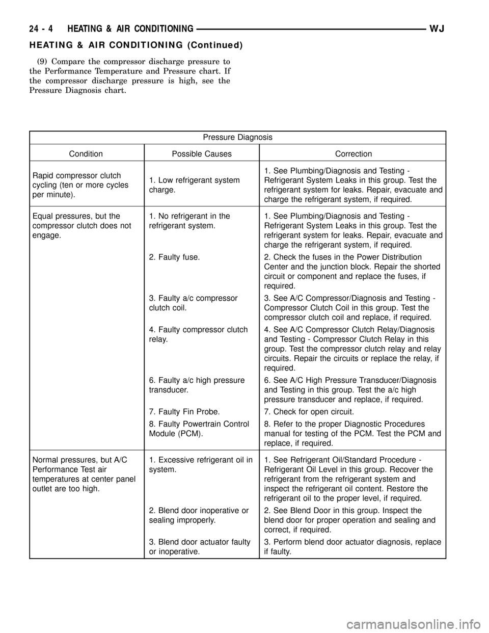
(9) Compare the compressor discharge pressure to
the Performance Temperature and Pressure chart. If
the compressor discharge pressure is high, see the
Pressure Diagnosis chart.
Pressure Diagnosis
Condition Possible Causes Correction
Rapid compressor clutch
cycling (ten or more cycles
per minute).1. Low refrigerant system
charge.1. See Plumbing/Diagnosis and Testing -
Refrigerant System Leaks in this group. Test the
refrigerant system for leaks. Repair, evacuate and
charge the refrigerant system, if required.
Equal pressures, but the
compressor clutch does not
engage.1. No refrigerant in the
refrigerant system.1. See Plumbing/Diagnosis and Testing -
Refrigerant System Leaks in this group. Test the
refrigerant system for leaks. Repair, evacuate and
charge the refrigerant system, if required.
2. Faulty fuse. 2. Check the fuses in the Power Distribution
Center and the junction block. Repair the shorted
circuit or component and replace the fuses, if
required.
3. Faulty a/c compressor
clutch coil.3. See A/C Compressor/Diagnosis and Testing -
Compressor Clutch Coil in this group. Test the
compressor clutch coil and replace, if required.
4. Faulty compressor clutch
relay.4. See A/C Compressor Clutch Relay/Diagnosis
and Testing - Compressor Clutch Relay in this
group. Test the compressor clutch relay and relay
circuits. Repair the circuits or replace the relay, if
required.
6. Faulty a/c high pressure
transducer.6. See A/C High Pressure Transducer/Diagnosis
and Testing in this group. Test the a/c high
pressure transducer and replace, if required.
7. Faulty Fin Probe. 7. Check for open circuit.
8. Faulty Powertrain Control
Module (PCM).8. Refer to the proper Diagnostic Procedures
manual for testing of the PCM. Test the PCM and
replace, if required.
Normal pressures, but A/C
Performance Test air
temperatures at center panel
outlet are too high.1. Excessive refrigerant oil in
system.1. See Refrigerant Oil/Standard Procedure -
Refrigerant Oil Level in this group. Recover the
refrigerant from the refrigerant system and
inspect the refrigerant oil content. Restore the
refrigerant oil to the proper level, if required.
2. Blend door inoperative or
sealing improperly.2. See Blend Door in this group. Inspect the
blend door for proper operation and sealing and
correct, if required.
3. Blend door actuator faulty
or inoperative.3. Perform blend door actuator diagnosis, replace
if faulty.
24 - 4 HEATING & AIR CONDITIONINGWJ
HEATING & AIR CONDITIONING (Continued)
Page 2082 of 2199
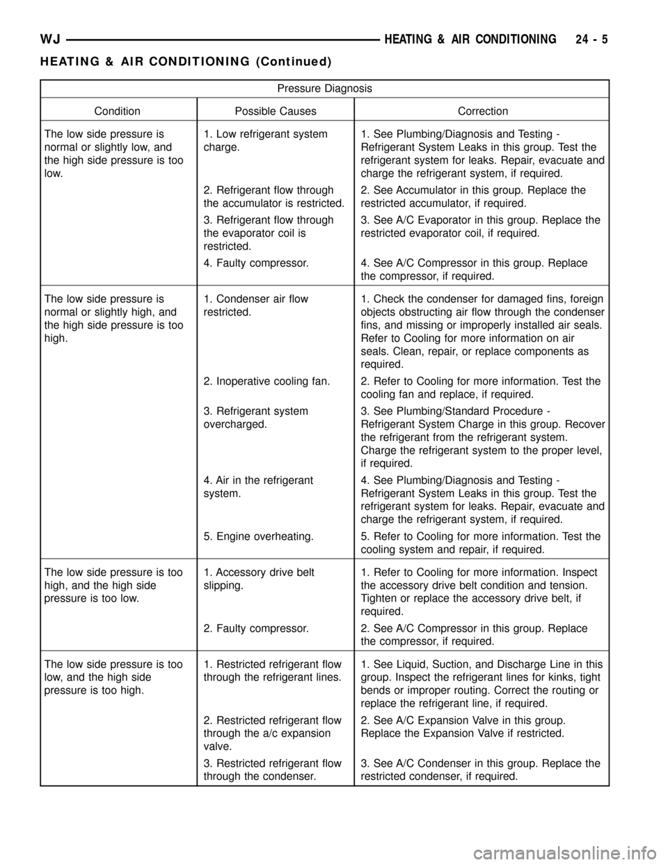
Pressure Diagnosis
Condition Possible Causes Correction
The low side pressure is
normal or slightly low, and
the high side pressure is too
low.1. Low refrigerant system
charge.1. See Plumbing/Diagnosis and Testing -
Refrigerant System Leaks in this group. Test the
refrigerant system for leaks. Repair, evacuate and
charge the refrigerant system, if required.
2. Refrigerant flow through
the accumulator is restricted.2. See Accumulator in this group. Replace the
restricted accumulator, if required.
3. Refrigerant flow through
the evaporator coil is
restricted.3. See A/C Evaporator in this group. Replace the
restricted evaporator coil, if required.
4. Faulty compressor. 4. See A/C Compressor in this group. Replace
the compressor, if required.
The low side pressure is
normal or slightly high, and
the high side pressure is too
high.1. Condenser air flow
restricted.1. Check the condenser for damaged fins, foreign
objects obstructing air flow through the condenser
fins, and missing or improperly installed air seals.
Refer to Cooling for more information on air
seals. Clean, repair, or replace components as
required.
2. Inoperative cooling fan. 2. Refer to Cooling for more information. Test the
cooling fan and replace, if required.
3. Refrigerant system
overcharged.3. See Plumbing/Standard Procedure -
Refrigerant System Charge in this group. Recover
the refrigerant from the refrigerant system.
Charge the refrigerant system to the proper level,
if required.
4. Air in the refrigerant
system.4. See Plumbing/Diagnosis and Testing -
Refrigerant System Leaks in this group. Test the
refrigerant system for leaks. Repair, evacuate and
charge the refrigerant system, if required.
5. Engine overheating. 5. Refer to Cooling for more information. Test the
cooling system and repair, if required.
The low side pressure is too
high, and the high side
pressure is too low.1. Accessory drive belt
slipping.1. Refer to Cooling for more information. Inspect
the accessory drive belt condition and tension.
Tighten or replace the accessory drive belt, if
required.
2. Faulty compressor. 2. See A/C Compressor in this group. Replace
the compressor, if required.
The low side pressure is too
low, and the high side
pressure is too high.1. Restricted refrigerant flow
through the refrigerant lines.1. See Liquid, Suction, and Discharge Line in this
group. Inspect the refrigerant lines for kinks, tight
bends or improper routing. Correct the routing or
replace the refrigerant line, if required.
2. Restricted refrigerant flow
through the a/c expansion
valve.2. See A/C Expansion Valve in this group.
Replace the Expansion Valve if restricted.
3. Restricted refrigerant flow
through the condenser.3. See A/C Condenser in this group. Replace the
restricted condenser, if required.
WJHEATING & AIR CONDITIONING 24 - 5
HEATING & AIR CONDITIONING (Continued)
Page 2083 of 2199
DIAGNOSIS AND TESTING - HEATER
PERFORMANCE
Before performing the following tests, refer to Cool-
ing for the procedures to check the radiator coolant
level, serpentine drive belt tension, radiator air flow
and the radiator fan operation. Also be certain that
the accessory vacuum supply line is connected at the
engine intake manifold for the manual temperature
control system.
MAXIMUM HEATER OUTPUT
Engine coolant is delivered to the heater core
through two heater hoses. With the engine idling at
normal operating temperature, set the temperature
control knob in the full hot position, the mode control
switch knob in the floor heat position, and the blower
motor switch knob in the highest speed position.
Using a test thermometer, check the temperature of
the air being discharged at the HVAC housing floor
outlets. Compare the test thermometer reading to the
Temperature Reference chart.
Temperature Reference
Ambient Air Temperature15.5É C
(60É F)21.1É C
(70É F)26.6É C
(80É F)32.2É C
(90É F)
Minimum Air Temperature at
Floor Outlet62.2É C
(144É F)63.8É C
(147É F)65.5É C
(150É F)67.2É C
(153É F)
If the floor outlet air temperature is too low, refer
to Cooling to check the engine coolant temperature
specifications. Both of the heater hoses should be hot
to the touch. The coolant return heater hose should
be slightly cooler than the coolant supply heater
hose. If the return hose is much cooler than the sup-
ply hose, locate and repair the engine coolant flow
obstruction in the cooling system. Refer to Cooling
for the procedures.
OBSTRUCTED COOLANT FLOW
Possible locations or causes of obstructed coolant
flow:
²Pinched or kinked heater hoses.
²Improper heater hose routing.
²Plugged heater hoses or supply and return ports
at the cooling system connections.
²A plugged heater core.
If proper coolant flow through the cooling system is
verified, and heater outlet air temperature is still
low, a mechanical problem may exist.
MECHANICAL PROBLEMS
Possible locations or causes of insufficient heat:
²An obstructed cowl air intake.
²Obstructed heater system outlets.
²A blend door not functioning properly.
TEMPERATURE CONTROL
If the heater outlet air temperature cannot be
adjusted with the temperature control knob(s) on the
A/C Heater control panel, the following could require
service:
²The A/C heater control.
²The blend door actuator(s).
²The wire harness circuits for the A/C heater con-
trol or the blend door actuator(s).²The blend door(s).
²Improper engine coolant temperature.
STANDARD PROCEDURE - DIODE
REPLACEMENT
(1) Disconnect and isolate the negative battery
cable.
(2) Locate the diode in the harness, and remove
the protective covering.
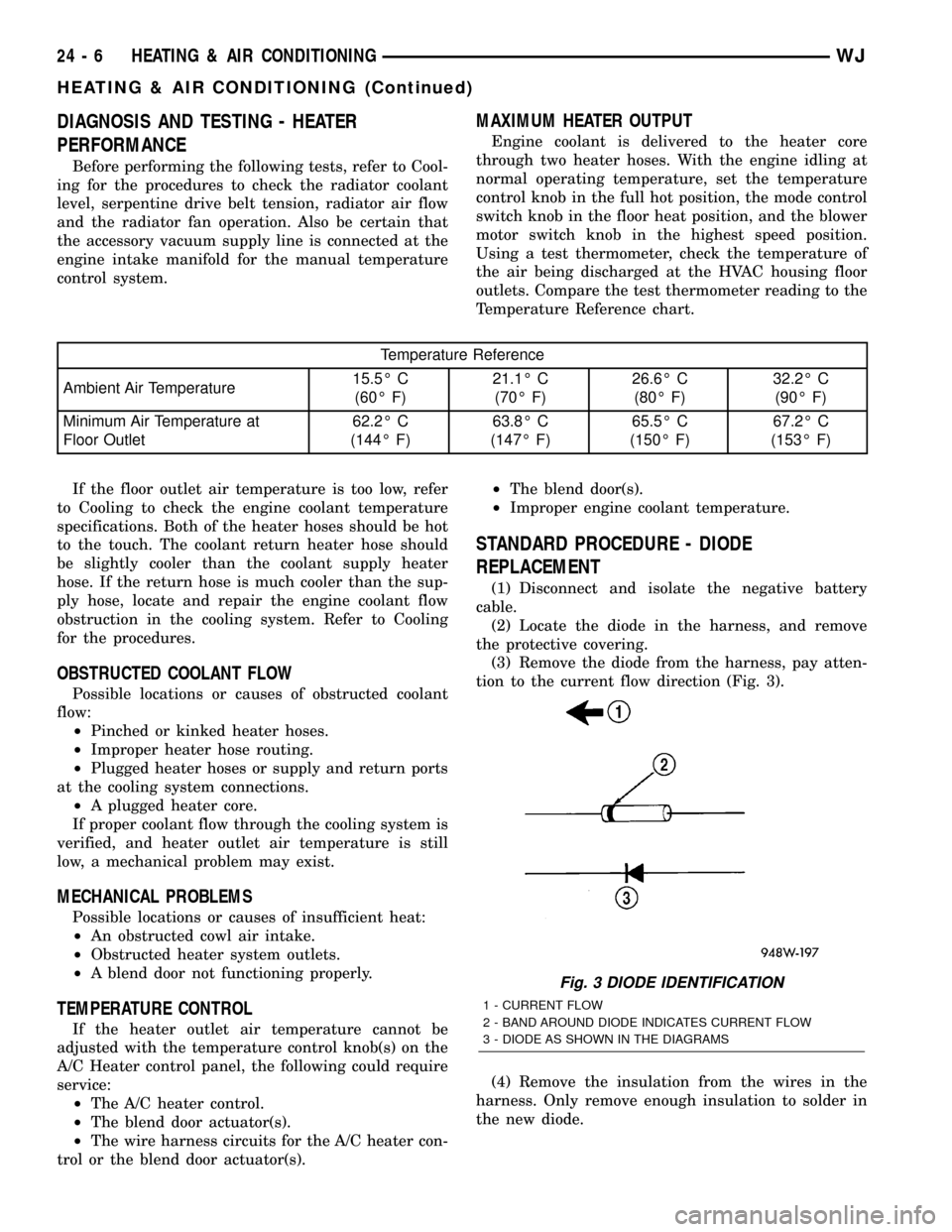
(3) Remove the diode from the harness, pay atten-
tion to the current flow direction (Fig. 3).
(4) Remove the insulation from the wires in the
harness. Only remove enough insulation to solder in
the new diode.
Fig. 3 DIODE IDENTIFICATION
1 - CURRENT FLOW
2 - BAND AROUND DIODE INDICATES CURRENT FLOW
3 - DIODE AS SHOWN IN THE DIAGRAMS
24 - 6 HEATING & AIR CONDITIONINGWJ
HEATING & AIR CONDITIONING (Continued)
Page 2084 of 2199
(5) Install the new diode in the harness, making
sure current flow is correct. If necessary refer to the
appropriate wiring diagram for current flow.
(6) Solder the connection together using rosin core
type solder only.Do not use acid core solder.
(7) Tape the diode to the harness using electrical
tape making, sure the diode is completely sealed
from the elements.
(8) Re-connect the battery, and test affected sys-
tems.SPECIFICATIONS
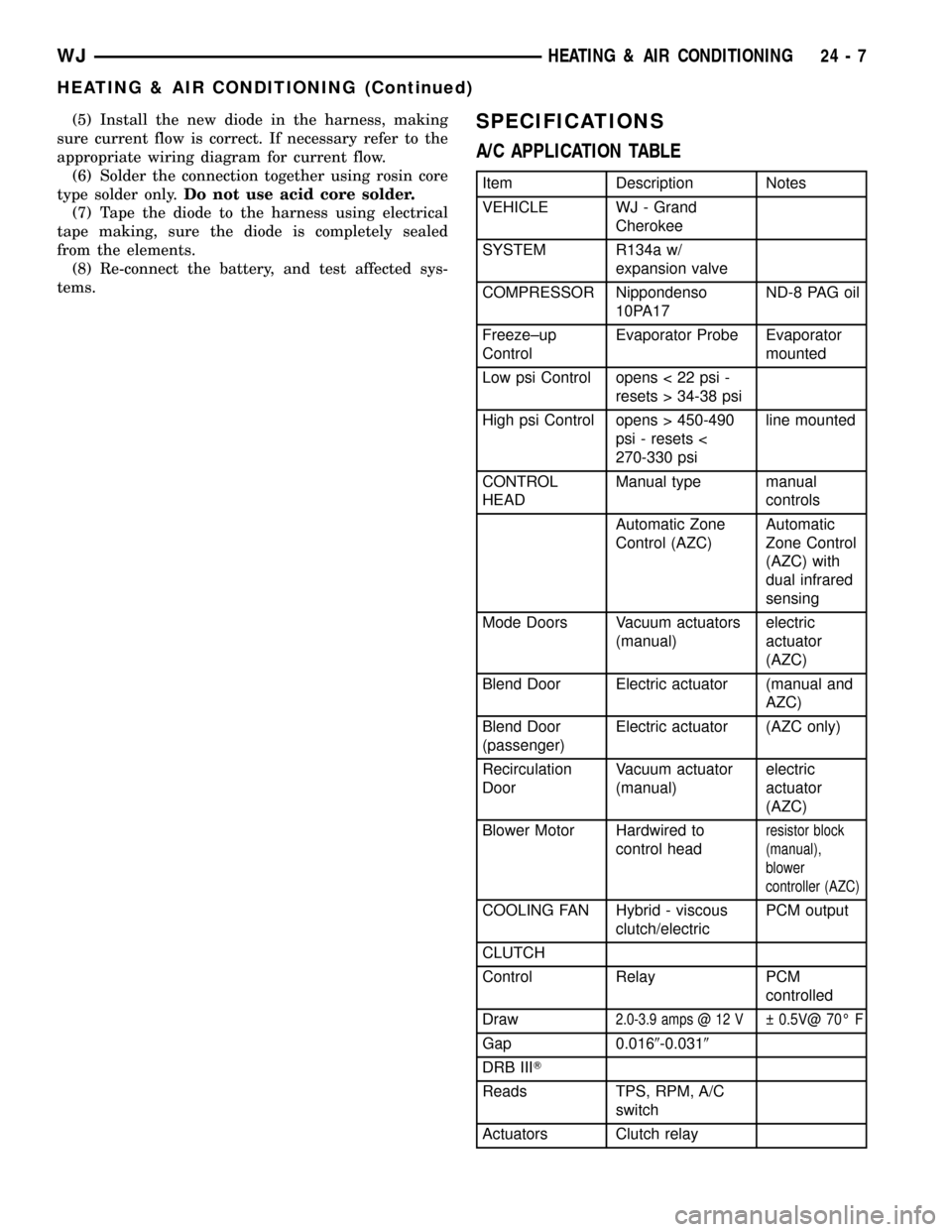
A/C APPLICATION TABLE
Item Description Notes
VEHICLE WJ - Grand
Cherokee
SYSTEM R134a w/
expansion valve
COMPRESSOR Nippondenso
10PA17ND-8 PAG oil
Freeze±up
ControlEvaporator Probe Evaporator
mounted
Low psi Control opens < 22 psi -
resets > 34-38 psi
High psi Control opens > 450-490
psi - resets <
270-330 psiline mounted
CONTROL
HEADManual type manual
controls
Automatic Zone
Control (AZC)Automatic
Zone Control
(AZC) with
dual infrared
sensing
Mode Doors Vacuum actuators
(manual)electric
actuator
(AZC)
Blend Door Electric actuator (manual and
AZC)
Blend Door
(passenger)Electric actuator (AZC only)
Recirculation
DoorVacuum actuator
(manual)electric
actuator
(AZC)
Blower Motor Hardwired to
control head
resistor block
(manual),
blower
controller (AZC)
COOLING FAN Hybrid - viscous
clutch/electricPCM output
CLUTCH
Control Relay PCM
controlled
Draw
2.0-3.9 amps @ 12 V 0.5V@ 70É F
Gap 0.0169-0.0319
DRB IIIT
Reads TPS, RPM, A/C
switch
Actuators Clutch relay
WJHEATING & AIR CONDITIONING 24 - 7
HEATING & AIR CONDITIONING (Continued)