Page 1846 of 2199
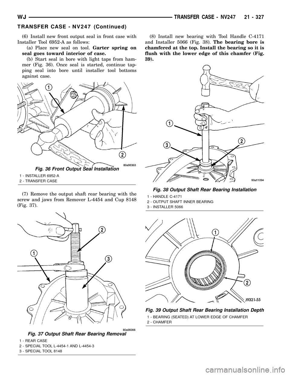
(6) Install new front output seal in front case with
Installer Tool 6952-A as follows:
(a) Place new seal on tool.Garter spring on
seal goes toward interior of case.
(b) Start seal in bore with light taps from ham-
mer (Fig. 36). Once seal is started, continue tap-
ping seal into bore until installer tool bottoms
against case.
(7) Remove the output shaft rear bearing with the
screw and jaws from Remover L-4454 and Cup 8148
(Fig. 37).(8) Install new bearing with Tool Handle C-4171
and Installer 5066 (Fig. 38).The bearing bore is
chamfered at the top. Install the bearing so it is
flush with the lower edge of this chamfer (Fig.
39).
Fig. 37 Output Shaft Rear Bearing Removal
1 - REAR CASE
2 - SPECIAL TOOL L-4454-1 AND L-4454-3
3 - SPECIAL TOOL 8148
Fig. 36 Front Output Seal Installation
1 - INSTALLER 6952-A
2 - TRANSFER CASE
Fig. 38 Output Shaft Rear Bearing Installation
1 - HANDLE C-4171
2 - OUTPUT SHAFT INNER BEARING
3 - INSTALLER 5066
Fig. 39 Output Shaft Rear Bearing Installation Depth
1 - BEARING (SEATED) AT LOWER EDGE OF CHAMFER
2 - CHAMFER
WJTRANSFER CASE - NV247 21 - 327
TRANSFER CASE - NV247 (Continued)
Page 1847 of 2199
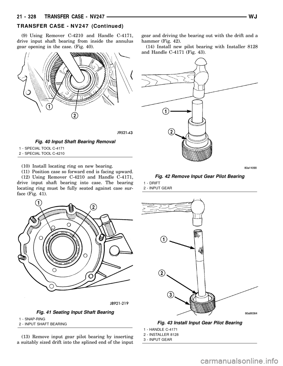
(9) Using Remover C-4210 and Handle C-4171,
drive input shaft bearing from inside the annulus
gear opening in the case. (Fig. 40).
(10) Install locating ring on new bearing.
(11) Position case so forward end is facing upward.
(12) Using Remover C-4210 and Handle C-4171,
drive input shaft bearing into case. The bearing
locating ring must be fully seated against case sur-
face (Fig. 41).
(13) Remove input gear pilot bearing by inserting
a suitably sized drift into the splined end of the inputgear and driving the bearing out with the drift and a
hammer (Fig. 42).
(14) Install new pilot bearing with Installer 8128
and Handle C-4171 (Fig. 43).
Fig. 40 Input Shaft Bearing Removal
1 - SPECIAL TOOL C-4171
2 - SPECIAL TOOL C-4210
Fig. 41 Seating Input Shaft Bearing
1 - SNAP-RING
2 - INPUT SHAFT BEARING
Fig. 42 Remove Input Gear Pilot Bearing
1 - DRIFT
2 - INPUT GEAR
Fig. 43 Install Input Gear Pilot Bearing
1 - HANDLE C-4171
2 - INSTALLER 8128
3 - INPUT GEAR
21 - 328 TRANSFER CASE - NV247WJ
TRANSFER CASE - NV247 (Continued)
Page 1848 of 2199
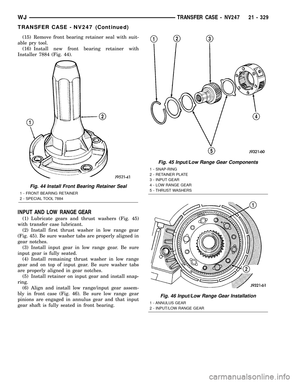
(15) Remove front bearing retainer seal with suit-
able pry tool.
(16) Install new front bearing retainer with
Installer 7884 (Fig. 44).
INPUT AND LOW RANGE GEAR
(1) Lubricate gears and thrust washers (Fig. 45)
with transfer case lubricant.
(2) Install first thrust washer in low range gear
(Fig. 45). Be sure washer tabs are properly aligned in
gear notches.
(3) Install input gear in low range gear. Be sure
input gear is fully seated.
(4) Install remaining thrust washer in low range
gear and on top of input gear. Be sure washer tabs
are properly aligned in gear notches.
(5) Install retainer on input gear and install snap-
ring.
(6) Align and install low range/input gear assem-
bly in front case (Fig. 46). Be sure low range gear
pinions are engaged in annulus gear and that input
gear shaft is fully seated in front bearing.
Fig. 44 Install Front Bearing Retainer Seal
1 - FRONT BEARING RETAINER
2 - SPECIAL TOOL 7884
Fig. 45 Input/Low Range Gear Components
1 - SNAP-RING
2 - RETAINER PLATE
3 - INPUT GEAR
4 - LOW RANGE GEAR
5 - THRUST WASHERS
Fig. 46 Input/Low Range Gear Installation
1 - ANNULUS GEAR
2 - INPUT/LOW RANGE GEAR
WJTRANSFER CASE - NV247 21 - 329
TRANSFER CASE - NV247 (Continued)
Page 1849 of 2199
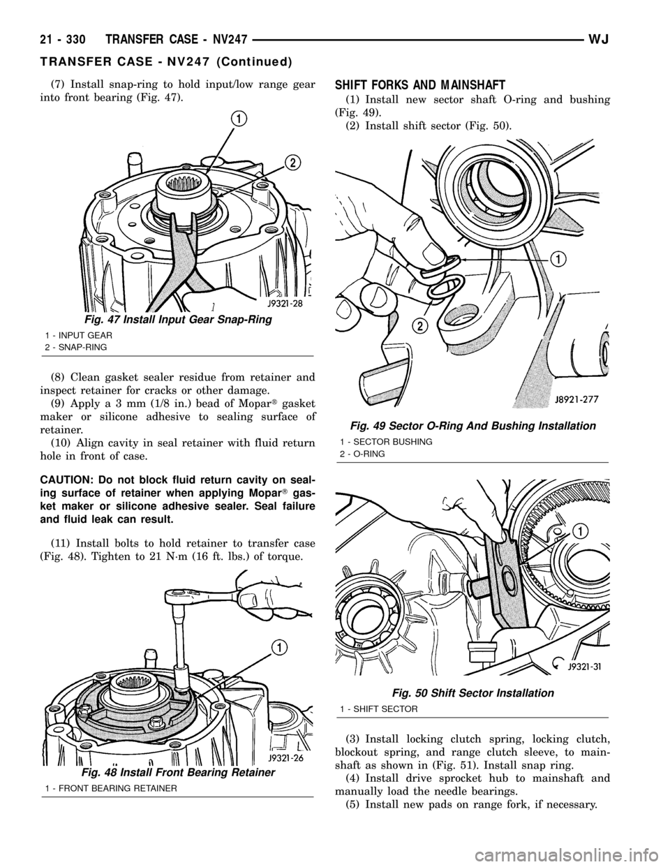
(7) Install snap-ring to hold input/low range gear
into front bearing (Fig. 47).
(8) Clean gasket sealer residue from retainer and
inspect retainer for cracks or other damage.
(9) Applya3mm(1/8 in.) bead of Mopartgasket
maker or silicone adhesive to sealing surface of
retainer.
(10) Align cavity in seal retainer with fluid return
hole in front of case.
CAUTION: Do not block fluid return cavity on seal-
ing surface of retainer when applying MoparTgas-
ket maker or silicone adhesive sealer. Seal failure
and fluid leak can result.
(11) Install bolts to hold retainer to transfer case
(Fig. 48). Tighten to 21 N´m (16 ft. lbs.) of torque.SHIFT FORKS AND MAINSHAFT
(1) Install new sector shaft O-ring and bushing
(Fig. 49).
(2) Install shift sector (Fig. 50).
(3) Install locking clutch spring, locking clutch,
blockout spring, and range clutch sleeve, to main-
shaft as shown in (Fig. 51). Install snap ring.
(4) Install drive sprocket hub to mainshaft and
manually load the needle bearings.
(5) Install new pads on range fork, if necessary.
Fig. 47 Install Input Gear Snap-Ring
1 - INPUT GEAR
2 - SNAP-RING
Fig. 48 Install Front Bearing Retainer
1 - FRONT BEARING RETAINER
Fig. 49 Sector O-Ring And Bushing Installation
1 - SECTOR BUSHING
2 - O-RING
Fig. 50 Shift Sector Installation
1 - SHIFT SECTOR
21 - 330 TRANSFER CASE - NV247WJ
TRANSFER CASE - NV247 (Continued)
Page 1855 of 2199
(6) Connect front propeller shaft and install rear
propeller shaft. (Refer to 3 - DIFFERENTIAL &
DRIVELINE/PROPELLER SHAFT/PROPELLER
SHAFT - INSTALLATION)
(7) Fill transfer case with correct fluid. Check
transmission fluid level. Correct as necessary.
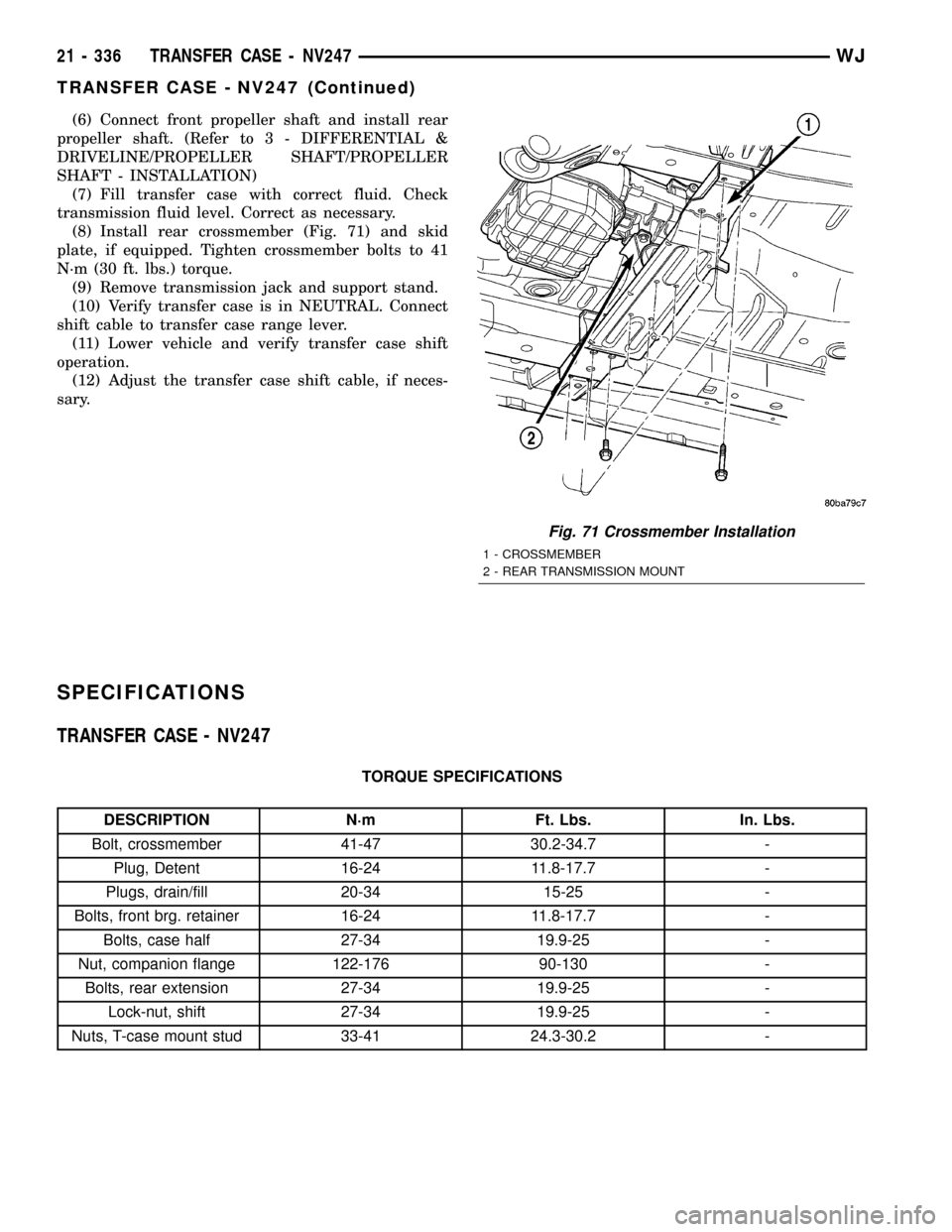
(8) Install rear crossmember (Fig. 71) and skid
plate, if equipped. Tighten crossmember bolts to 41
N´m (30 ft. lbs.) torque.
(9) Remove transmission jack and support stand.
(10) Verify transfer case is in NEUTRAL. Connect
shift cable to transfer case range lever.
(11) Lower vehicle and verify transfer case shift
operation.
(12) Adjust the transfer case shift cable, if neces-
sary.
SPECIFICATIONS
TRANSFER CASE - NV247
TORQUE SPECIFICATIONS
DESCRIPTION N´m Ft. Lbs. In. Lbs.
Bolt, crossmember 41-47 30.2-34.7 -
Plug, Detent 16-24 11.8-17.7 -
Plugs, drain/fill 20-34 15-25 -
Bolts, front brg. retainer 16-24 11.8-17.7 -
Bolts, case half 27-34 19.9-25 -
Nut, companion flange 122-176 90-130 -
Bolts, rear extension 27-34 19.9-25 -
Lock-nut, shift 27-34 19.9-25 -
Nuts, T-case mount stud 33-41 24.3-30.2 -
Fig. 71 Crossmember Installation
1 - CROSSMEMBER
2 - REAR TRANSMISSION MOUNT
21 - 336 TRANSFER CASE - NV247WJ
TRANSFER CASE - NV247 (Continued)
Page 1856 of 2199
SPECIAL TOOLS
TRANSFER CASE - NV247
Installer, Bearing - 5066
Installer, Seal - 6952-A
Installer, Bearing - 6953
Remover, Bushing - 6957
Installer, Seal - C-3995-A
Handle - C-4171
Installer, Bushing - 8145
Remover, Bearing - C-4210
Remover, Bearing - L-4454
Cup - 8148
WJTRANSFER CASE - NV247 21 - 337
TRANSFER CASE - NV247 (Continued)
Page 1858 of 2199
REAR RETAINER BUSHING
AND SEAL
REMOVAL
(1) Raise vehicle on hoist.
(2) Remove rear propeller shaft. (Refer to 3 - DIF-
FERENTIAL & DRIVELINE/PROPELLER SHAFT/
PROPELLER SHAFT - REMOVAL)
(3) Using a suitable pry tool or slide-hammer
mounted screw, remove the rear retainer seal.
(4) Using Remover 6957, remove bushing from
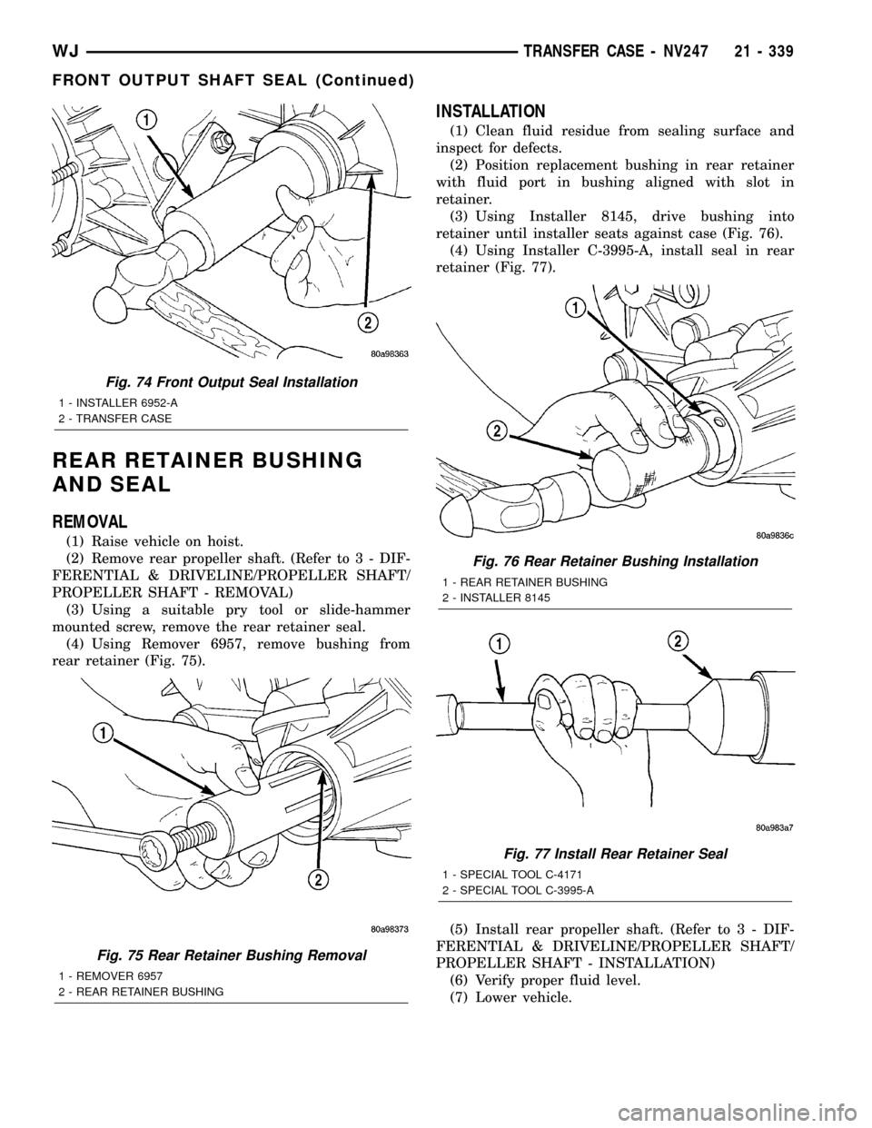
rear retainer (Fig. 75).
INSTALLATION
(1) Clean fluid residue from sealing surface and
inspect for defects.
(2) Position replacement bushing in rear retainer
with fluid port in bushing aligned with slot in
retainer.
(3) Using Installer 8145, drive bushing into
retainer until installer seats against case (Fig. 76).
(4) Using Installer C-3995-A, install seal in rear
retainer (Fig. 77).
(5) Install rear propeller shaft. (Refer to 3 - DIF-
FERENTIAL & DRIVELINE/PROPELLER SHAFT/
PROPELLER SHAFT - INSTALLATION)
(6) Verify proper fluid level.
(7) Lower vehicle.
Fig. 74 Front Output Seal Installation
1 - INSTALLER 6952-A
2 - TRANSFER CASE
Fig. 75 Rear Retainer Bushing Removal
1 - REMOVER 6957
2 - REAR RETAINER BUSHING
Fig. 76 Rear Retainer Bushing Installation
1 - REAR RETAINER BUSHING
2 - INSTALLER 8145
Fig. 77 Install Rear Retainer Seal
1 - SPECIAL TOOL C-4171
2 - SPECIAL TOOL C-3995-A
WJTRANSFER CASE - NV247 21 - 339
FRONT OUTPUT SHAFT SEAL (Continued)
Page 1860 of 2199
TIRES/WHEELS
TABLE OF CONTENTS
page page
TIRES/WHEELS
DIAGNOSIS AND TESTING - TIRE AND
WHEEL RUNOUT......................1
STANDARD PROCEDURE
STANDARD PROCEDURE - TIRE AND
WHEEL BALANCE......................2
STANDARD PROCEDURE - MATCH
MOUNTING...........................4
STANDARD PROCEDURE - TIRE ROTATION . 5
STANDARD PROCEDURE - WHEEL
INSTALLATION........................5
TIRES
DESCRIPTION
DESCRIPTION - TIRES..................6
DESCRIPTION - RADIAL±PLY TIRES.......6
DESCRIPTION - TIRE INFLATION
PRESSURES..........................6
DESCRIPTION - TIRE PRESSURE FOR
HIGH SPEED..........................7
DESCRIPTION - REPLACEMENT TIRES.....7
DIAGNOSIS AND TESTING
DIAGNOSIS AND TESTING - PRESSURE
GAUGES.............................8
DIAGNOSIS AND TESTING - TREAD WEAR
INDICATORS..........................8
DIAGNOSIS AND TESTING - TIRE WEAR
PATTERNS...........................8
DIAGNOSIS AND TESTING - TIRE NOISE
OR VIBRATION........................8STANDARD PROCEDURE - REPAIRING
LEAKS...............................8
CLEANING.............................9
SPECIFICATIONS
TIRES...............................9
SPECIFICATIONS -.....................9
SPARE TIRE
DESCRIPTION - SPARE / TEMPORARY TIRE . . 10
WHEELS
DESCRIPTION.........................10
DIAGNOSIS AND TESTING - WHEEL
INSPECTION.........................10
STANDARD PROCEDURE - WHEEL
REPLACEMENT.......................10
SPECIFICATIONS
TORQUE CHART......................11
STUDS
REMOVAL.............................11
INSTALLATION.........................11
TIRE PRESSURE MONITORING
DESCRIPTION.........................12
OPERATION...........................12
DIAGNOSIS AND TESTING - TIRE PRESSURE
MONITORING SYSTEM.................12
SENSOR
REMOVAL - TIRE PRESSURE SENSOR/
TRANSMITTER.......................12
INSTALLATION - TIRE PRESSURE SENSOR/
TRANSMITTER.......................13
TIRES/WHEELS
DIAGNOSIS AND TESTING - TIRE AND WHEEL
RUNOUT
Radial runout is the difference between the high
and low points on the tire or wheel (Fig. 1).
Lateral runout is thewobbleof the tire or wheel.
Radial runout of more than 1.5 mm (.060 inch)
measured at the center line of the tread may cause
the vehicle to shake.
Lateral runout of more than 2.0 mm (.080 inch)
measured near the shoulder of the tire may cause the
vehicle to shake.
Sometimes radial runout can be reduced. Relocate
the wheel and tire assembly on the mounting studs
(See Method 1). If this does not reduce runout to an
acceptable level, the tire can be rotated on the wheel.
(See Method 2).
METHOD 1 (RELOCATE WHEEL ON HUB)
(1) Drive vehicle a short distance to eliminate tire
flat spotting from a parked position.
(2) Check wheel bearings and adjust if adjustable
or replace if necessary.
(3) Check the wheel mounting surface.
(4) Relocate wheel on the mounting, two studs
over from the original position.
(5) Tighten wheel nuts until all are properly
torqued, to eliminate brake distortion.
(6) Check radial runout. If still excessive, mark
tire sidewall, wheel, and stud at point of maximum
runout and proceed to Method 2.
METHOD 2 (RELOCATE TIRE ON WHEEL)
NOTE: Rotating the tire on wheel is particularly
effective when there is runout in both tire and
wheel.
WJTIRES/WHEELS 22 - 1