2003 JEEP GRAND CHEROKEE Wheel bearing
[x] Cancel search: Wheel bearingPage 208 of 2199
STANDARD PROCEDURE - DISC ROTOR
MACHINING
CAUTION: For vehicles equipped with the Quadra-
Drive System, consisting of the NV-247 transfer case
and a Vari-Lok differential in the front and rear axles,
the following steps must be done prior to the use of a
hub mounted on-vehicle brake lathe. Disconnect the
driveshaft (Refer to 3 - DIFFERENTIAL & DRIVELINE/
PROPELLER SHAFT/PROPELLER SHAFT - REMOVAL)
from the respective axle on which the brake rotors are
being machined. Temporarily remove both brake cali-
pers (Refer to 5 - BRAKES/HYDRAULIC/MECHANICAL/
DISC BRAKE CALIPERS - REMOVAL) from the axle
while disc rotor machining is in process. Both steps
will prevent unnecessary loads to the hub mounted
on-vehicle lathe and speed machining times. Install a
thread lock material to the driveshaft attaching bolts
when reinstalling (Refer to 3 - DIFFERENTIAL & DRIV-
ELINE/PROPELLER SHAFT/PROPELLER SHAFT -
INSTALLATION).
NOTE: A hub mounted on-vehicle lathe is recom-
mended. This type of lathe trues the rotor to the vehi-
cles hub/bearing.
The disc brake rotor can be machined if scored or
worn. The lathe must machine both sides of the rotor
simultaneously with dual cutter heads. The rotor
mounting surface must be clean before placing on the
lathe. Equipment capable of machining only one side at
a time may produce a tapered rotor.
CAUTION: Brake rotors that do not meet minimum
thickness specifications before or after machining
must be replaced.
REMOVAL
REMOVAL - FRONT DISC BRAKE ROTOR
NOTE: Front rotors and hub/bearings are matched
mounted for minimum lateral runout. Before removing
the rotor, mark the rotor and hub/bearing to maintain
original orientation.
(1) Raise and support the vehicle.
(2) Remove wheel and tire assembly.
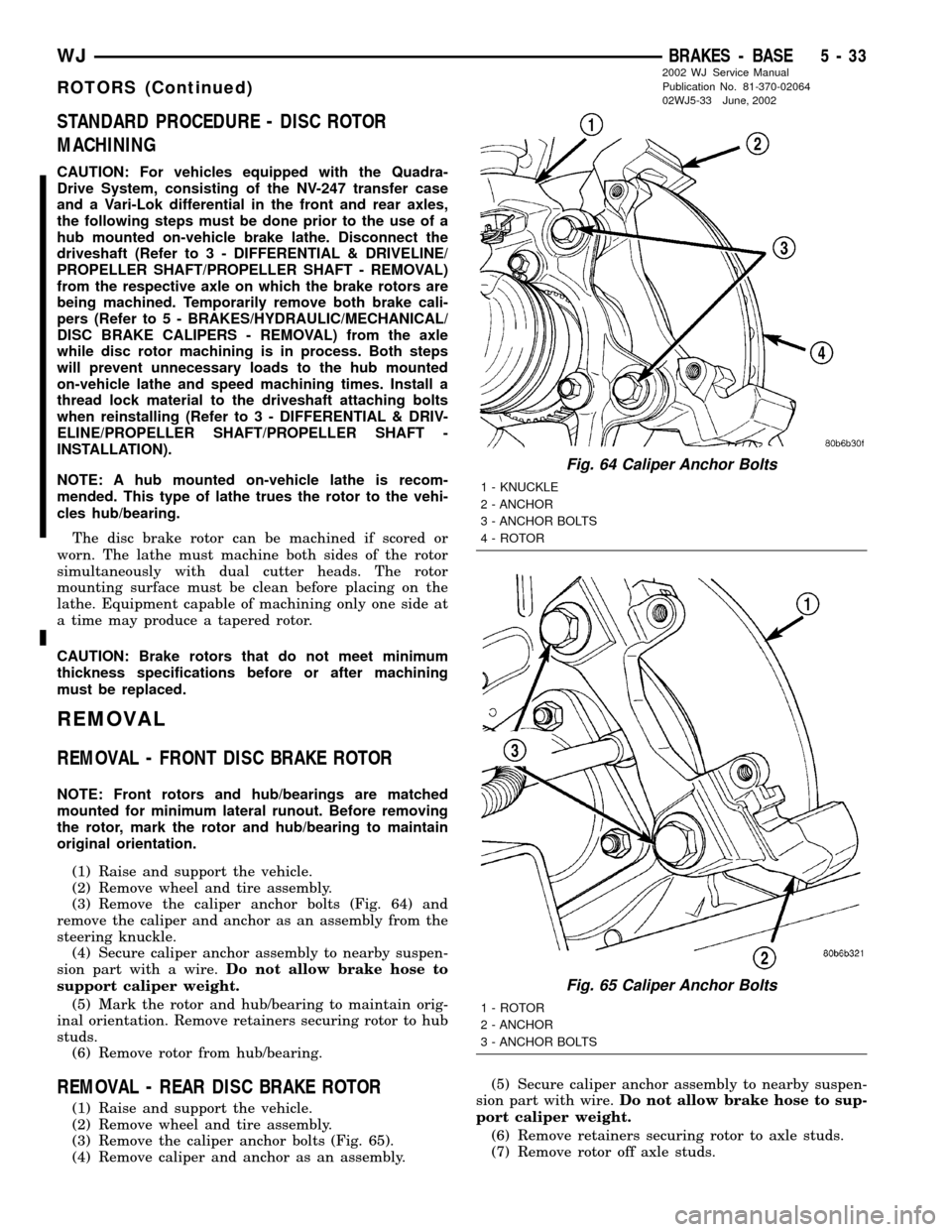
(3) Remove the caliper anchor bolts (Fig. 64) and
remove the caliper and anchor as an assembly from the
steering knuckle.
(4) Secure caliper anchor assembly to nearby suspen-
sion part with a wire.Do not allow brake hose to
support caliper weight.
(5) Mark the rotor and hub/bearing to maintain orig-
inal orientation. Remove retainers securing rotor to hub
studs.
(6) Remove rotor from hub/bearing.
REMOVAL - REAR DISC BRAKE ROTOR
(1) Raise and support the vehicle.
(2) Remove wheel and tire assembly.
(3) Remove the caliper anchor bolts (Fig. 65).
(4) Remove caliper and anchor as an assembly.(5) Secure caliper anchor assembly to nearby suspen-
sion part with wire.Do not allow brake hose to sup-
port caliper weight.
(6) Remove retainers securing rotor to axle studs.
(7) Remove rotor off axle studs.
Fig. 64 Caliper Anchor Bolts
1 - KNUCKLE
2 - ANCHOR
3 - ANCHOR BOLTS
4 - ROTOR
Fig. 65 Caliper Anchor Bolts
1 - ROTOR
2 - ANCHOR
3 - ANCHOR BOLTS
WJBRAKES - BASE 5 - 33
ROTORS (Continued)
2002 WJ Service Manual
Publication No. 81-370-02064
02WJ5-33 June, 2002
Page 209 of 2199

INSTALLATION
INSTALLATION - FRONT DISC BRAKE ROTOR
NOTE: If a new rotor is installed it must be match
mounted to the hub/bearing.
(1) Install rotor on hub studs in its original loca-
tion.
(2) Install the caliper anchor assembly on the
knuckle. Install anchor bolts and tighten to 90-115
N´m (66-85 ft. lbs.).
(3) Install wheel and tire assembly.
(4) Remove support and lower the vehicle.
(5) Pump brake pedal to seat caliper pistons and
brake shoes. Do not move vehicle until firm brake
pedal is obtained.
INSTALLATION - REAR DISC BRAKE ROTOR
(1) Install rotor on axle studs.
(2) Install the caliper anchor assembly.
(3) Install anchor bolts and tighten to 90-115 N´m
(66-85 ft. lbs.).
(4) Install wheel and tire assembly.
(5) Remove support and lower the vehicle.
(6) Pump brake pedal until caliper pistons and
brake shoes are seated.
PARKING BRAKE
OPERATION
The parking brakes operated by a automatic ten-
sioner mechanism built into the hand lever and cable
system. The front cable is connected to the hand
lever and the equalizer. The rear cables attached to
the equalizer and the parking brake shoe actuator.
A set of drum type brake shoes are used for park-
ing brakes. The shoes are mounted to the rear disc
brake adaptor. The parking brake drum is integrated
into the rear disc brake rotor.
Parking brake cable adjustment is controlled by an
automatic tensioner mechanism. The only adjust-
ment if necessary is to the park brake shoes if the
linings are worn.
DIAGNOSIS AND TESTING - PARKING BRAKE
NOTE: Parking brake adjustment is controlled by an
automatic cable tensioner and does not require
adjustment. The only adjustment that may be nec-
essary would be to the park brake shoes if they are
worn.
The parking brake switch is in circuit with the red
warning lamp in the dash. The switch will cause the
lamp to illuminate only when the parking brakes are
applied. If the lamp remains on after parking brake
release, the switch or wires are faulty.
If the red lamp comes on a fault has occurred in
the front or rear brake hydraulic system.
If the red warning lamp and yellow warning lamp
come on, the electronic brake distribution may be at
fault.
In most cases, the actual cause of an improperly
functioning parking brake (too loose/too tight/won't
hold), can be traced to a parking brake component.
NOTE: The leading cause of improper parking brake
operation, is excessive clearance between the park-
ing brake shoes and the shoe braking surface.
Excessive clearance is a result of lining and/or
drum wear, drum surface machined oversize.
Excessive parking brake lever travel (sometimes
described as a loose lever or too loose condition), is
the result of worn brake shoes, improper brake shoe
adjustment, or improperly assembled brake parts.
A too loose condition can also be caused by inoper-
ative or improperly assembled parking brake shoe
parts.
A condition where the parking brakes do not hold,
will most probably be due to a wheel brake compo-
nent.
Items to look for when diagnosing a parking brake
problem, are:
²Brake shoe wear
²Drum surface (in rear rotor) machined oversize
²Front cable not secured to lever
²Rear cable not attached to actuator
²Rear cable seized
²Parking brake lever not seated
²Parking brake lever bind
5 - 34 BRAKES - BASEWJ
ROTORS (Continued)
Page 263 of 2199

FAN DRIVE VISCOUS CLUTCH
- 4.0L
DESCRIPTION
CAUTION: Engines equipped with serpentine drive
belts have reverse rotating fans and viscous fan
drives. They are marked with the word REVERSE to
designate their usage. Installation of the wrong fan
or viscous fan drive can result in engine overheat-
ing.
CAUTION: If the viscous fan drive is replaced
because of mechanical damage, the cooling fan
blades should also be inspected. Inspect for fatigue
cracks, loose blades, or loose rivets that could
have resulted from excessive vibration. Replace fan
blade assembly if any of these conditions are
found. Also inspect water pump bearing and shaft
assembly for any related damage due to a viscous
fan drive malfunction.
The thermal viscous fan drive (Fig. 27) is a sili-
cone-fluid-filled coupling used to connect the fan
blades to the water pump shaft. The coupling allows
the fan to be driven in a normal manner. This is
done at low engine speeds while limiting the top
speed of the fan to a predetermined maximum level
at higher engine speeds.
An electrical cooling fan located in the fan shroud
aids in low speed cooling, It is designed to augment
the viscous fan, However, it does not replace the vis-
cous fan.
OPERATION
A thermostatic bimetallic spring coil is located on
the front face of the viscous fan drive unit (Fig. 27).
This spring coil reacts to the temperature of the radi-
ator discharge air. It engages the viscous fan drive
for higher fan speed if the air temperature from the
radiator rises above a certain point. Until additional
engine cooling is necessary,the fan will remain at
a reduced rpm regardless of engine speed. Nor-
mally less than three hundred (300) rpm.
Only when sufficient heat is present, will the vis-
cous fan drive engage. This is when the air flowing
through the radiator core causes a reaction to the
bimetallic coil. It then increases fan speed to provide
the necessary additional engine cooling.
Once the engine has cooled, the radiator discharge
temperature will drop. The bimetallic coil again
reacts and the fan speed is reduced to the previous
disengaged speed.
DIAGNOSIS AND TESTINGÐVISCOUS FAN
DRIVE
If the fan assembly free-wheels without drag (the
fan blades will revolve more than five turns when
spun by hand), replace the fan drive. This spin test
must be performed when the engine is cool.
For the following test, the cooling system must be
in good condition. It also will ensure against exces-
sively high coolant temperature.
WARNING: BE SURE THAT THERE IS ADEQUATE
FAN BLADE CLEARANCE BEFORE DRILLING.
(1) Drill a 3.18-mm (1/8-in) diameter hole in the
top center of the fan shroud.
(2) Obtain a dial thermometer with an 8 inch stem
(or equivalent). It should have a range of -18É to
105ÉC (0É to 220É F). Insert thermometer through the
hole in the shroud. Be sure that there is adequate
clearance from the fan blades.
(3) Connect a tachometer and an engine ignition
timing light (timing light is to be used as a strobe
light).
(4) Block the air flow through the radiator. Secure
a sheet of plastic in front of the radiator (or air con-
ditioner condenser). Use tape at the top to secure the
plastic and be sure that the air flow is blocked.
(5) Be sure that the air conditioner (if equipped) is
turned off.
WARNING: USE EXTREME CAUTION WHEN THE
ENGINE IS OPERATING. DO NOT STAND IN A
DIRECT LINE WITH THE FAN. DO NOT PUT YOUR
HANDS NEAR THE PULLEYS, BELTS OR FAN. DO
NOT WEAR LOOSE CLOTHING.
Fig. 27 Viscous Fan Drive
1 - VISCOUS FAN DRIVE
2 - THERMOSTATIC SPRING
3 - MOUNTING NUT TO WATER PUMP HUB
7 - 40 ENGINEWJ
Page 1250 of 2199
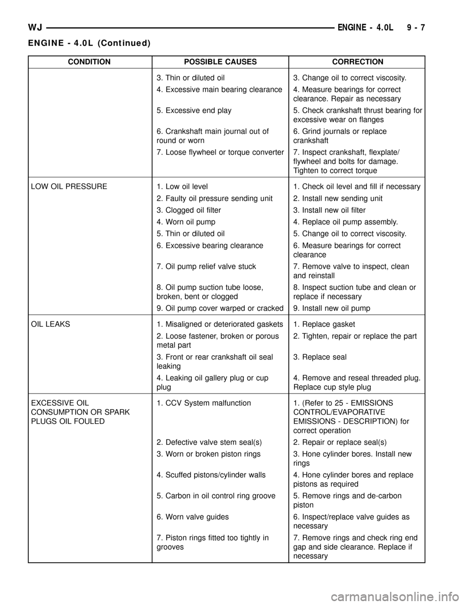
CONDITION POSSIBLE CAUSES CORRECTION
3. Thin or diluted oil 3. Change oil to correct viscosity.
4. Excessive main bearing clearance 4. Measure bearings for correct
clearance. Repair as necessary
5. Excessive end play 5. Check crankshaft thrust bearing for
excessive wear on flanges
6. Crankshaft main journal out of
round or worn6. Grind journals or replace
crankshaft
7. Loose flywheel or torque converter 7. Inspect crankshaft, flexplate/
flywheel and bolts for damage.
Tighten to correct torque
LOW OIL PRESSURE 1. Low oil level 1. Check oil level and fill if necessary
2. Faulty oil pressure sending unit 2. Install new sending unit
3. Clogged oil filter 3. Install new oil filter
4. Worn oil pump 4. Replace oil pump assembly.
5. Thin or diluted oil 5. Change oil to correct viscosity.
6. Excessive bearing clearance 6. Measure bearings for correct
clearance
7. Oil pump relief valve stuck 7. Remove valve to inspect, clean
and reinstall
8. Oil pump suction tube loose,
broken, bent or clogged8. Inspect suction tube and clean or
replace if necessary
9. Oil pump cover warped or cracked 9. Install new oil pump
OIL LEAKS 1. Misaligned or deteriorated gaskets 1. Replace gasket
2. Loose fastener, broken or porous
metal part2. Tighten, repair or replace the part
3. Front or rear crankshaft oil seal
leaking3. Replace seal
4. Leaking oil gallery plug or cup
plug4. Remove and reseal threaded plug.
Replace cup style plug
EXCESSIVE OIL
CONSUMPTION OR SPARK
PLUGS OIL FOULED1. CCV System malfunction 1. (Refer to 25 - EMISSIONS
CONTROL/EVAPORATIVE
EMISSIONS - DESCRIPTION) for
correct operation
2. Defective valve stem seal(s) 2. Repair or replace seal(s)
3. Worn or broken piston rings 3. Hone cylinder bores. Install new
rings
4. Scuffed pistons/cylinder walls 4. Hone cylinder bores and replace
pistons as required
5. Carbon in oil control ring groove 5. Remove rings and de-carbon
piston
6. Worn valve guides 6. Inspect/replace valve guides as
necessary
7. Piston rings fitted too tightly in
grooves7. Remove rings and check ring end
gap and side clearance. Replace if
necessary
WJENGINE - 4.0L 9 - 7
ENGINE - 4.0L (Continued)
Page 1261 of 2199
DESCRIPTION N´m Ft. In.
Lbs. Lbs.
Transmission Support Bracket
ÐBolt (Manual) 46 34 Ð
Transmission Support Bracket/
CushionÐBolt (4WD Auto) 75 55 Ð
Transmission Support Adaptor
BracketÐBolts (2WD Auto) 75 55 Ð
Exhaust Manifold/PipeÐNuts 27 20 Ð
Intake/Exhaust Manifold
Fasteners #1-5 33 24 Ð
Fasteners #6 and 7 14 Ð 126
Fasteners #8-11 33 24 Ð
Flywheel to Converter
HousingÐBolts38 28 Ð
Flywheel to CrankshaftÐBolts 143 105 Ð
Front Cover to BlockÐBolts
1/4-20 7 Ð 60
5/16-18 22 Ð 192
Fuel RailÐBolts/Stud 12 Ð 108
GeneratorÐBolts 57 42 Ð
Generator Bracket to EngineÐ
Bolts47 35 Ð
Idler Pulley to Cylinder
HeadÐBolt47 35 Ð
Main Bearing CapÐBolts 108 80 Ð
Oil Filter 18 Ð 156
Oil Filter Connector to
Adaptor 47 35 Ð
Block 68 50 Ð
Adaptor Bolts 102 50 Ð
Oil GalleyÐPlug 41 30 Ð
Oil PanÐBolts
1/4-20 9.5 Ð 84
5/16-18 15 Ð 132
Oil PanÐDrain Plug 34 25 Ð
Oil Pump
Mounting Bolts 23 Ð 204
Cover Bolts 8 Ð 70
Rocker Arm Assembly to
Cylinder
HeadÐCapscrews 30 21 Ð
Spark Plugs 37 27 ÐDESCRIPTION N´m Ft. In.
Lbs. Lbs.
Starter MotorÐMounting Bolts 45 33 Ð
Thermostat HousingÐBolts 18 Ð 156
Throttle BodyÐBolts 10 Ð 90
Vibration DamperÐBolt 108 80 Ð
Water Pump to BlockÐBolts 23 17 Ð
AIR CLEANER ELEMENT
REMOVAL - 4.0L
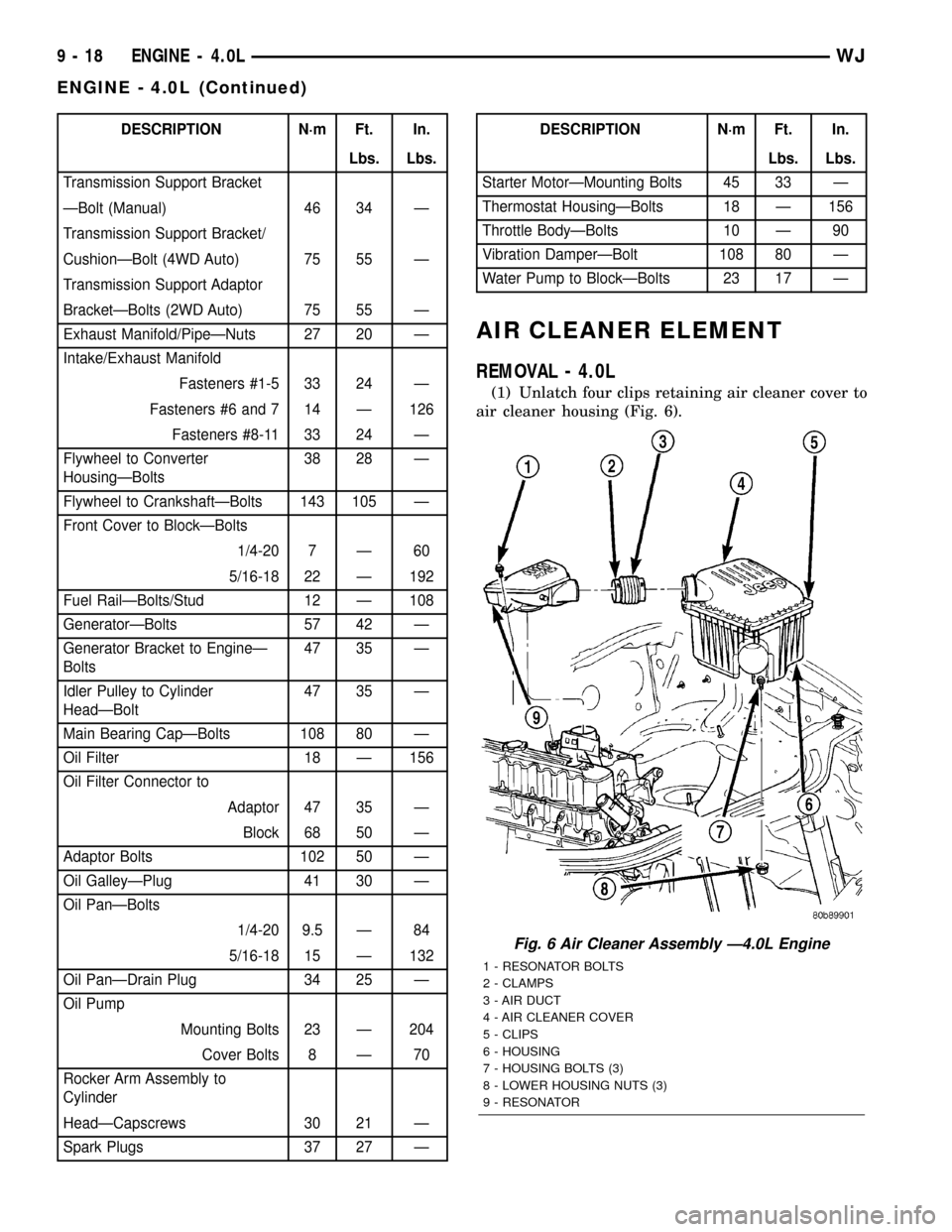
(1) Unlatch four clips retaining air cleaner cover to
air cleaner housing (Fig. 6).
Fig. 6 Air Cleaner Assembly Ð4.0L Engine
1 - RESONATOR BOLTS
2 - CLAMPS
3 - AIR DUCT
4 - AIR CLEANER COVER
5 - CLIPS
6 - HOUSING
7 - HOUSING BOLTS (3)
8 - LOWER HOUSING NUTS (3)
9 - RESONATOR
9 - 18 ENGINE - 4.0LWJ
ENGINE - 4.0L (Continued)
Page 1299 of 2199
(9) Lower the engine until it is properly located on
the engine mounts.
(10) Install the through bolts and tighten the nuts.
(11) Lower the jack stand and remove the piece of
wood.
(12) Install the engine flywheel and transmission
torque converter housing access cover.
(13) Install the engine starter motor. (Refer to 8 -
ELECTRICAL/STARTING/STARTER MOTOR -
INSTALLATION).
(14) Connect the exhaust pipe to the hanger and to
the engine exhaust manifold.
(15) Install transmission oil cooling lines (if
equipped) and oxygen sensor wiring supports that
attach to the oil pan studs.
(16) Install the oil pan drain plug (Fig. 81).
Tighten the plug to 34 N´m (25 ft. lbs.) torque.
(17) Lower the vehicle.
(18) Connect negative cable to battery.
(19) Fill the oil pan with engine oil to the specified
level.
WARNING: USE EXTREME CAUTION WHEN THE
ENGINE IS OPERATING. DO NOT STAND IN A
DIRECT LINE WITH THE FAN. DO NOT PUT YOUR
HANDS NEAR THE PULLEYS, BELTS OR FAN. DO
NOT WEAR LOOSE CLOTHING.
(20) Start the engine and inspect for leaks.
ENGINE OIL PRESSURE
SENSOR
DESCRIPTION
The 3±wire, solid-state engine oil pressure sensor
(sending unit) is located in an engine oil pressure
gallery.
OPERATION
The oil pressure sensor uses three circuits. They
are:
²A 5±volt power supply from the Powertrain Con-
trol Module (PCM)
²A sensor ground through the PCM's sensor
return
²A signal to the PCM relating to engine oil pres-
sure
The oil pressure sensor has a 3±wire electrical
function very much like the Manifold Absolute Pres-
sure (MAP) sensor. Meaning different pressures
relate to different output voltages.
A 5±volt supply is sent to the sensor from the PCM
to power up the sensor. The sensor returns a voltage
signal back to the PCM relating to engine oil pres-
sure. This signal is then transferred (bussed) to theinstrument panel on either a CCD or PCI bus circuit
(depending on vehicle line) to operate the oil pressure
gauge and the check gauges lamp. Ground for the
sensor is provided by the PCM through a low-noise
sensor return.
OIL PUMP
REMOVAL
A gear-type oil pump is mounted at the underside
of the cylinder block opposite the No.4 main bearing.
(1) Drain the engine oil.
(2) Remove the oil pan (Refer to 9 - ENGINE/LU-
BRICATION/OIL PAN - REMOVAL).
(3) Remove the pump-to-cylinder block attaching
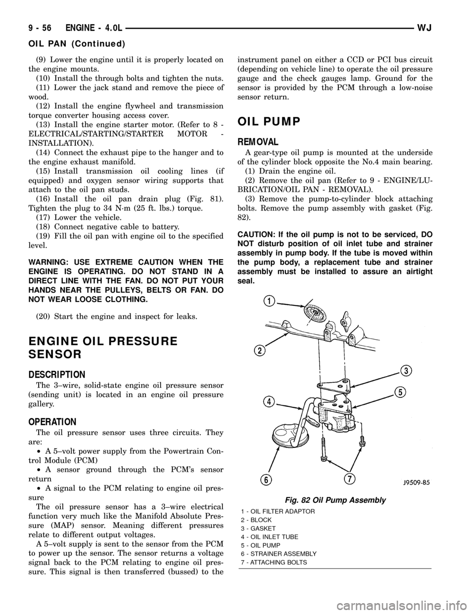
bolts. Remove the pump assembly with gasket (Fig.
82).
CAUTION: If the oil pump is not to be serviced, DO
NOT disturb position of oil inlet tube and strainer
assembly in pump body. If the tube is moved within
the pump body, a replacement tube and strainer
assembly must be installed to assure an airtight
seal.
Fig. 82 Oil Pump Assembly
1 - OIL FILTER ADAPTOR
2 - BLOCK
3 - GASKET
4 - OIL INLET TUBE
5 - OIL PUMP
6 - STRAINER ASSEMBLY
7 - ATTACHING BOLTS
9 - 56 ENGINE - 4.0LWJ
OIL PAN (Continued)
Page 1310 of 2199
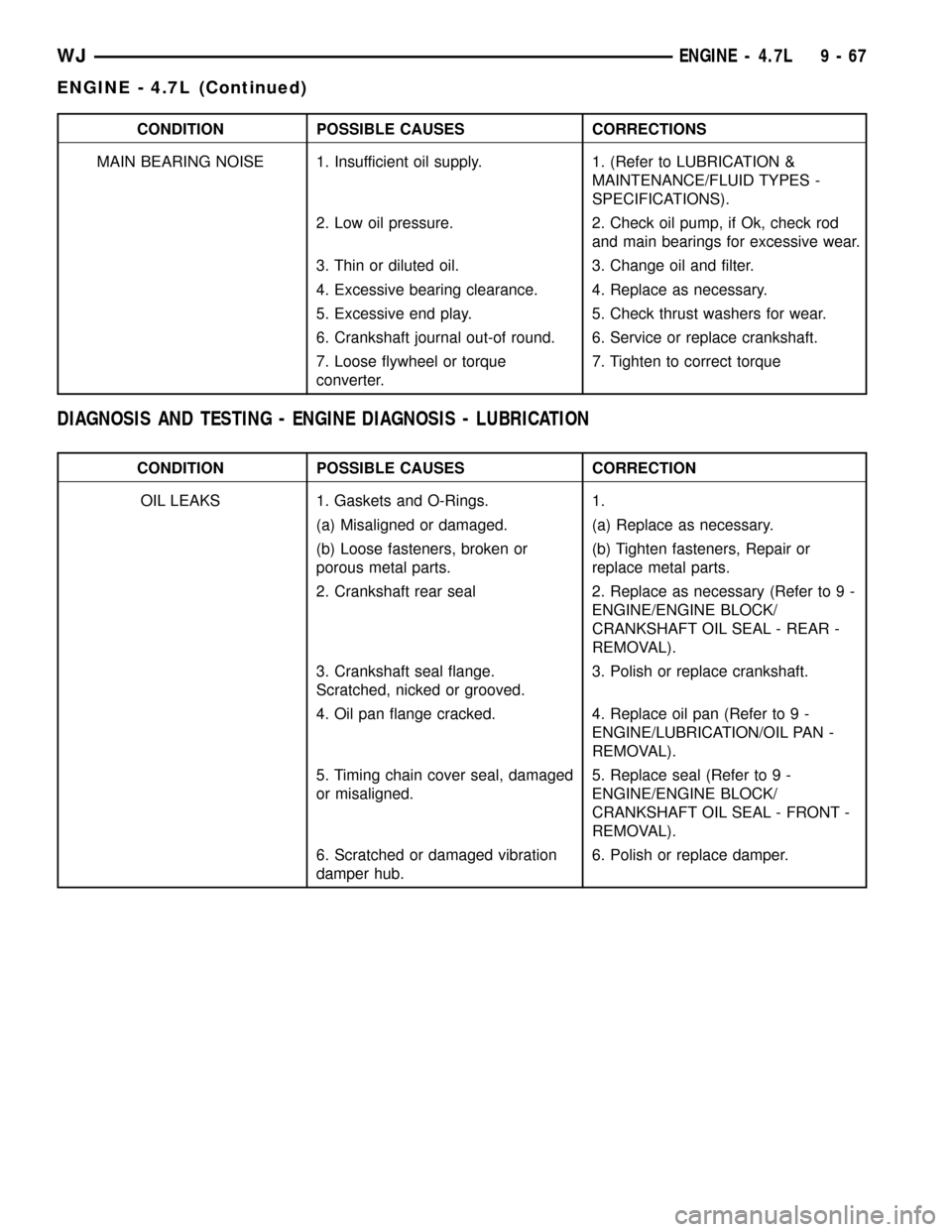
CONDITION POSSIBLE CAUSES CORRECTIONS
MAIN BEARING NOISE 1. Insufficient oil supply. 1. (Refer to LUBRICATION &
MAINTENANCE/FLUID TYPES -
SPECIFICATIONS).
2. Low oil pressure. 2. Check oil pump, if Ok, check rod
and main bearings for excessive wear.
3. Thin or diluted oil. 3. Change oil and filter.
4. Excessive bearing clearance. 4. Replace as necessary.
5. Excessive end play. 5. Check thrust washers for wear.
6. Crankshaft journal out-of round. 6. Service or replace crankshaft.
7. Loose flywheel or torque
converter.7. Tighten to correct torque
DIAGNOSIS AND TESTING - ENGINE DIAGNOSIS - LUBRICATION
CONDITION POSSIBLE CAUSES CORRECTION
OIL LEAKS 1. Gaskets and O-Rings. 1.
(a) Misaligned or damaged. (a) Replace as necessary.
(b) Loose fasteners, broken or
porous metal parts.(b) Tighten fasteners, Repair or
replace metal parts.
2. Crankshaft rear seal 2. Replace as necessary (Refer to 9 -
ENGINE/ENGINE BLOCK/
CRANKSHAFT OIL SEAL - REAR -
REMOVAL).
3. Crankshaft seal flange.
Scratched, nicked or grooved.3. Polish or replace crankshaft.
4. Oil pan flange cracked. 4. Replace oil pan (Refer to 9 -
ENGINE/LUBRICATION/OIL PAN -
REMOVAL).
5. Timing chain cover seal, damaged
or misaligned.5. Replace seal (Refer to 9 -
ENGINE/ENGINE BLOCK/
CRANKSHAFT OIL SEAL - FRONT -
REMOVAL).
6. Scratched or damaged vibration
damper hub.6. Polish or replace damper.
WJENGINE - 4.7L 9 - 67
ENGINE - 4.7L (Continued)
Page 1343 of 2199
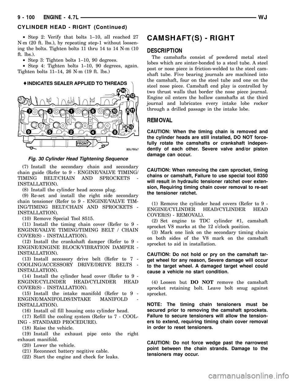
²Step 2: Verify that bolts 1±10, all reached 27
N´m (20 ft. lbs.), by repeating step-1 without loosen-
ing the bolts. Tighten bolts 11 thru 14 to 14 N´m (10
ft. lbs.).
²Step 3: Tighten bolts 1±10, 90 degrees.
²Step 4: Tighten bolts 1±10, 90 degrees, again.
Tighten bolts 11±14, 26 N´m (19 ft. lbs.)
(7) Install the secondary chain and secondary
chain guide (Refer to 9 - ENGINE/VALVE TIMING/
TIMING BELT/CHAIN AND SPROCKETS -
INSTALLATION).
(8) Install the cylinder head access plug.
(9) Re-set and install the right side secondary
chain tensioner (Refer to 9 - ENGINE/VALVE TIM-
ING/TIMING BELT/CHAIN AND SPROCKETS -
INSTALLATION).
(10) Remove Special Tool 8515.
(11) Install the timing chain cover (Refer to 9 -
ENGINE/VALVE TIMING/TIMING BELT / CHAIN
COVER(S) - INSTALLATION).
(12) Install the crankshaft damper (Refer to 9 -
ENGINE/ENGINE BLOCK/VIBRATION DAMPER -
INSTALLATION).
(13) Install accessory drive belt (Refer to 7 -
COOLING/ACCESSORY DRIVE/DRIVE BELTS -
INSTALLATION).
(14) Install the cylinder head cover (Refer to 9 -
ENGINE/CYLINDER HEAD/CYLINDER HEAD
COVER(S) - INSTALLATION).
(15) Install the intake manifold (Refer to 9 -
ENGINE/MANIFOLDS/INTAKE MANIFOLD -
INSTALLATION).
(16) Install oil fill housing onto cylinder head.
(17) Refill the cooling system (Refer to 7 - COOL-
ING - STANDARD PROCEDURE).
(18) Raise the vehicle.
(19) Install the exhaust pipe onto the right
exhaust manifold.
(20) Lower the vehicle.
(21) Reconnect battery negitive cable.
(22) Start the engine and check for leaks.CAMSHAFT(S) - RIGHT
DESCRIPTION
The camshafts consist of powdered metal steel
lobes which are sinter-bonded to a steel tube. A steel
post or nose piece is friction-welded to the steel cam-
shaft tube. Five bearing journals are machined into
the camshaft, four on the steel tube and one on the
steel nose piece. Camshaft end play is controlled by
two thrust walls that border the nose piece journal.
Engine oil enters the hollow camshafts at the third
journal and lubricates every intake lobe rocker
through a drilled passage in the intake lobe.
REMOVAL
CAUTION: When the timing chain is removed and
the cylinder heads are still installed, DO NOT force-
fully rotate the camshafts or crankshaft indepen-
dently of each other. Severe valve and/or piston
damage can occur.
CAUTION: When removing the cam sprocket, timing
chains or camshaft, Failure to use special tool 8350
will result in hydraulic tensioner ratchet over exten-
sion, Requiring timing chain cover removal to re-set
the tensioner ratchet.
(1) Remove the cylinder head covers (Refer to 9 -
ENGINE/CYLINDER HEAD/CYLINDER HEAD
COVER(S) - REMOVAL).
(2) Set engine to TDC cylinder #1, camshaft
sprocket V8 marks at the 12 o'clock position.
(3) Mark one link on the secondary timing chain
on both sides of the V8 mark on the camshaft
sprocket to aid in installation.
CAUTION: Do not hold or pry on the camshaft tar-
get wheel for any reason, Severe damage will occur
to the target wheel. A damaged target wheel could
cause a vehicle no start condition.
(4) Loosen butDO NOTremove the camshaft
sprocket retaining bolt. Leave bolt snug against
sprocket.
NOTE: The timing chain tensioners must be
secured prior to removing the camshaft sprockets.
Failure to secure tensioners will allow the tension-
ers to extend, requiring timing chain cover removal
in order to reset tensioners.
CAUTION: Do not force wedge past the narrowest
point between the chain strands. Damage to the
tensioners may occur.
Fig. 30 Cylinder Head Tightening Sequence
9 - 100 ENGINE - 4.7LWJ
CYLINDER HEAD - RIGHT (Continued)