2003 JEEP GRAND CHEROKEE VACUUM LINE
[x] Cancel search: VACUUM LINEPage 2132 of 2199
equipment manufacturer for proper care and use of
this equipment.
A manifold gauge set may be needed with some
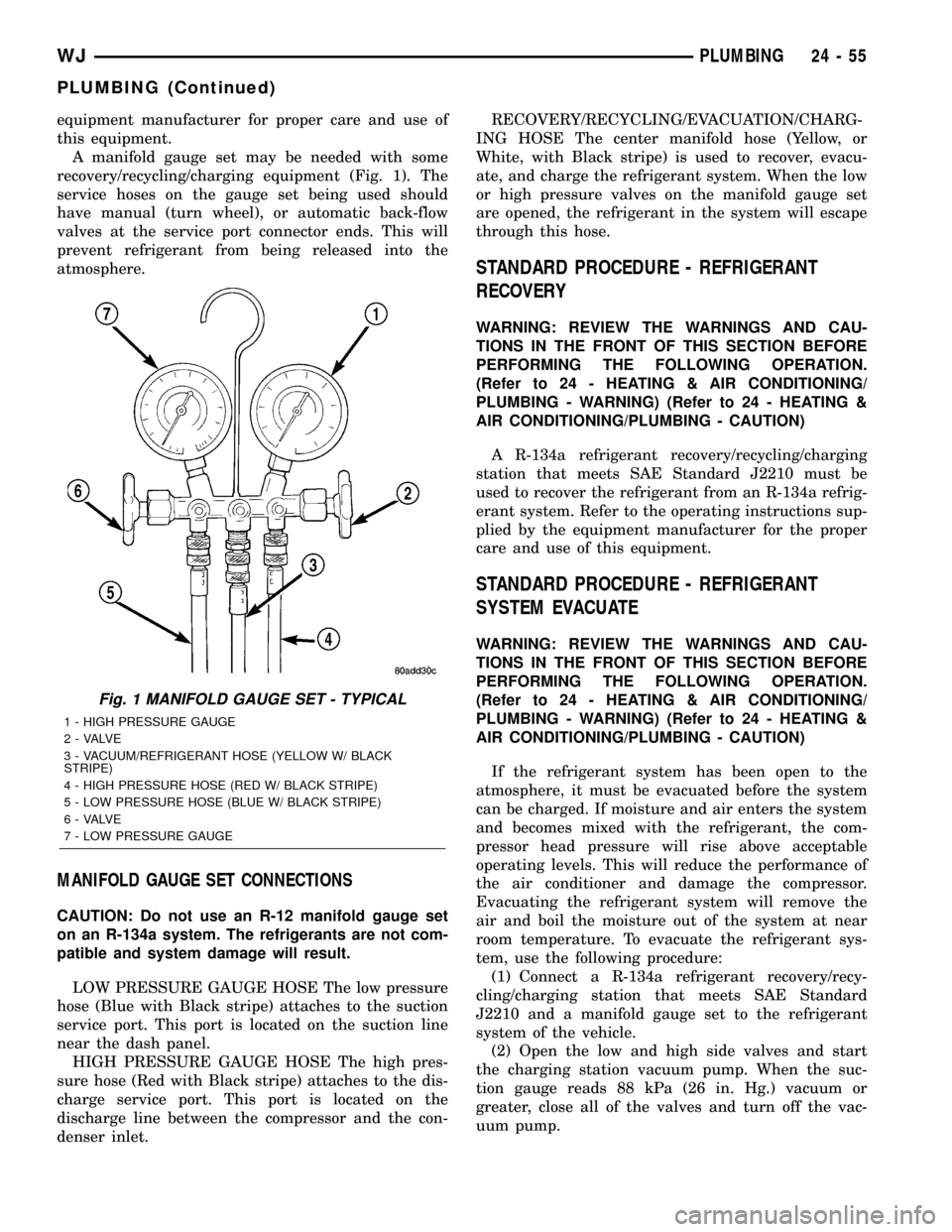
recovery/recycling/charging equipment (Fig. 1). The
service hoses on the gauge set being used should
have manual (turn wheel), or automatic back-flow
valves at the service port connector ends. This will
prevent refrigerant from being released into the
atmosphere.
MANIFOLD GAUGE SET CONNECTIONS
CAUTION: Do not use an R-12 manifold gauge set
on an R-134a system. The refrigerants are not com-
patible and system damage will result.
LOW PRESSURE GAUGE HOSE The low pressure
hose (Blue with Black stripe) attaches to the suction
service port. This port is located on the suction line
near the dash panel.
HIGH PRESSURE GAUGE HOSE The high pres-
sure hose (Red with Black stripe) attaches to the dis-
charge service port. This port is located on the
discharge line between the compressor and the con-
denser inlet.RECOVERY/RECYCLING/EVACUATION/CHARG-
ING HOSE The center manifold hose (Yellow, or
White, with Black stripe) is used to recover, evacu-
ate, and charge the refrigerant system. When the low
or high pressure valves on the manifold gauge set
are opened, the refrigerant in the system will escape
through this hose.
STANDARD PROCEDURE - REFRIGERANT
RECOVERY
WARNING: REVIEW THE WARNINGS AND CAU-
TIONS IN THE FRONT OF THIS SECTION BEFORE
PERFORMING THE FOLLOWING OPERATION.
(Refer to 24 - HEATING & AIR CONDITIONING/
PLUMBING - WARNING) (Refer to 24 - HEATING &
AIR CONDITIONING/PLUMBING - CAUTION)
A R-134a refrigerant recovery/recycling/charging
station that meets SAE Standard J2210 must be
used to recover the refrigerant from an R-134a refrig-
erant system. Refer to the operating instructions sup-
plied by the equipment manufacturer for the proper
care and use of this equipment.
STANDARD PROCEDURE - REFRIGERANT
SYSTEM EVACUATE
WARNING: REVIEW THE WARNINGS AND CAU-
TIONS IN THE FRONT OF THIS SECTION BEFORE
PERFORMING THE FOLLOWING OPERATION.
(Refer to 24 - HEATING & AIR CONDITIONING/
PLUMBING - WARNING) (Refer to 24 - HEATING &
AIR CONDITIONING/PLUMBING - CAUTION)
If the refrigerant system has been open to the
atmosphere, it must be evacuated before the system
can be charged. If moisture and air enters the system
and becomes mixed with the refrigerant, the com-
pressor head pressure will rise above acceptable
operating levels. This will reduce the performance of
the air conditioner and damage the compressor.
Evacuating the refrigerant system will remove the
air and boil the moisture out of the system at near
room temperature. To evacuate the refrigerant sys-
tem, use the following procedure:
(1) Connect a R-134a refrigerant recovery/recy-
cling/charging station that meets SAE Standard
J2210 and a manifold gauge set to the refrigerant
system of the vehicle.
(2) Open the low and high side valves and start
the charging station vacuum pump. When the suc-
tion gauge reads 88 kPa (26 in. Hg.) vacuum or
greater, close all of the valves and turn off the vac-
uum pump.
Fig. 1 MANIFOLD GAUGE SET - TYPICAL
1 - HIGH PRESSURE GAUGE
2 - VALVE
3 - VACUUM/REFRIGERANT HOSE (YELLOW W/ BLACK
STRIPE)
4 - HIGH PRESSURE HOSE (RED W/ BLACK STRIPE)
5 - LOW PRESSURE HOSE (BLUE W/ BLACK STRIPE)
6 - VALVE
7 - LOW PRESSURE GAUGE
WJPLUMBING 24 - 55
PLUMBING (Continued)
Page 2133 of 2199
(a) If the refrigerant system fails to reach the
specified vacuum, the system has a leak that must
be corrected. (Refer to 24 - HEATING & AIR CON-
DITIONING/PLUMBING - DIAGNOSIS AND
TESTING - REFRIGERANT SYSTEM LEAKS)
(b) If the refrigerant system maintains the spec-
ified vacuum for five minutes, restart the vacuum
pump, open the suction and discharge valves and
evacuate the system for an additional ten minutes.
(3) Close all of the valves, and turn off the charg-
ing station vacuum pump.
(4) The refrigerant system is now ready to be
charged with R-134a refrigerant. (Refer to 24 -
HEATING & AIR CONDITIONING/PLUMBING -
STANDARD PROCEDURE - REFRIGERANT SYS-
TEM CHARGE)
STANDARD PROCEDURE - REFRIGERANT
SYSTEM CHARGE
WARNING: REVIEW THE WARNINGS AND CAU-
TIONS IN THE FRONT OF THIS SECTION BEFORE
PERFORMING THE FOLLOWING OPERATION.
(Refer to 24 - HEATING & AIR CONDITIONING/
PLUMBING - WARNING) (Refer to 24 - HEATING &
AIR CONDITIONING/PLUMBING - CAUTION)
After the refrigerant system has been tested for
leaks and evacuated, a refrigerant charge can be
injected into the system. (Refer to 24 - HEATING &
AIR CONDITIONING/PLUMBING - SPECIFICA-
TIONS - CHARGE CAPACITY)
A R-134a refrigerant recovery/recycling/charging
station that meets SAE Standard J2210 must be
used to charge the refrigerant system with R-134a
refrigerant. Refer to the operating instructions sup-
plied by the equipment manufacturer for proper care
and use of this equipment.
PARTIAL CHARGE METHOD
WARNING: REVIEW THE WARNINGS AND CAU-
TIONS IN THE FRONT OF THIS SECTION BEFORE
PERFORMING THE FOLLOWING OPERATION.
(Refer to 24 - HEATING & AIR CONDITIONING/
PLUMBING - WARNING) (Refer to 24 - HEATING &
AIR CONDITIONING/PLUMBING - CAUTION)
The partial charge method is used to add a partial
charge to a refrigerant system that is low on refrig-
erant. To perform this procedure the evaporator inlet
and outlet tube temperatures are measured. The
temperature difference is measured with a tempera-
ture meter with one or two clamp-on thermocouple
probes. The difference between the evaporator inlet
and outlet tube temperatures will determine the
amount of refrigerant needed.Before adding a partial refrigerant charge, check
for refrigerant system leaks. (Refer to 24 - HEATING
& AIR CONDITIONING/PLUMBING - DIAGNOSIS
AND TESTING - REFRIGERANT SYSTEM LEAKS)
If a leak is found, make the necessary repairs before
attempting a full or partial refrigerant charge.
(1) Attach a manifold gauge set to the refrigerant
system service ports.
(2) Attach the two clamp-on thermocouple probes
to the inlet and outlet tubes of the evaporator coil.
²If a single thermocouple probe is used, attach
the probe to the evaporator inlet tube just before the
collar of the refrigerant line connector fitting. The
probe must make contact with the bottom surface of
the evaporator inlet tube.
²If dual thermocouple probes are used, attach
probe 1 to the evaporator inlet tube, and probe 2 to
the evaporator outlet tube. Attach both probes to the
evaporator tubes just before the collar of the refrig-
erant line connector fittings. The probes must make
contact with the bottom surfaces of the evaporator
inlet and outlet tubes.
(3) Open all of the windows or doors of the passen-
ger compartment.
(4) Set the A/C button on the A/C Heater controls
to the on position, the temperature control knob in
the full cool position, select Recirculation Mode, and
place the blower motor switch in the highest speed
position.
(5) Start the engine and hold the engine idle speed
at 1,000 rpm. Allow the engine to warm up to normal
operating temperature.
(6) The compressor clutch may cycle, depending
upon ambient temperature, humidity, and the refrig-
erant system charge level.
(7) Hold the engine idle speed at 1,000 rpm.
(8) Allow three to five minutes for the refrigerant
system to stabilize, then record the temperatures of
the evaporator inlet and outlet tubes.
²If a single probe is used, record the temperature
of the evaporator inlet tube. Then remove the probe
from the inlet tube and attach it to the evaporator
outlet tube just before the collar of the refrigerant
line connector fitting. The probe must make contact
with the bottom surface of the evaporator outlet tube.
Allow the thermocouple and meter time to stabilize,
then record the temperature of the evaporator outlet
tube. Subtract the inlet tube temperature reading
from the outlet tube temperature reading.
²If dual probes are used, record the temperatures
of both the evaporator inlet and outlet tubes. Then
subtract the inlet tube temperature reading from the
outlet tube temperature reading.
(9) If the measured temperature differential is
higher than 22É C to 26É C (40É F to 47É F), add 0.4
kilograms (14 ounces) of refrigerant.
24 - 56 PLUMBINGWJ
PLUMBING (Continued)
Page 2147 of 2199
INSTALLATION
WARNING: REVIEW THE WARNINGS AND CAU-
TIONS IN THE FRONT OF THIS SECTION BEFORE
PERFORMING THE FOLLOWING OPERATION.
(Refer to 24 - HEATING & AIR CONDITIONING/
PLUMBING - WARNING) (Refer to 24 - HEATING &
AIR CONDITIONING/PLUMBING - CAUTION)
Any kinks or sharp bends in the refrigerant plumb-
ing will reduce the capacity of the entire air condi-
tioning system. Kinks and sharp bends reduce the
flow of refrigerant in the system. A good rule for the
flexible hose refrigerant lines is to keep the radius of
all bends at least ten times the diameter of the hose.
In addition, the flexible hose refrigerant lines should
be routed so they are at least 80 millimeters (3
inches) from the exhaust manifold.High pressures are produced in the refrigerant sys-
tem when the air conditioning compressor is operat-
ing. Extreme care must be exercised to make sure
that each of the refrigerant system connections is
pressure-tight and leak free. It is a good practice to
inspect all flexible hose refrigerant lines at least once
a year to make sure they are in good condition and
properly routed.
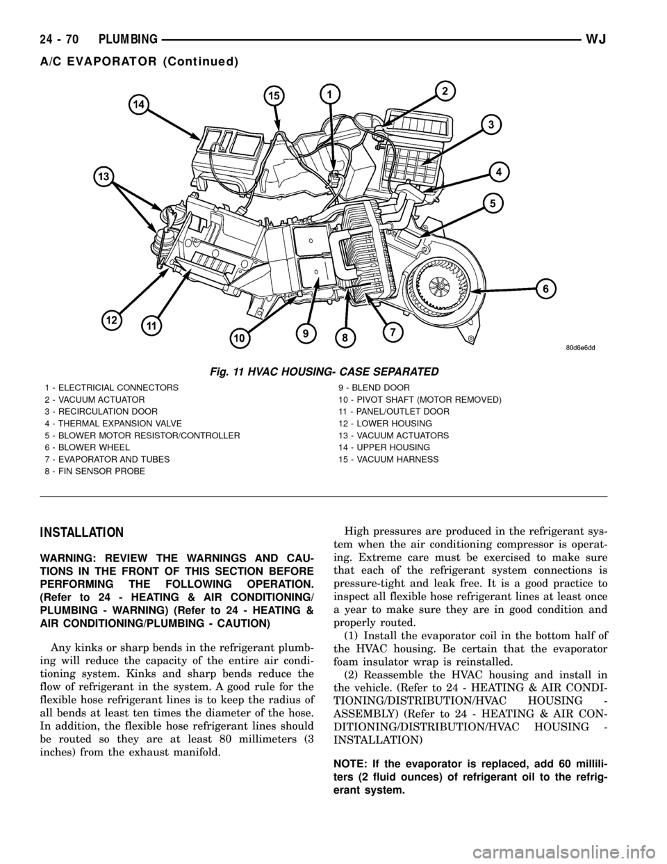
(1) Install the evaporator coil in the bottom half of
the HVAC housing. Be certain that the evaporator
foam insulator wrap is reinstalled.
(2) Reassemble the HVAC housing and install in
the vehicle. (Refer to 24 - HEATING & AIR CONDI-
TIONING/DISTRIBUTION/HVAC HOUSING -
ASSEMBLY) (Refer to 24 - HEATING & AIR CON-
DITIONING/DISTRIBUTION/HVAC HOUSING -
INSTALLATION)
NOTE: If the evaporator is replaced, add 60 millili-
ters (2 fluid ounces) of refrigerant oil to the refrig-
erant system.
Fig. 11 HVAC HOUSING- CASE SEPARATED
1 - ELECTRICIAL CONNECTORS
2 - VACUUM ACTUATOR
3 - RECIRCULATION DOOR
4 - THERMAL EXPANSION VALVE
5 - BLOWER MOTOR RESISTOR/CONTROLLER
6 - BLOWER WHEEL
7 - EVAPORATOR AND TUBES
8 - FIN SENSOR PROBE9 - BLEND DOOR
10 - PIVOT SHAFT (MOTOR REMOVED)
11 - PANEL/OUTLET DOOR
12 - LOWER HOUSING
13 - VACUUM ACTUATORS
14 - UPPER HOUSING
15 - VACUUM HARNESS
24 - 70 PLUMBINGWJ
A/C EVAPORATOR (Continued)
Page 2175 of 2199
an associated limp in will take two trips to illumi-
nate the MIL.
Refer to the Diagnostic Trouble Codes Description
Charts in this section and the appropriate Power-
train Diagnostic Procedure Manual for diagnostic
procedures.
DESCRIPTION - NON-MONITORED CIRCUITS
The PCM does not monitor the following circuits,
systems and conditions that could have malfunctions
causing driveability problems. The PCM might not
store diagnostic trouble codes for these conditions.
However, problems with these systems may cause the
PCM to store diagnostic trouble codes for other sys-
tems or components. For example, a fuel pressure
problem will not register a fault directly, but could
cause a rich/lean condition or misfire. This could
cause the PCM to store an oxygen sensor or misfire
diagnostic trouble code
FUEL PRESSURE
The fuel pressure regulator controls fuel system
pressure. The PCM cannot detect a clogged fuel
pump inlet filter, clogged in-line fuel filter, or a
pinched fuel supply or return line. However, these
could result in a rich or lean condition causing the
PCM to store an oxygen sensor or fuel system diag-
nostic trouble code.
SECONDARY IGNITION CIRCUIT
The PCM cannot detect an inoperative ignition coil,
fouled or worn spark plugs, ignition cross firing, or
open spark plug cables.
CYLINDER COMPRESSION
The PCM cannot detect uneven, low, or high engine
cylinder compression.
EXHAUST SYSTEM
The PCM cannot detect a plugged, restricted or
leaking exhaust system, although it may set a fuel
system fault.
FUEL INJECTOR MECHANICAL MALFUNCTIONS
The PCM cannot determine if a fuel injector is
clogged, the needle is sticking or if the wrong injectoris installed. However, these could result in a rich or
lean condition causing the PCM to store a diagnostic
trouble code for either misfire, an oxygen sensor, or
the fuel system.
EXCESSIVE OIL CONSUMPTION
Although the PCM monitors engine exhaust oxygen
content when the system is in closed loop, it cannot
determine excessive oil consumption.
THROTTLE BODY AIRFLOW
The PCM cannot detect a clogged or restricted air
cleaner inlet or filter element.
VACUUM ASSIST
The PCM cannot detect leaks or restrictions in the
vacuum circuits of vacuum assisted engine control
system devices. However, these could cause the PCM
to store a MAP sensor diagnostic trouble code and
cause a high idle condition.
PCM SYSTEM GROUND
The PCM cannot determine a poor system ground.
However, one or more diagnostic trouble codes may
be generated as a result of this condition. The mod-
ule should be mounted to the body at all times, also
during diagnostic.
PCM CONNECTOR ENGAGEMENT
The PCM may not be able to determine spread or
damaged connector pins. However, it might store
diagnostic trouble codes as a result of spread connec-
tor pins.
DESCRIPTION - HIGH AND LOW LIMITS
The PCM compares input signal voltages from each
input device with established high and low limits for
the device. If the input voltage is not within limits
and other criteria are met, the PCM stores a diagnos-
tic trouble code in memory. Other diagnostic trouble
code criteria might include engine RPM limits or
input voltages from other sensors or switches that
must be present before verifying a diagnostic trouble
code condition.
DESCRIPTION - LOAD VALUE
ENGINE IDLE/NEUTRAL 2500 RPM/NEUTRAL
All Engines 2% to 8% of Maximum Load 9% to 17% of Maximum Load
25 - 20 EMISSIONS CONTROLWJ
EMISSIONS CONTROL (Continued)
Page 2179 of 2199
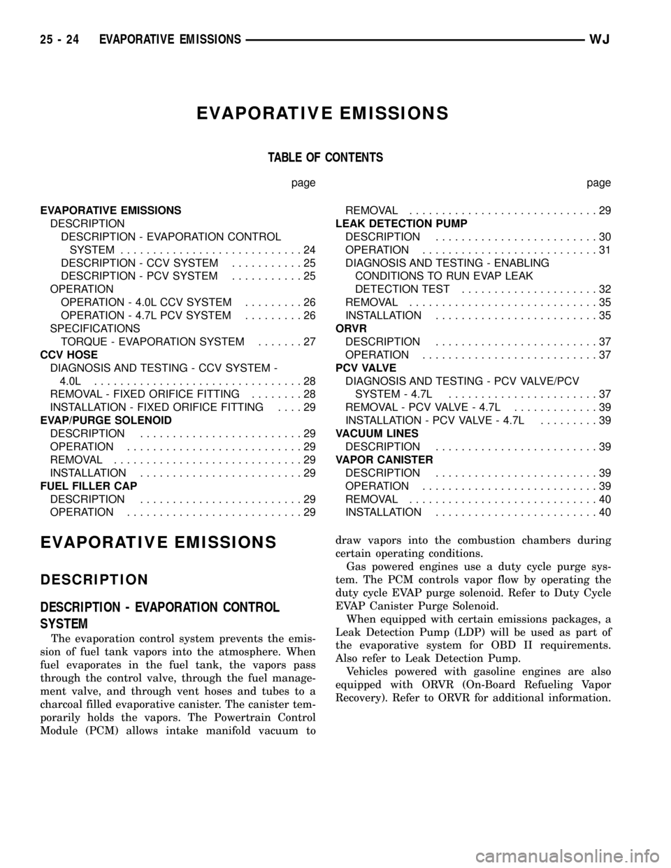
EVAPORATIVE EMISSIONS
TABLE OF CONTENTS
page page
EVAPORATIVE EMISSIONS
DESCRIPTION
DESCRIPTION - EVAPORATION CONTROL
SYSTEM............................24
DESCRIPTION - CCV SYSTEM...........25
DESCRIPTION - PCV SYSTEM...........25
OPERATION
OPERATION - 4.0L CCV SYSTEM.........26
OPERATION - 4.7L PCV SYSTEM.........26
SPECIFICATIONS
TORQUE - EVAPORATION SYSTEM.......27
CCV HOSE
DIAGNOSIS AND TESTING - CCV SYSTEM -
4.0L................................28
REMOVAL - FIXED ORIFICE FITTING........28
INSTALLATION - FIXED ORIFICE FITTING....29
EVAP/PURGE SOLENOID
DESCRIPTION.........................29
OPERATION...........................29
REMOVAL.............................29
INSTALLATION.........................29
FUEL FILLER CAP
DESCRIPTION.........................29
OPERATION...........................29REMOVAL.............................29
LEAK DETECTION PUMP
DESCRIPTION.........................30
OPERATION...........................31
DIAGNOSIS AND TESTING - ENABLING
CONDITIONS TO RUN EVAP LEAK
DETECTION TEST.....................32
REMOVAL.............................35
INSTALLATION.........................35
ORVR
DESCRIPTION.........................37
OPERATION...........................37
P C V VA LV E
DIAGNOSIS AND TESTING - PCV VALVE/PCV
SYSTEM - 4.7L.......................37
REMOVAL - PCV VALVE - 4.7L.............39
INSTALLATION - PCV VALVE - 4.7L.........39
VACUUM LINES
DESCRIPTION.........................39
VAPOR CANISTER
DESCRIPTION.........................39
OPERATION...........................39
REMOVAL.............................40
INSTALLATION.........................40
EVAPORATIVE EMISSIONS
DESCRIPTION
DESCRIPTION - EVAPORATION CONTROL
SYSTEM
The evaporation control system prevents the emis-
sion of fuel tank vapors into the atmosphere. When
fuel evaporates in the fuel tank, the vapors pass
through the control valve, through the fuel manage-
ment valve, and through vent hoses and tubes to a
charcoal filled evaporative canister. The canister tem-
porarily holds the vapors. The Powertrain Control
Module (PCM) allows intake manifold vacuum todraw vapors into the combustion chambers during
certain operating conditions.
Gas powered engines use a duty cycle purge sys-
tem. The PCM controls vapor flow by operating the
duty cycle EVAP purge solenoid. Refer to Duty Cycle
EVAP Canister Purge Solenoid.
When equipped with certain emissions packages, a
Leak Detection Pump (LDP) will be used as part of
the evaporative system for OBD II requirements.
Also refer to Leak Detection Pump.
Vehicles powered with gasoline engines are also
equipped with ORVR (On-Board Refueling Vapor
Recovery). Refer to ORVR for additional information.
25 - 24 EVAPORATIVE EMISSIONSWJ
Page 2181 of 2199
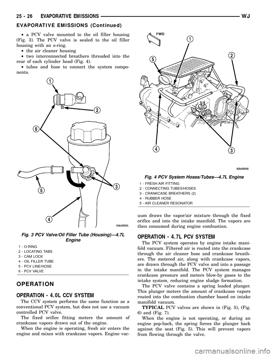
²a PCV valve mounted to the oil filler housing
(Fig. 3). The PCV valve is sealed to the oil filler
housing with an o-ring.
²the air cleaner housing
²two interconnected breathers threaded into the
rear of each cylinder head (Fig. 4).
²tubes and hose to connect the system compo-
nents.
OPERATION
OPERATION - 4.0L CCV SYSTEM
The CCV system performs the same function as a
conventional PCV system, but does not use a vacuum
controlled PCV valve.
The fixed orifice fitting meters the amount of
crankcase vapors drawn out of the engine.
When the engine is operating, fresh air enters the
engine and mixes with crankcase vapors. Engine vac-uum draws the vapor/air mixture through the fixed
orifice and into the intake manifold. The vapors are
then consumed during engine combustion.
OPERATION - 4.7L PCV SYSTEM
The PCV system operates by engine intake mani-
fold vacuum. Filtered air is routed into the crankcase
through the air cleaner hose and crankcase breath-
ers. The metered air, along with crankcase vapors,
are drawn through the PCV valve and into a passage
in the intake manifold. The PCV system manages
crankcase pressure and meters blow-by gases to the
intake system, reducing engine sludge formation.
The PCV valve contains a spring loaded plunger.
This plunger meters the amount of crankcase vapors
routed into the combustion chamber based on intake
manifold vacuum.
TYPICALPCV valves are shown in (Fig. 5), (Fig.
6) and (Fig. 7).
When the engine is not operating, or during an
engine pop-back, the spring forces the plunger back
against the seat (Fig. 5). This will prevent vapors
from flowing through the valve.
Fig. 3 PCV Valve/Oil Filler Tube (Housing)Ð4.7L
Engine
1 - O-RING
2 - LOCATING TABS
3 - CAM LOCK
4 - OIL FILLER TUBE
5 - PCV LINE/HOSE
6 - P C V VA LV E
Fig. 4 PCV System Hoses/TubesÐ4.7L Engine
1 - FRESH AIR FITTING
2 - CONNECTING TUBES/HOSES
3 - CRANKCASE BREATHERS (2)
4 - RUBBER HOSE
5 - AIR CLEANER RESONATOR
25 - 26 EVAPORATIVE EMISSIONSWJ
EVAPORATIVE EMISSIONS (Continued)
Page 2183 of 2199
CCV HOSE
DIAGNOSIS AND TESTING - CCV SYSTEM -
4.0L
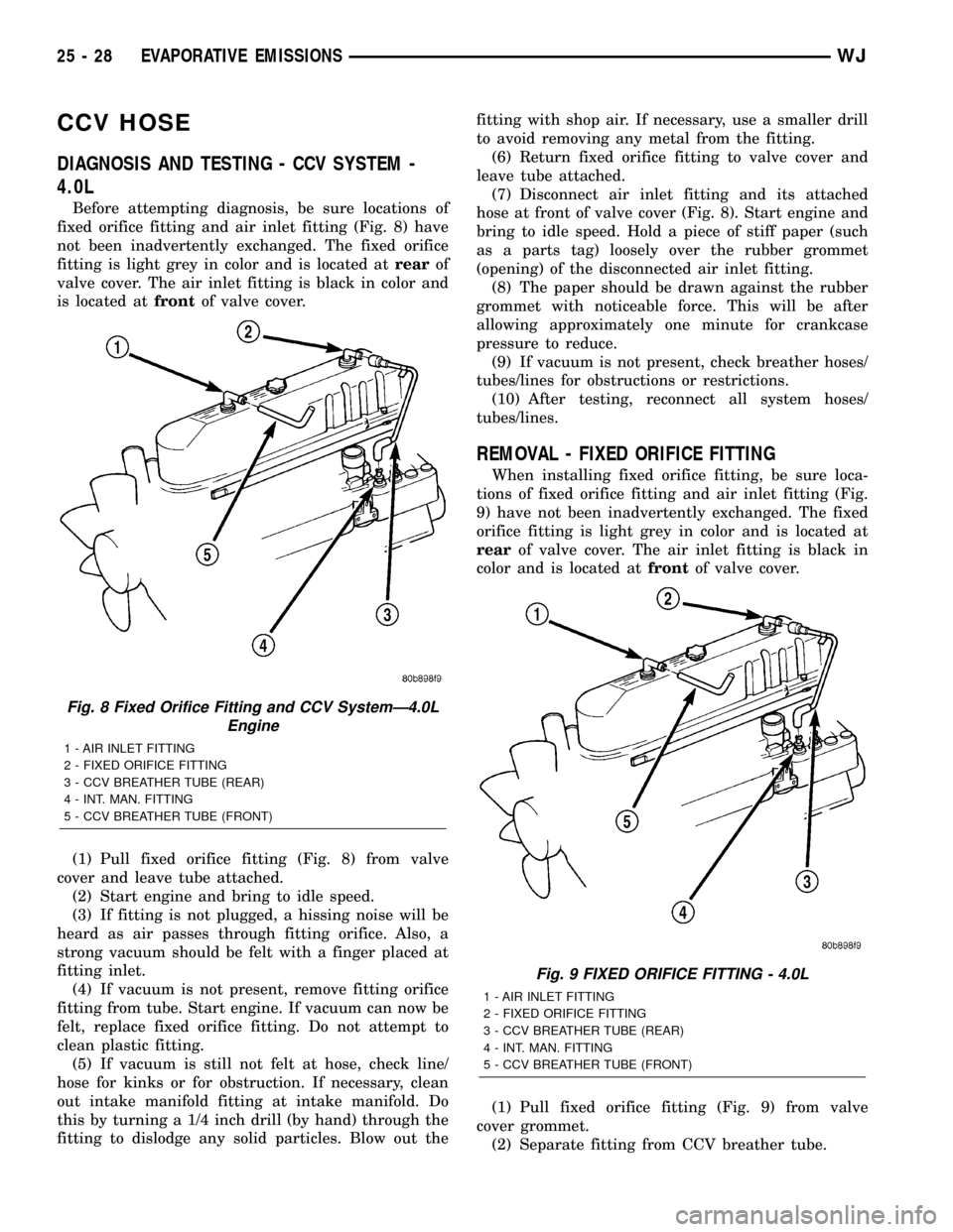
Before attempting diagnosis, be sure locations of
fixed orifice fitting and air inlet fitting (Fig. 8) have
not been inadvertently exchanged. The fixed orifice
fitting is light grey in color and is located atrearof
valve cover. The air inlet fitting is black in color and
is located atfrontof valve cover.
(1) Pull fixed orifice fitting (Fig. 8) from valve
cover and leave tube attached.
(2) Start engine and bring to idle speed.
(3) If fitting is not plugged, a hissing noise will be
heard as air passes through fitting orifice. Also, a
strong vacuum should be felt with a finger placed at
fitting inlet.
(4) If vacuum is not present, remove fitting orifice
fitting from tube. Start engine. If vacuum can now be
felt, replace fixed orifice fitting. Do not attempt to
clean plastic fitting.
(5) If vacuum is still not felt at hose, check line/
hose for kinks or for obstruction. If necessary, clean
out intake manifold fitting at intake manifold. Do
this by turning a 1/4 inch drill (by hand) through the
fitting to dislodge any solid particles. Blow out thefitting with shop air. If necessary, use a smaller drill
to avoid removing any metal from the fitting.
(6) Return fixed orifice fitting to valve cover and
leave tube attached.
(7) Disconnect air inlet fitting and its attached
hose at front of valve cover (Fig. 8). Start engine and
bring to idle speed. Hold a piece of stiff paper (such
as a parts tag) loosely over the rubber grommet
(opening) of the disconnected air inlet fitting.
(8) The paper should be drawn against the rubber
grommet with noticeable force. This will be after
allowing approximately one minute for crankcase
pressure to reduce.
(9) If vacuum is not present, check breather hoses/
tubes/lines for obstructions or restrictions.
(10) After testing, reconnect all system hoses/
tubes/lines.
REMOVAL - FIXED ORIFICE FITTING
When installing fixed orifice fitting, be sure loca-
tions of fixed orifice fitting and air inlet fitting (Fig.
9) have not been inadvertently exchanged. The fixed
orifice fitting is light grey in color and is located at
rearof valve cover. The air inlet fitting is black in
color and is located atfrontof valve cover.
(1) Pull fixed orifice fitting (Fig. 9) from valve
cover grommet.
(2) Separate fitting from CCV breather tube.
Fig. 8 Fixed Orifice Fitting and CCV SystemÐ4.0L
Engine
1 - AIR INLET FITTING
2 - FIXED ORIFICE FITTING
3 - CCV BREATHER TUBE (REAR)
4 - INT. MAN. FITTING
5 - CCV BREATHER TUBE (FRONT)
Fig. 9 FIXED ORIFICE FITTING - 4.0L
1 - AIR INLET FITTING
2 - FIXED ORIFICE FITTING
3 - CCV BREATHER TUBE (REAR)
4 - INT. MAN. FITTING
5 - CCV BREATHER TUBE (FRONT)
25 - 28 EVAPORATIVE EMISSIONSWJ
Page 2184 of 2199
INSTALLATION - FIXED ORIFICE FITTING
When installing fixed orifice fitting, be sure loca-
tions of fixed orifice fitting and air inlet fitting (Fig.
9) have not been inadvertently exchanged. The fixed
orifice fitting is light grey in color and is located at
rearof valve cover. The air inlet fitting is black in
color and is located atfrontof valve cover.
(1) Connect fitting to CCV breather tube.
(2) Return fixed orifice fitting to valve cover grom-
met.
EVAP/PURGE SOLENOID
DESCRIPTION
The duty cycle EVAP canister purge solenoid (DCP)
regulates the rate of vapor flow from the EVAP can-
ister to the intake manifold. The Powertrain Control
Module (PCM) operates the solenoid.
OPERATION
During the cold start warm-up period and the hot
start time delay, the PCM does not energize the sole-
noid. When de-energized, no vapors are purged. The
PCM de-energizes the solenoid during open loop oper-
ation.
The engine enters closed loop operation after it
reaches a specified temperature and the time delay
ends. During closed loop operation, the PCM cycles
(energizes and de-energizes) the solenoid 5 or 10
times per second, depending upon operating condi-
tions. The PCM varies the vapor flow rate by chang-
ing solenoid pulse width. Pulse width is the amount
of time that the solenoid is energized. The PCM
adjusts solenoid pulse width based on engine operat-
ing condition.
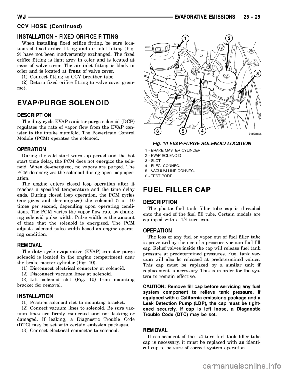
REMOVAL
The duty cycle evaporative (EVAP) canister purge
solenoid is located in the engine compartment near
the brake master cylinder (Fig. 10).
(1) Disconnect electrical connector at solenoid.
(2) Disconnect vacuum lines at solenoid.
(3) Lift solenoid slot (Fig. 10) from mounting
bracket for removal.
INSTALLATION
(1) Position solenoid slot to mounting bracket.
(2) Connect vacuum lines to solenoid. Be sure vac-
uum lines are firmly connected and not leaking or
damaged. If leaking, a Diagnostic Trouble Code
(DTC) may be set with certain emission packages.
(3) Connect electrical connector to solenoid.
FUEL FILLER CAP
DESCRIPTION
The plastic fuel tank filler tube cap is threaded
onto the end of the fuel fill tube. Certain models are
equipped with a 1/4 turn cap.
OPERATION
The loss of any fuel or vapor out of fuel filler tube
is prevented by the use of a pressure-vacuum fuel fill
cap. Relief valves inside the cap will release fuel tank
pressure at predetermined pressures. Fuel tank vac-
uum will also be released at predetermined values.
This cap must be replaced by a similar unit if
replacement is necessary. This is in order for the sys-
tem to remain effective.
CAUTION: Remove fill cap before servicing any fuel
system component to relieve tank pressure. If
equipped with a California emissions package and a
Leak Detection Pump (LDP), the cap must be tight-
ened securely. If cap is left loose, a Diagnostic
Trouble Code (DTC) may be set.
REMOVAL
If replacement of the 1/4 turn fuel tank filler tube
cap is necessary, it must be replaced with an identi-
cal cap to be sure of correct system operation.
Fig. 10 EVAP/PURGE SOLENOID LOCATION
1 - BRAKE MASTER CYLINDER
2 - EVAP SOLENOID
3 - SLOT
4 - ELEC. CONNEC.
5 - VACUUM LINE CONNEC.
6 - TEST PORT
WJEVAPORATIVE EMISSIONS 25 - 29
CCV HOSE (Continued)