2003 JEEP GRAND CHEROKEE Exhaust intake
[x] Cancel search: Exhaust intakePage 1343 of 2199
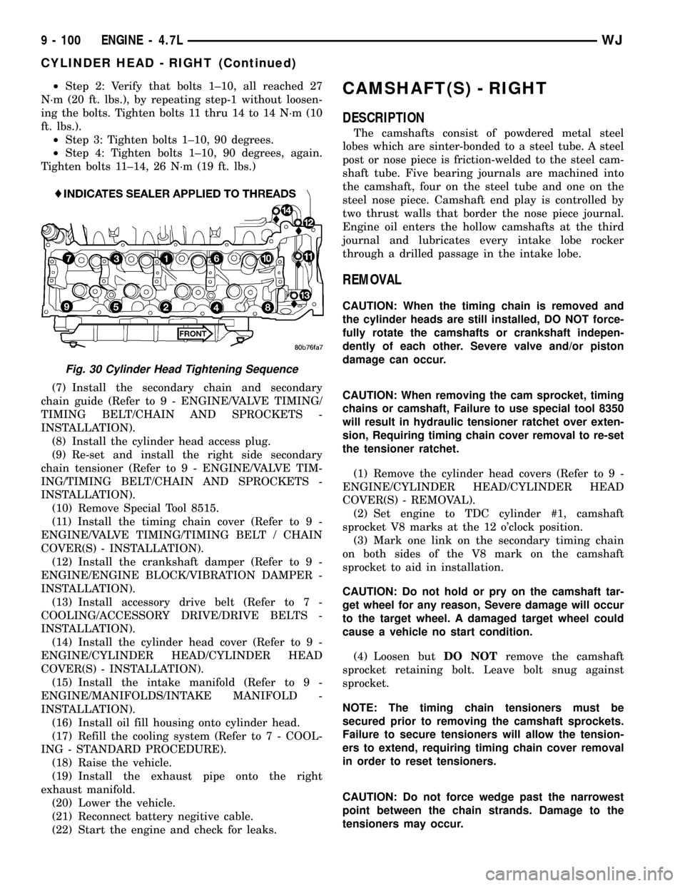
²Step 2: Verify that bolts 1±10, all reached 27
N´m (20 ft. lbs.), by repeating step-1 without loosen-
ing the bolts. Tighten bolts 11 thru 14 to 14 N´m (10
ft. lbs.).
²Step 3: Tighten bolts 1±10, 90 degrees.
²Step 4: Tighten bolts 1±10, 90 degrees, again.
Tighten bolts 11±14, 26 N´m (19 ft. lbs.)
(7) Install the secondary chain and secondary
chain guide (Refer to 9 - ENGINE/VALVE TIMING/
TIMING BELT/CHAIN AND SPROCKETS -
INSTALLATION).
(8) Install the cylinder head access plug.
(9) Re-set and install the right side secondary
chain tensioner (Refer to 9 - ENGINE/VALVE TIM-
ING/TIMING BELT/CHAIN AND SPROCKETS -
INSTALLATION).
(10) Remove Special Tool 8515.
(11) Install the timing chain cover (Refer to 9 -
ENGINE/VALVE TIMING/TIMING BELT / CHAIN
COVER(S) - INSTALLATION).
(12) Install the crankshaft damper (Refer to 9 -
ENGINE/ENGINE BLOCK/VIBRATION DAMPER -
INSTALLATION).
(13) Install accessory drive belt (Refer to 7 -
COOLING/ACCESSORY DRIVE/DRIVE BELTS -
INSTALLATION).
(14) Install the cylinder head cover (Refer to 9 -
ENGINE/CYLINDER HEAD/CYLINDER HEAD
COVER(S) - INSTALLATION).
(15) Install the intake manifold (Refer to 9 -
ENGINE/MANIFOLDS/INTAKE MANIFOLD -
INSTALLATION).
(16) Install oil fill housing onto cylinder head.
(17) Refill the cooling system (Refer to 7 - COOL-
ING - STANDARD PROCEDURE).
(18) Raise the vehicle.
(19) Install the exhaust pipe onto the right
exhaust manifold.
(20) Lower the vehicle.
(21) Reconnect battery negitive cable.
(22) Start the engine and check for leaks.CAMSHAFT(S) - RIGHT
DESCRIPTION
The camshafts consist of powdered metal steel
lobes which are sinter-bonded to a steel tube. A steel
post or nose piece is friction-welded to the steel cam-
shaft tube. Five bearing journals are machined into
the camshaft, four on the steel tube and one on the
steel nose piece. Camshaft end play is controlled by
two thrust walls that border the nose piece journal.
Engine oil enters the hollow camshafts at the third
journal and lubricates every intake lobe rocker
through a drilled passage in the intake lobe.
REMOVAL
CAUTION: When the timing chain is removed and
the cylinder heads are still installed, DO NOT force-
fully rotate the camshafts or crankshaft indepen-
dently of each other. Severe valve and/or piston
damage can occur.
CAUTION: When removing the cam sprocket, timing
chains or camshaft, Failure to use special tool 8350
will result in hydraulic tensioner ratchet over exten-
sion, Requiring timing chain cover removal to re-set
the tensioner ratchet.
(1) Remove the cylinder head covers (Refer to 9 -
ENGINE/CYLINDER HEAD/CYLINDER HEAD
COVER(S) - REMOVAL).
(2) Set engine to TDC cylinder #1, camshaft
sprocket V8 marks at the 12 o'clock position.
(3) Mark one link on the secondary timing chain
on both sides of the V8 mark on the camshaft
sprocket to aid in installation.
CAUTION: Do not hold or pry on the camshaft tar-
get wheel for any reason, Severe damage will occur
to the target wheel. A damaged target wheel could
cause a vehicle no start condition.
(4) Loosen butDO NOTremove the camshaft
sprocket retaining bolt. Leave bolt snug against
sprocket.
NOTE: The timing chain tensioners must be
secured prior to removing the camshaft sprockets.
Failure to secure tensioners will allow the tension-
ers to extend, requiring timing chain cover removal
in order to reset tensioners.
CAUTION: Do not force wedge past the narrowest
point between the chain strands. Damage to the
tensioners may occur.
Fig. 30 Cylinder Head Tightening Sequence
9 - 100 ENGINE - 4.7LWJ
CYLINDER HEAD - RIGHT (Continued)
Page 1347 of 2199
CYLINDER HEAD COVER(S) -
RIGHT
DESCRIPTION
The cylinder head covers are made of die cast mag-
nesium, and are not interchangeable from side-to-
side. It is imperative that nothing rest on the
cylinder head covers. Prolonged contact with other
items may wear a hole in the cylinder head cover.
REMOVAL - RIGHT SIDE
(1) Disconnect battery negative cable.
(2) Remove air cleaner assembly, resonator assem-
bly and air inlet hose.
(3) Drain cooling system (Refer to 7 - COOLING -
STANDARD PROCEDURE).
(4) Remove accessory drive belt (Refer to 7 -
COOLING/ACCESSORY DRIVE/DRIVE BELTS -
REMOVAL).
(5) Remove air conditioning compressor retaining
bolts and move compressor to the left.
(6) Remove heater hoses.
(7) Disconnect injector and ignition coil connectors.
(8) Disconnect and remove positive crankcase ven-
tilation (PCV) hose.
(9) Remove oil fill tube.
(10) Un-clip injector and ignition coil harness and
move away from cylinder head cover.
(11) Remove right rear breather tube and filter
assembly.
(12) Remove cylinder head cover retaining bolts.
(13) Remove cylinder head cover.
NOTE: The gasket may be used again, provided no
cuts, tears, or deformation has occurred.
CLEANING
Clean cylinder head cover gasket surface.
Clean head rail, if necessary.
INSTALLATION - RIGHT SIDE
CAUTION: Do not use harsh cleaners to clean the
cylinder head covers. Severe damage to covers
may occur.
CAUTION: DO NOT allow other components includ-
ing the wire harness to rest on or against the
engine cylinder head cover. Prolonged contact with
other objects may wear a hole in the cylinder head
cover.
(1) Clean cylinder head cover and both sealing sur-
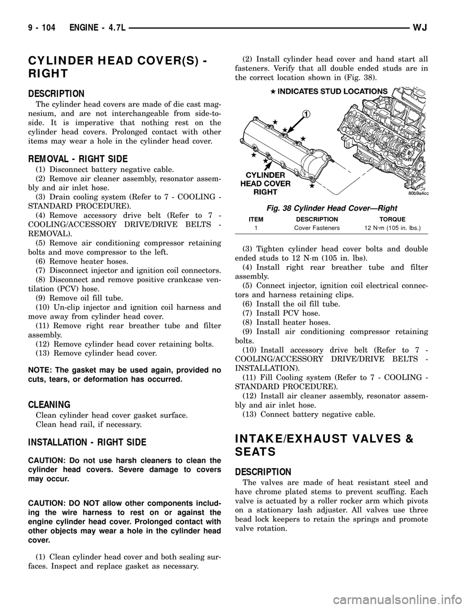
faces. Inspect and replace gasket as necessary.(2) Install cylinder head cover and hand start all
fasteners. Verify that all double ended studs are in
the correct location shown in (Fig. 38).
(3) Tighten cylinder head cover bolts and double
ended studs to 12 N´m (105 in. lbs).
(4) Install right rear breather tube and filter
assembly.
(5) Connect injector, ignition coil electrical connec-
tors and harness retaining clips.
(6) Install the oil fill tube.
(7) Install PCV hose.
(8) Install heater hoses.
(9) Install air conditioning compressor retaining
bolts.
(10) Install accessory drive belt (Refer to 7 -
COOLING/ACCESSORY DRIVE/DRIVE BELTS -
INSTALLATION).
(11) Fill Cooling system (Refer to 7 - COOLING -
STANDARD PROCEDURE).
(12) Install air cleaner assembly, resonator assem-
bly and air inlet hose.
(13) Connect battery negative cable.
INTAKE/EXHAUST VALVES &
SEATS
DESCRIPTION
The valves are made of heat resistant steel and
have chrome plated stems to prevent scuffing. Each
valve is actuated by a roller rocker arm which pivots
on a stationary lash adjuster. All valves use three
bead lock keepers to retain the springs and promote
valve rotation.
Fig. 38 Cylinder Head CoverÐRight
ITEM DESCRIPTION TORQUE
1 Cover Fasteners 12 N´m (105 in. lbs.)
9 - 104 ENGINE - 4.7LWJ
Page 1348 of 2199
STANDARD PROCEDUREÐREFACING
NOTE: Valve seats that are worn or burned can be
reworked, provided that correct angle and seat
width are maintained. Otherwise the cylinder head
must be replaced.
NOTE: When refacing valves and valve seats, it is
important that the correct size valve guide pilot be
used for reseating stones. A true and complete sur-
face must be obtained.
(1) Using a suitable dial indicator measure the
center of the valve seat Total run out must not
exceed 0.051 mm (0.002 in).
(2) Apply a small amount of Prussian blue to the
valve seat, insert the valve into the cylinder head,
while applying light pressure on the valve rotate the
valve. Remove the valve and examine the valve face.
If the blue is transferred below the top edge of the
valve face, lower the valve seat using a 15 degree
stone. If the blue is transferred to the bottom edge of
the valve face, raise the valve seat using a 65 degree
stone.
(3) When the seat is properly positioned the width
of the intake seat must be 1.75 ± 2.36 mm (0.0689 ±
0.0928 in.) and the exhaust seat must be 1.71 ± 2.32
mm (0.0673 ± 0.0911 in.).
(4) Check the valve spring installed height after
refacing the valve and seat. The installed height for
both intake and exhaust valve springs must not
exceed 41.44 mm (1.6315 in.).
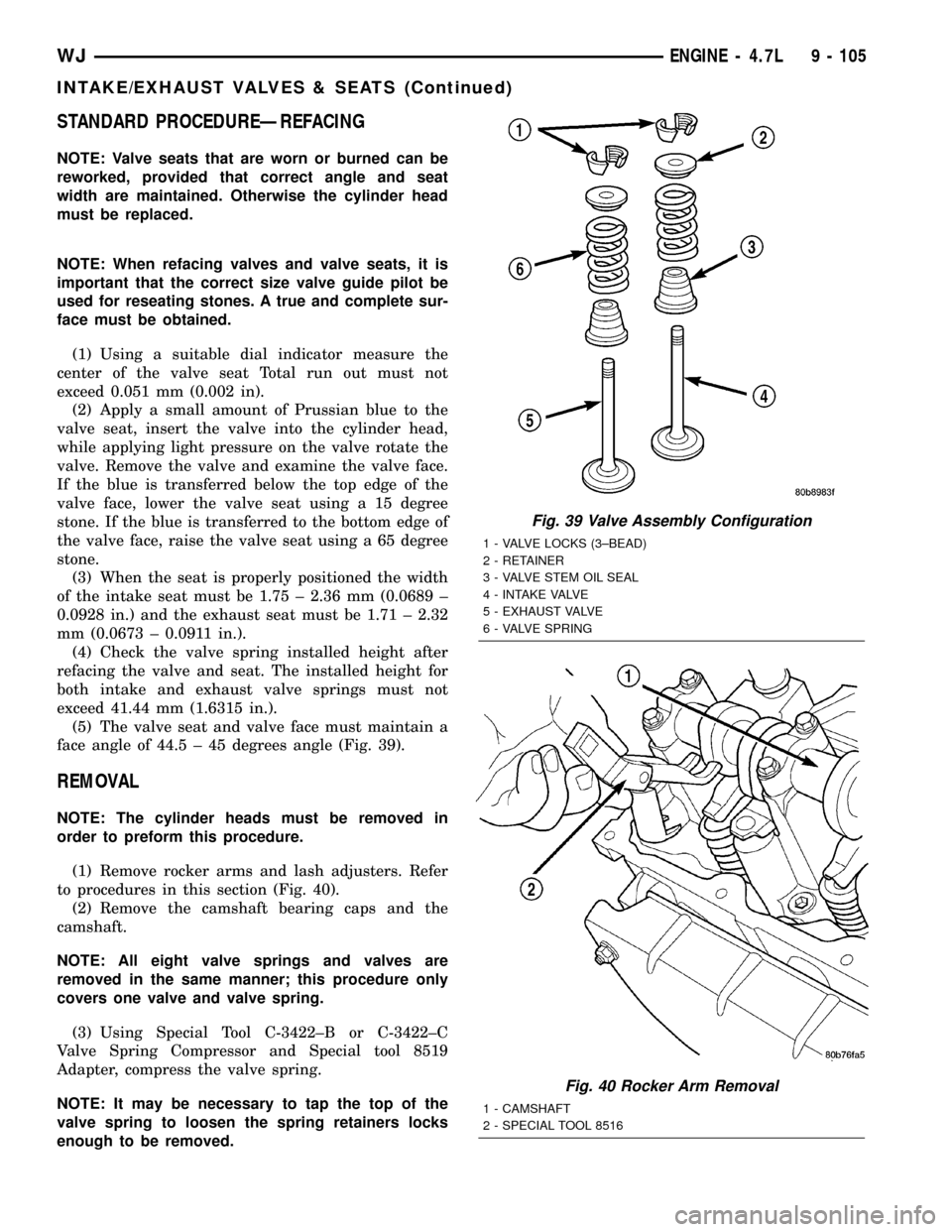
(5) The valve seat and valve face must maintain a
face angle of 44.5 ± 45 degrees angle (Fig. 39).
REMOVAL
NOTE: The cylinder heads must be removed in
order to preform this procedure.
(1) Remove rocker arms and lash adjusters. Refer
to procedures in this section (Fig. 40).
(2) Remove the camshaft bearing caps and the
camshaft.
NOTE: All eight valve springs and valves are
removed in the same manner; this procedure only
covers one valve and valve spring.
(3) Using Special Tool C-3422±B or C-3422±C
Valve Spring Compressor and Special tool 8519
Adapter, compress the valve spring.
NOTE: It may be necessary to tap the top of the
valve spring to loosen the spring retainers locks
enough to be removed.
Fig. 39 Valve Assembly Configuration
1 - VALVE LOCKS (3±BEAD)
2 - RETAINER
3 - VALVE STEM OIL SEAL
4 - INTAKE VALVE
5 - EXHAUST VALVE
6 - VALVE SPRING
Fig. 40 Rocker Arm Removal
1 - CAMSHAFT
2 - SPECIAL TOOL 8516
WJENGINE - 4.7L 9 - 105
INTAKE/EXHAUST VALVES & SEATS (Continued)
Page 1349 of 2199
(4) Remove the two spring retainer lock halves.
NOTE: the valve spring is under tension use care
when releasing the valve spring compressor.
(5) Remove the valve spring compressor.
(6) Remove the spring retainer, and the spring.
NOTE: Check for sharp edges on the keeper
grooves. Remove any burrs from the valve stem
before removing the valve from the cylinder head.
(7) Remove the valve from the cylinder head.
NOTE: The valve stem seals are common between
intake and exhaust.
(8) Remove the valve stem seal. Mark the valve for
proper installation.
TESTING VALVE SPRINGS
NOTE: Whenever the valves are removed from the
cylinder head it is recommended that the valve
springs be inspected and tested for reuse.
Inspect the valve springs for physical signs of wear
or damage. Turn table of tool C-647 until surface is
in line with the 40.69 mm (1.602 in.) mark on the
threaded stud and the zero mark on the front. Place
spring over the stud on the table and lift compress-
ing lever to set tone device. Pull on torque wrench
until Ping is heard. Take reading on torque wrench
at this instant. Multiply this reading by two. This
will give the spring load at test length. Fractional
measurements are indicated on the table for finer
adjustments. Refer to Specifications Section to obtain
specified height and allowable tensions. Replace any
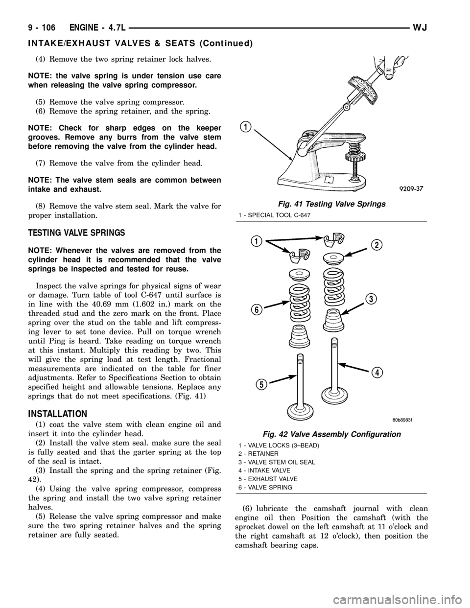
springs that do not meet specifications. (Fig. 41)
INSTALLATION
(1) coat the valve stem with clean engine oil and
insert it into the cylinder head.
(2) Install the valve stem seal. make sure the seal
is fully seated and that the garter spring at the top
of the seal is intact.
(3) Install the spring and the spring retainer (Fig.
42).
(4) Using the valve spring compressor, compress
the spring and install the two valve spring retainer
halves.
(5) Release the valve spring compressor and make
sure the two spring retainer halves and the spring
retainer are fully seated.(6) lubricate the camshaft journal with clean
engine oil then Position the camshaft (with the
sprocket dowel on the left camshaft at 11 o'clock and
the right camshaft at 12 o'clock), then position the
camshaft bearing caps.
Fig. 41 Testing Valve Springs
1 - SPECIAL TOOL C-647
Fig. 42 Valve Assembly Configuration
1 - VALVE LOCKS (3±BEAD)
2 - RETAINER
3 - VALVE STEM OIL SEAL
4 - INTAKE VALVE
5 - EXHAUST VALVE
6 - VALVE SPRING
9 - 106 ENGINE - 4.7LWJ
INTAKE/EXHAUST VALVES & SEATS (Continued)
Page 1350 of 2199
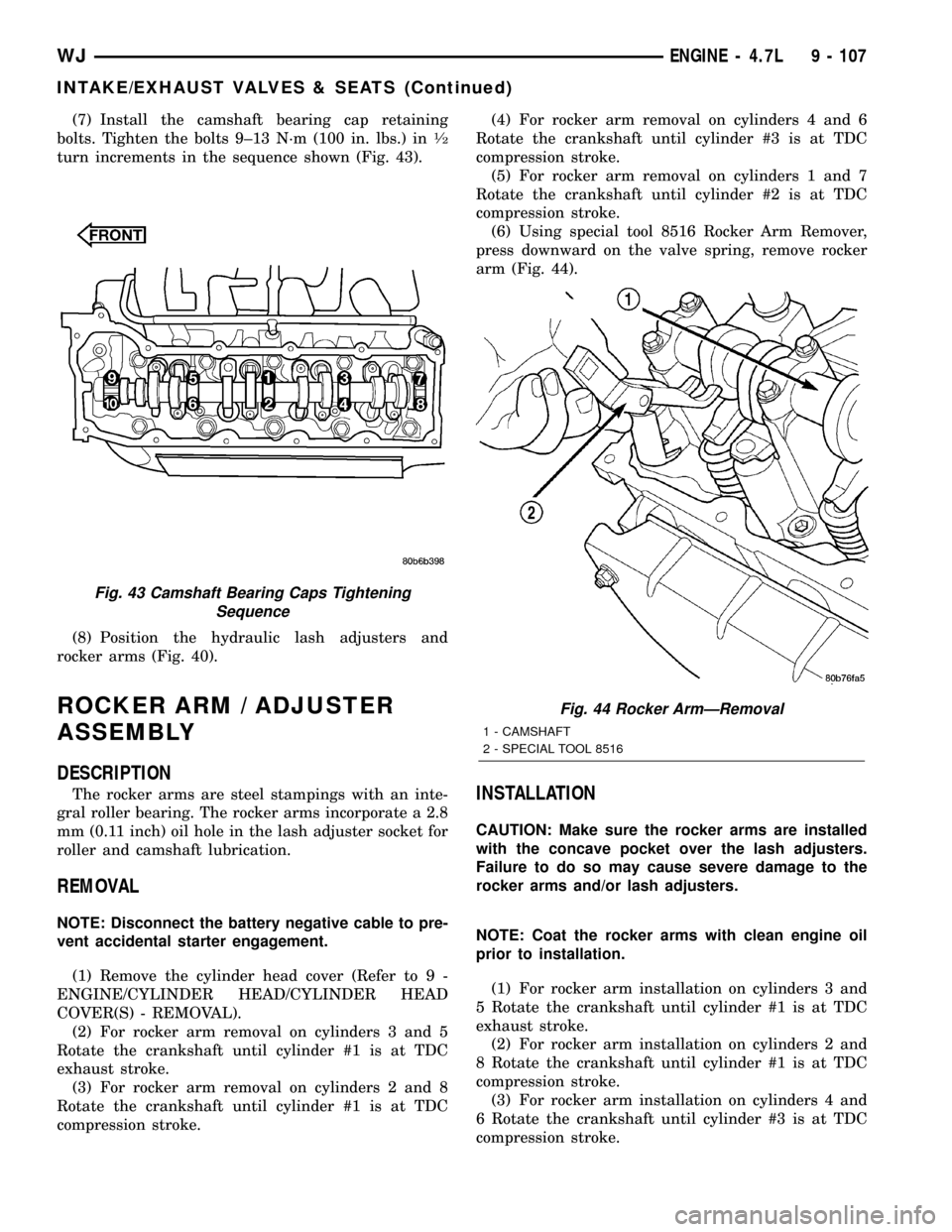
(7) Install the camshaft bearing cap retaining
bolts. Tighten the bolts 9±13 N´m (100 in. lbs.) in1¤2
turn increments in the sequence shown (Fig. 43).
(8) Position the hydraulic lash adjusters and
rocker arms (Fig. 40).
ROCKER ARM / ADJUSTER
ASSEMBLY
DESCRIPTION
The rocker arms are steel stampings with an inte-
gral roller bearing. The rocker arms incorporate a 2.8
mm (0.11 inch) oil hole in the lash adjuster socket for
roller and camshaft lubrication.
REMOVAL
NOTE: Disconnect the battery negative cable to pre-
vent accidental starter engagement.
(1) Remove the cylinder head cover (Refer to 9 -
ENGINE/CYLINDER HEAD/CYLINDER HEAD
COVER(S) - REMOVAL).
(2) For rocker arm removal on cylinders 3 and 5
Rotate the crankshaft until cylinder #1 is at TDC
exhaust stroke.
(3) For rocker arm removal on cylinders 2 and 8
Rotate the crankshaft until cylinder #1 is at TDC
compression stroke.(4) For rocker arm removal on cylinders 4 and 6
Rotate the crankshaft until cylinder #3 is at TDC
compression stroke.
(5) For rocker arm removal on cylinders 1 and 7
Rotate the crankshaft until cylinder #2 is at TDC
compression stroke.
(6) Using special tool 8516 Rocker Arm Remover,
press downward on the valve spring, remove rocker
arm (Fig. 44).
INSTALLATION
CAUTION: Make sure the rocker arms are installed
with the concave pocket over the lash adjusters.
Failure to do so may cause severe damage to the
rocker arms and/or lash adjusters.
NOTE: Coat the rocker arms with clean engine oil
prior to installation.
(1) For rocker arm installation on cylinders 3 and
5 Rotate the crankshaft until cylinder #1 is at TDC
exhaust stroke.
(2) For rocker arm installation on cylinders 2 and
8 Rotate the crankshaft until cylinder #1 is at TDC
compression stroke.
(3) For rocker arm installation on cylinders 4 and
6 Rotate the crankshaft until cylinder #3 is at TDC
compression stroke.
Fig. 43 Camshaft Bearing Caps Tightening
Sequence
Fig. 44 Rocker ArmÐRemoval
1 - CAMSHAFT
2 - SPECIAL TOOL 8516
WJENGINE - 4.7L 9 - 107
INTAKE/EXHAUST VALVES & SEATS (Continued)
Page 1351 of 2199
(4) For rocker arm installation on cylinders 1 and
7 Rotate the crankshaft until cylinder #2 is at TDC
compression stroke.
(5) Using special tool 8516 press downward on the
valve spring, install rocker arm (Fig. 44).
(6) Install the cylinder head cover (Refer to 9 -
ENGINE/CYLINDER HEAD/CYLINDER HEAD
COVER(S) - INSTALLATION).
VALVE SPRINGS
DESCRIPTION
The valve springs are made from high strength
chrome silicon steel. The springs are common for
intake and exhaust applications. The valve spring
seat is integral with the valve stem seal, which is a
positive type seal to control lubrication.
VALVE STEM SEALS
DESCRIPTION
The valve stem seals are made of rubber and incor-
porate an integral steel valve spring seat. The inte-
gral garter spring maintains consistent lubrication
control to the valve stems.
ENGINE BLOCK
DESCRIPTION
The cylinder block is made of cast iron. The block
is a closed deck design with the left bank forward. To
provide high rigidity and improved NVH an
enhanced compacted graphite bedplate is bolted to
the block. The block design allows coolant flow
between the cylinders bores, and an internal coolant
bypass to a single poppet inlet thermostat is included
in the cast aluminum front cover.
STANDARD PROCEDUREÐCYLINDER BORE
HONING
Before honing, stuff plenty of clean shop towels
under the bores and over the crankshaft to keep
abrasive materials from entering the crankshaft
area.
(1) Used carefully, the Cylinder Bore Sizing Hone
C-823, equipped with 220 grit stones, is the best tool
for this job. In addition to deglazing, it will reduce
taper and out-of-round, as well as removing light
scuffing, scoring and scratches. Usually, a few strokes
will clean up a bore and maintain the required lim-
its.CAUTION: DO NOT use rigid type hones to remove
cylinder wall glaze.
(2) Deglazing of the cylinder walls may be done if
the cylinder bore is straight and round. Use a cylin-
der surfacing hone, Honing Tool C-3501, equipped
with 280 grit stones (C-3501-3810). about 20-60
strokes, depending on the bore condition, will be suf-
ficient to provide a satisfactory surface. Using honing
oil C-3501-3880, or a light honing oil, available from
major oil distributors.
CAUTION: DO NOT use engine or transmission oil,
mineral spirits, or kerosene.
(3) Honing should be done by moving the hone up
and down fast enough to get a crosshatch pattern.
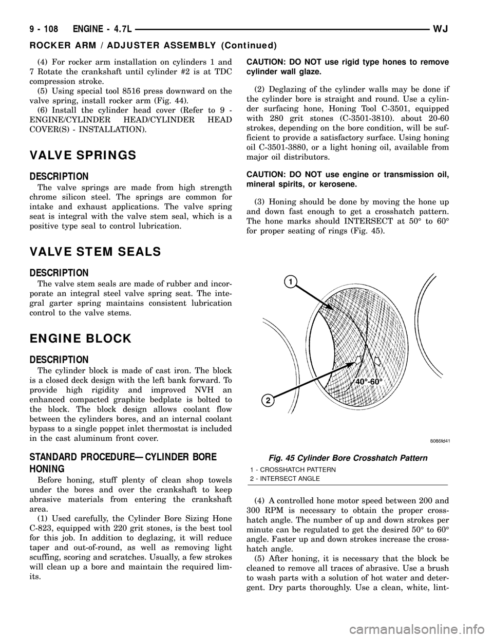
The hone marks should INTERSECT at 50É to 60É
for proper seating of rings (Fig. 45).
(4) A controlled hone motor speed between 200 and
300 RPM is necessary to obtain the proper cross-
hatch angle. The number of up and down strokes per
minute can be regulated to get the desired 50É to 60É
angle. Faster up and down strokes increase the cross-
hatch angle.
(5) After honing, it is necessary that the block be
cleaned to remove all traces of abrasive. Use a brush
to wash parts with a solution of hot water and deter-
gent. Dry parts thoroughly. Use a clean, white, lint-
Fig. 45 Cylinder Bore Crosshatch Pattern
1 - CROSSHATCH PATTERN
2 - INTERSECT ANGLE
9 - 108 ENGINE - 4.7LWJ
ROCKER ARM / ADJUSTER ASSEMBLY (Continued)
Page 1369 of 2199
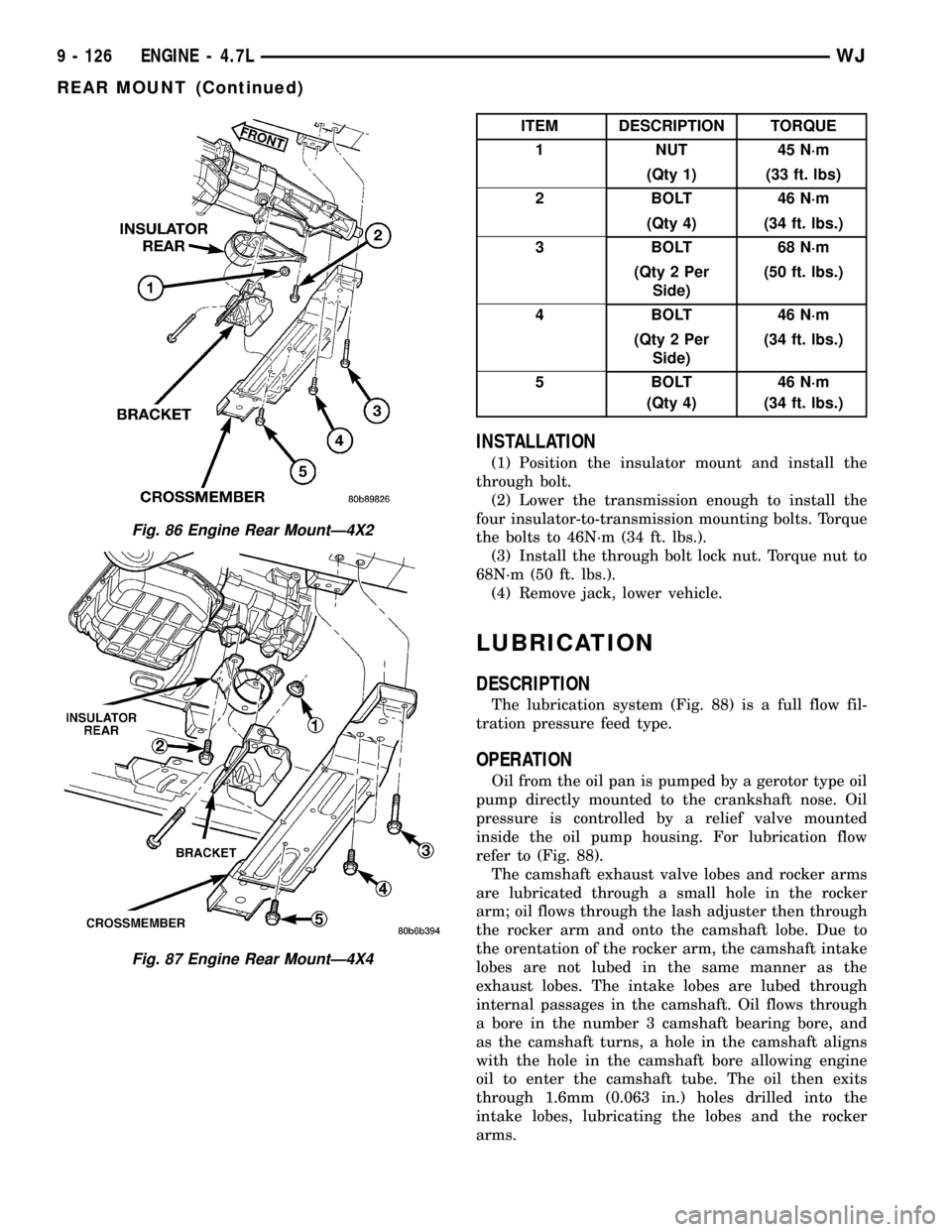
ITEM DESCRIPTION TORQUE
1 NUT 45 N´m
(Qty 1) (33 ft. lbs)
2 BOLT 46 N´m
(Qty 4) (34 ft. lbs.)
3 BOLT 68 N´m
(Qty 2 Per
Side)(50 ft. lbs.)
4 BOLT 46 N´m
(Qty 2 Per
Side)(34 ft. lbs.)
5 BOLT 46 N´m
(Qty 4) (34 ft. lbs.)
INSTALLATION
(1) Position the insulator mount and install the
through bolt.
(2) Lower the transmission enough to install the
four insulator-to-transmission mounting bolts. Torque
the bolts to 46N´m (34 ft. lbs.).
(3) Install the through bolt lock nut. Torque nut to
68N´m (50 ft. lbs.).
(4) Remove jack, lower vehicle.
LUBRICATION
DESCRIPTION
The lubrication system (Fig. 88) is a full flow fil-
tration pressure feed type.
OPERATION
Oil from the oil pan is pumped by a gerotor type oil
pump directly mounted to the crankshaft nose. Oil
pressure is controlled by a relief valve mounted
inside the oil pump housing. For lubrication flow
refer to (Fig. 88).
The camshaft exhaust valve lobes and rocker arms
are lubricated through a small hole in the rocker
arm; oil flows through the lash adjuster then through
the rocker arm and onto the camshaft lobe. Due to
the orentation of the rocker arm, the camshaft intake
lobes are not lubed in the same manner as the
exhaust lobes. The intake lobes are lubed through
internal passages in the camshaft. Oil flows through
a bore in the number 3 camshaft bearing bore, and
as the camshaft turns, a hole in the camshaft aligns
with the hole in the camshaft bore allowing engine
oil to enter the camshaft tube. The oil then exits
through 1.6mm (0.063 in.) holes drilled into the
intake lobes, lubricating the lobes and the rocker
arms.
Fig. 86 Engine Rear MountÐ4X2
Fig. 87 Engine Rear MountÐ4X4
9 - 126 ENGINE - 4.7LWJ
REAR MOUNT (Continued)
Page 1381 of 2199

(7) Connect throttle cable and speed control cable
to throttle body.
(8) Install fuel rail (Refer to 14 - FUEL SYSTEM/
FUEL DELIVERY/FUEL RAIL - INSTALLATION).
(9) Install ignition coil towers (Refer to 8 - ELEC-
TRICAL/IGNITION CONTROL/IGNITION COIL -
INSTALLATION).
(10) Install coolant temperature sensor (Refer to 7
- COOLING/ENGINE/ENGINE COOLANT TEMP
SENSOR - INSTALLATION).
(11) Connect electrical connectors for the following
components:
²Manifold Absolute Pressure (MAP) Sensor
²Intake Air Temperature (IAT) Sensor
²Throttle Position (TPS) Sensor
²Coolant Temperature (CTS) Sensor
²Idle Air Control (IAC) Motor
²Ignition coil towers
²Fuel injectors
(12) Install top oil dipstick tube retaining bolt and
ground strap.
(13) Install right side engine lifting stud.
(14) Install generator including electrical connec-
tions (Refer to 8 - ELECTRICAL/CHARGING/GEN-
ERATOR - INSTALLATION).
(15) Connect Vapor purge hose, Brake booster
hose, Speed control servo hose, Positive crankcase
ventilation (PCV) hose.
(16) Install air conditioning compressor including
electrical connections.
(17) Fill cooling system (Refer to 7 - COOLING -
STANDARD PROCEDURE).
(18) Install accessory drive belt (Refer to 7 -
COOLING/ACCESSORY DRIVE/DRIVE BELTS -
INSTALLATION).
(19) Install cowl to hood seal (Refer to 23 - BODY/
WEATHERSTRIP/SEALS/COWL WEATHERSTRIP -
INSTALLATION).
(20) Install air cleaner housing and throttle body
resonator. Tighten resonator bolts 4.5 N´m (40 in.
lbs.).
(21) Connect negative cable to battery.
EXHAUST MANIFOLD - LEFT
DESCRIPTION
The exhaust manifolds are log style with a pat-
ented flow enhancing design to maximize perfor-
mance. The exhaust manifolds are made of high
silicon molybdenum cast iron. A perforated core
graphite exhaust manifold gasket is used to improve
sealing to the cylinder head. The exhaust manifolds
are covered by a three layer laminated heat shield
for thermal protection and noise reduction. The heat
shields are fastened with a torque prevailing nutthat is backed off slightly to allow for the thermal
expansion of the exhaust manifold.
REMOVAL
(1) Disconnect negative cable for battery.
(2) Hoist vehicle.
(3) Disconnect exhaust pipe at manifold.
(4) Lower vehicle.
(5) Remove air cleaner housing and tube.
(6) Remove the front two exhaust heat shield
retaining fasteners. Raise vehicle and remove the
fasteners at rear of heat shield.
(7) Remove heat shield (Fig. 107).
(8) Lower vehicle and remove the upper exhaust
manifold retaining bolts (Fig. 107).
(9) Raise vehicle and remove the lower exhaust
manifold retaining bolts (Fig. 107).
(10) Remove exhaust manifold and gasket (Fig.
107). Manifold is removed from below the engine
compartment.
CLEANING
(1) Clean the exhaust manifold using a suitable
cleaning solvent, then allow to air dry.
(2) Clean all gasket residue from the manifold
mating surface.
INSPECTION
(1) Inspect the exhaust manifold for cracks in the
mating surface and at every mounting bolt hole.
(2) Using a straight edge and a feeler gauge, check
the mating surface for warp and twist.
(3) Inspect the manifold to exhaust pipe mating
surface for cracks, gouges, or other damage that
would prevent sealing.
INSTALLATION
(1) Install exhaust manifold and gasket from below
engine compartment.
(2) Install lower exhaust manifold fasteners (Fig.
107). DO NOT tighten until all fasteners are in
place.
(3) Lower vehicle and install upper exhaust mani-
fold fasteners (Fig. 107). Tighten all manifold bolts
starting at center and working outward to 25 N´m
(18 ft. lbs.).
CAUTION: Over tightening heat shield fasteners,
may cause shield to distort and/or crack.
(4) Install exhaust manifold heat shield (Fig. 107).
Tighten fasteners to 8 N´m (72 in. lbs.), then loosen
45 degrees.
(5) Install air cleaner housing and tube.
(6) Connect exhaust pipe to manifold.
(7) Connect negative cable to battery.
9 - 138 ENGINE - 4.7LWJ
INTAKE MANIFOLD (Continued)