2003 JEEP GRAND CHEROKEE Exhaust intake
[x] Cancel search: Exhaust intakePage 1269 of 2199
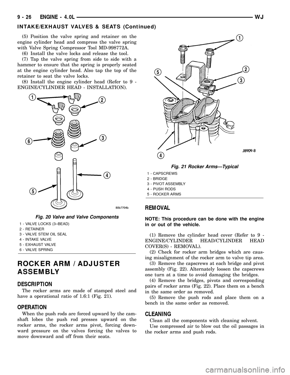
(5) Position the valve spring and retainer on the
engine cylinder head and compress the valve spring
with Valve Spring Compressor Tool MD-998772A.
(6) Install the valve locks and release the tool.
(7) Tap the valve spring from side to side with a
hammer to ensure that the spring is properly seated
at the engine cylinder head. Also tap the top of the
retainer to seat the valve locks.
(8) Install the engine cylinder head (Refer to 9 -
ENGINE/CYLINDER HEAD - INSTALLATION).
ROCKER ARM / ADJUSTER
ASSEMBLY
DESCRIPTION
The rocker arms are made of stamped steel and
have a operational ratio of 1.6:1 (Fig. 21).
OPERATION
When the push rods are forced upward by the cam-
shaft lobes the push rod presses upward on the
rocker arms, the rocker arms pivot, forcing down-
ward pressure on the valves forcing the valves to
move downward and off from their seats.
REMOVAL
NOTE: This procedure can be done with the engine
in or out of the vehicle.
(1) Remove the cylinder head cover (Refer to 9 -
ENGINE/CYLINDER HEAD/CYLINDER HEAD
COVER(S) - REMOVAL).
(2) Check for rocker arm bridges which are caus-
ing misalignment of the rocker arm to valve tip area.
(3) Remove the capscrews at each bridge and pivot
assembly (Fig. 22). Alternately loosen the capscrews
one turn at a time to avoid damaging the bridges.
(4) Remove the bridges, pivots and corresponding
pairs of rocker arms (Fig. 22). Place them on a bench
in the same order as removed.
(5) Remove the push rods and place them on a
bench in the same order as removed.
CLEANING
Clean all the components with cleaning solvent.
Use compressed air to blow out the oil passages in
the rocker arms and push rods.
Fig. 20 Valve and Valve Components
1 - VALVE LOCKS (3±BEAD)
2 - RETAINER
3 - VALVE STEM OIL SEAL
4 - INTAKE VALVE
5 - EXHAUST VALVE
6 - VALVE SPRING
Fig. 21 Rocker ArmsÐTypical
1 - CAPSCREWS
2 - BRIDGE
3 - PIVOT ASSEMBLY
4 - PUSH RODS
5 - ROCKER ARMS
9 - 26 ENGINE - 4.0LWJ
INTAKE/EXHAUST VALVES & SEATS (Continued)
Page 1271 of 2199
VALVE SPRINGS
DESCRIPTION
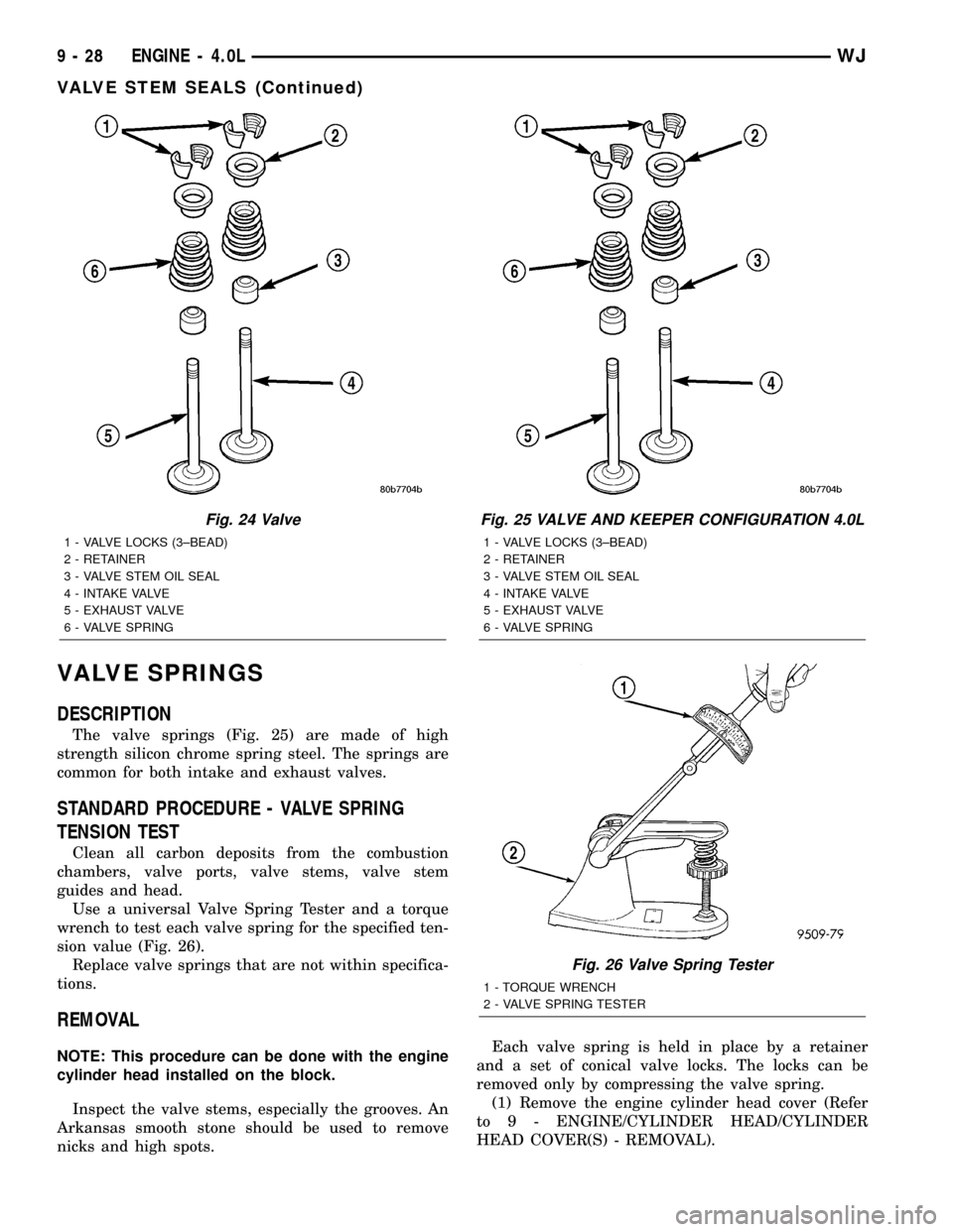
The valve springs (Fig. 25) are made of high
strength silicon chrome spring steel. The springs are
common for both intake and exhaust valves.
STANDARD PROCEDURE - VALVE SPRING
TENSION TEST
Clean all carbon deposits from the combustion
chambers, valve ports, valve stems, valve stem
guides and head.
Use a universal Valve Spring Tester and a torque
wrench to test each valve spring for the specified ten-
sion value (Fig. 26).
Replace valve springs that are not within specifica-
tions.
REMOVAL
NOTE: This procedure can be done with the engine
cylinder head installed on the block.
Inspect the valve stems, especially the grooves. An
Arkansas smooth stone should be used to remove
nicks and high spots.Each valve spring is held in place by a retainer
and a set of conical valve locks. The locks can be
removed only by compressing the valve spring.
(1) Remove the engine cylinder head cover (Refer
to 9 - ENGINE/CYLINDER HEAD/CYLINDER
HEAD COVER(S) - REMOVAL).
Fig. 24 Valve
1 - VALVE LOCKS (3±BEAD)
2 - RETAINER
3 - VALVE STEM OIL SEAL
4 - INTAKE VALVE
5 - EXHAUST VALVE
6 - VALVE SPRING
Fig. 25 VALVE AND KEEPER CONFIGURATION 4.0L
1 - VALVE LOCKS (3±BEAD)
2 - RETAINER
3 - VALVE STEM OIL SEAL
4 - INTAKE VALVE
5 - EXHAUST VALVE
6 - VALVE SPRING
Fig. 26 Valve Spring Tester
1 - TORQUE WRENCH
2 - VALVE SPRING TESTER
9 - 28 ENGINE - 4.0LWJ
VALVE STEM SEALS (Continued)
Page 1272 of 2199
(2) Remove cap screws, bridge and pivot assem-
blies and rocker arms (Refer to 9 - ENGINE/CYLIN-
DER HEAD/ROCKER ARM / ADJUSTER ASSY -
REMOVAL) for access to each valve spring to be
removed.
(3) Remove push rods.Retain the push rods,
bridges, pivots and rocker arms in the same
order and position as removed.
(4) Inspect the springs and retainer for cracks and
possible signs of weakening.
(5) Remove the spark plug(s) adjacent to the cylin-
der(s) below the valve springs to be removed.
(6) Connect an air hose to the adapter and apply
air pressure slowly. Maintain at least 621 kPa (90
psi) of air pressure in the cylinder to hold the valves
against their seats. For vehicles equipped with an air
conditioner, use a flexible air adaptor when servicing
the No.1 cylinder.
(7) Tap the retainer or tip with a rawhide hammer
to loosen the lock from the retainer. Use Valve Spring
Compressor Tool MD-998772A to compress the spring
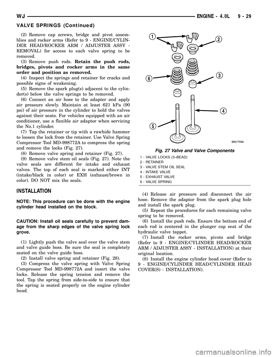
and remove the locks (Fig. 27).
(8) Remove valve spring and retainer (Fig. 27).
(9) Remove valve stem oil seals (Fig. 27). Note the
valve seals are different for intake and exhaust
valves. The top of each seal is marked either INT
(intake/black in color) or EXH (exhaust/brown in
color). DO NOT mix the seals.
INSTALLATION
NOTE: This procedure can be done with the engine
cylinder head installed on the block.
CAUTION: Install oil seals carefully to prevent dam-
age from the sharp edges of the valve spring lock
grove.
(1) Lightly push the valve seal over the valve stem
and valve guide boss. Be sure the seal is completely
seated on the valve guide boss.
(2) Install valve spring and retainer (Fig. 28).
(3) Compress the valve spring with Valve Spring
Compressor Tool MD-998772A and insert the valve
locks. Release the spring tension and remove the
tool. Tap the spring from side-to-side to ensure that
the spring is seated properly on the engine cylinder
head.(4) Release air pressure and disconnect the air
hose. Remove the adaptor from the spark plug hole
and install the spark plug.
(5) Repeat the procedures for each remaining valve
spring to be removed.
(6) Install the push rods. Ensure the bottom end of
each rod is centered in the plunger cap seat of the
hydraulic valve tappet.
(7) Install the rocker arms, pivots and bridge
(Refer to 9 - ENGINE/CYLINDER HEAD/ROCKER
ARM / ADJUSTER ASSY - INSTALLATION) at their
original location.
(8) Install the engine cylinder head cover (Refer to
9 - ENGINE/CYLINDER HEAD/CYLINDER HEAD
COVER(S) - INSTALLATION).
Fig. 27 Valve and Valve Components
1 - VALVE LOCKS (3±BEAD)
2 - RETAINER
3 - VALVE STEM OIL SEAL
4 - INTAKE VALVE
5 - EXHAUST VALVE
6 - VALVE SPRING
WJENGINE - 4.0L 9 - 29
VALVE SPRINGS (Continued)
Page 1273 of 2199
ENGINE BLOCK
CLEANING
Thoroughly clean the oil pan and engine block gas-
ket surfaces.
Use compressed air to clean out:
²The galley at the oil filter adaptor hole.
²The front and rear oil galley holes.
²The feed holes for the crankshaft main bearings.
Once the block has been completely cleaned, apply
Loctite PST pipe sealant with Teflon 592 to the
threads of the front and rear oil galley plugs. Tighten
the plugs to 34 N´m (25 ft. lbs.) torque.
INSPECTION
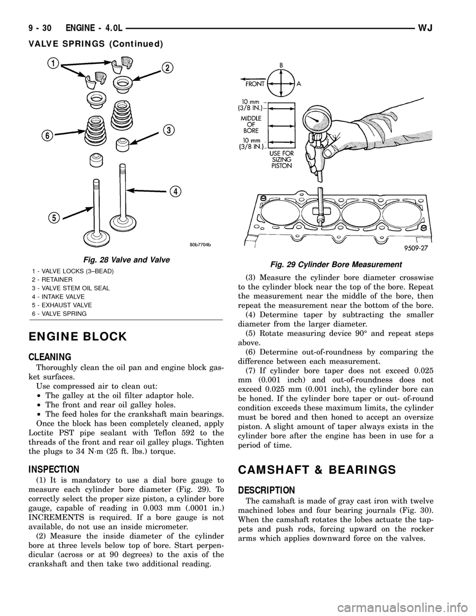
(1) It is mandatory to use a dial bore gauge to
measure each cylinder bore diameter (Fig. 29). To
correctly select the proper size piston, a cylinder bore
gauge, capable of reading in 0.003 mm (.0001 in.)
INCREMENTS is required. If a bore gauge is not
available, do not use an inside micrometer.
(2) Measure the inside diameter of the cylinder
bore at three levels below top of bore. Start perpen-
dicular (across or at 90 degrees) to the axis of the
crankshaft and then take two additional reading.(3) Measure the cylinder bore diameter crosswise
to the cylinder block near the top of the bore. Repeat
the measurement near the middle of the bore, then
repeat the measurement near the bottom of the bore.
(4) Determine taper by subtracting the smaller
diameter from the larger diameter.
(5) Rotate measuring device 90É and repeat steps
above.
(6) Determine out-of-roundness by comparing the
difference between each measurement.
(7) If cylinder bore taper does not exceed 0.025
mm (0.001 inch) and out-of-roundness does not
exceed 0.025 mm (0.001 inch), the cylinder bore can
be honed. If the cylinder bore taper or out- of-round
condition exceeds these maximum limits, the cylinder
must be bored and then honed to accept an oversize
piston. A slight amount of taper always exists in the
cylinder bore after the engine has been in use for a
period of time.
CAMSHAFT & BEARINGS
DESCRIPTION
The camshaft is made of gray cast iron with twelve
machined lobes and four bearing journals (Fig. 30).
When the camshaft rotates the lobes actuate the tap-
pets and push rods, forcing upward on the rocker
arms which applies downward force on the valves.
Fig. 28 Valve and Valve
1 - VALVE LOCKS (3±BEAD)
2 - RETAINER
3 - VALVE STEM OIL SEAL
4 - INTAKE VALVE
5 - EXHAUST VALVE
6 - VALVE SPRINGFig. 29 Cylinder Bore Measurement
9 - 30 ENGINE - 4.0LWJ
VALVE SPRINGS (Continued)
Page 1300 of 2199

INSTALLATION
A gear-type oil pump is mounted at the underside
of the cylinder block opposite the No.4 main bearing.
(1) Install the oil pump on the cylinder block using
a replacement gasket. Tighten the bolts to 23 N´m
(17 ft. lbs.) torque.
(2) Install the oil pan (Refer to 9 - ENGINE/LU-
BRICATION/OIL PAN - INSTALLATION).
(3) Fill the oil pan with oil to the specified level.
INTAKE MANIFOLD
DESCRIPTION
The intake manifold (Fig. 83) is made of cast alu-
minum and uses eleven bolts to mount to the cylin-
der head. This mounting style improves sealing and
reduces the chance of leaks.
DIAGNOSIS AND TESTING - INTAKE
MANIFOLD LEAKAGE
An intake manifold air leak is characterized by
lower than normal manifold vacuum. Also, one or
more cylinders may not be functioning.
WARNING: USE EXTREME CAUTION WHEN THE
ENGINE IS OPERATING. DO NOT STAND IN A
DIRECT LINE WITH THE FAN. DO NOT PUT YOUR
HANDS NEAR THE PULLEYS, BELTS OR THE FAN.
DO NOT WEAR LOOSE CLOTHING.
(1) Start the engine.
(2) Spray a small stream of water at the suspected
leak area.
(3) If a change in RPM is observed the area of the
suspected leak has been found.
(4) Repair as required.
REMOVAL
NOTE: THE ENGINE INTAKE AND EXHAUST MANI-
FOLD MUST BE REMOVED AND INSTALLED
TOGETHER. THE MANIFOLDS USE A COMMON
GASKET AT THE CYLINDER HEAD.
(1) Disconnect the battery negative cable.
(2) Remove air cleaner inlet hose from the resona-
tor assembly.
(3) Remove the air cleaner assembly.
(4) Remove the throttle cable, vehicle speed control
cable (if equipped) and the transmission line pres-
sure cable (Refer to 21 - TRANSMISSION/TRANS-
AXLE/AUTOMATIC - AW4/THROTTLE VALVE
CABLE - REMOVAL).
(5) Disconnect the following electrical connections
and secure their harness out of the way:
²Throttle Position Sensor
²Idle Air Control Motor
²Coolant Temperature Sensor (at thermostat
housing)
²Intake Air Temperature Sensor
²Oxygen Sensor
²Crank Position Sensor
²Six (6) Fuel Injector Connectors
²Manifold Absolute Pressure (MAP) Sensor.
(6) Disconnect HVAC, and Brake Booster vacuum
supply hoses at the intake manifold.
(7) Perform the fuel pressure release procedure.
(Refer to 14 - FUEL SYSTEM/FUEL DELIVERY -
STANDARD PROCEDURE).
(8) Disconnect and remove the fuel system supply
line from the fuel rail assembly.
(9) Remove the accessory drive belt (Refer to 7 -
COOLING/ACCESSORY DRIVE/DRIVE BELTS -
REMOVAL).
(10) Remove the power steering pump from the
intake manifold and set aside.
(11) Raise the vehicle.
(12) Disconnect the exhaust pipes from the engine
exhaust manifolds.
(13) Lower the vehicle.
(14) Remove the intake manifold and exhaust
manifold bolts and manifolds (Fig. 84).
INSTALLATION
If the manifold is being replaced, ensure all the fit-
ting, etc. are transferred to the replacement mani-
fold.
(1) Install a new engine exhaust/intake manifold
gasket over the alignment dowels on the cylinder
head.
(2) Position the engine exhaust manifolds to the
cylinder head. Install fastener Number 3 and finger
tighten at this time (Fig. 84).
Fig. 83 Intake Manifold 4.0L Engine
WJENGINE - 4.0L 9 - 57
OIL PUMP (Continued)
Page 1301 of 2199
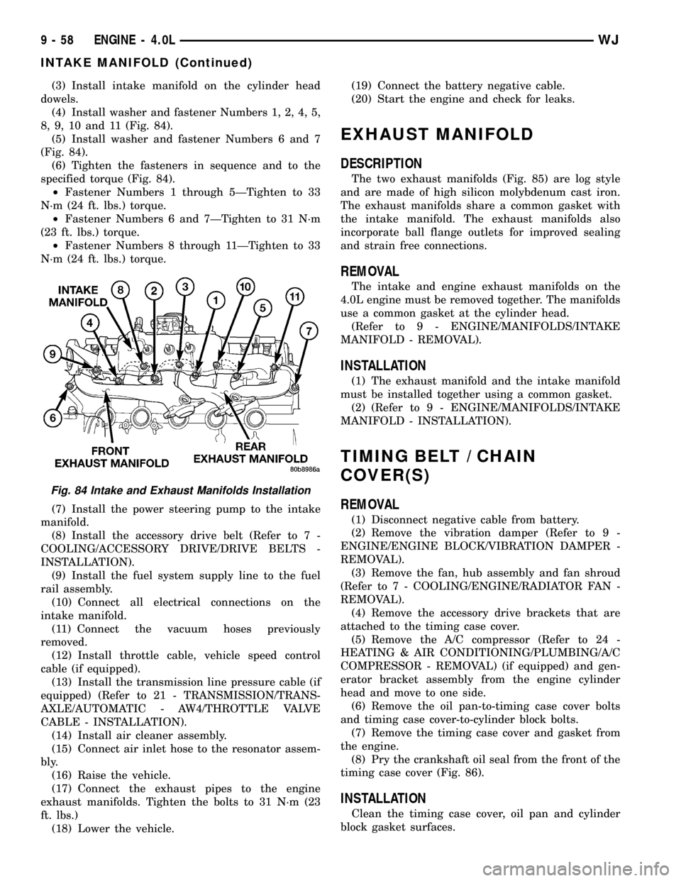
(3) Install intake manifold on the cylinder head
dowels.
(4) Install washer and fastener Numbers 1, 2, 4, 5,
8, 9, 10 and 11 (Fig. 84).
(5) Install washer and fastener Numbers 6 and 7
(Fig. 84).
(6) Tighten the fasteners in sequence and to the
specified torque (Fig. 84).
²Fastener Numbers 1 through 5ÐTighten to 33
N´m (24 ft. lbs.) torque.
²Fastener Numbers 6 and 7ÐTighten to 31 N´m
(23 ft. lbs.) torque.
²Fastener Numbers 8 through 11ÐTighten to 33
N´m (24 ft. lbs.) torque.
(7) Install the power steering pump to the intake
manifold.
(8) Install the accessory drive belt (Refer to 7 -
COOLING/ACCESSORY DRIVE/DRIVE BELTS -
INSTALLATION).
(9) Install the fuel system supply line to the fuel
rail assembly.
(10) Connect all electrical connections on the
intake manifold.
(11) Connect the vacuum hoses previously
removed.
(12) Install throttle cable, vehicle speed control
cable (if equipped).
(13) Install the transmission line pressure cable (if
equipped) (Refer to 21 - TRANSMISSION/TRANS-
AXLE/AUTOMATIC - AW4/THROTTLE VALVE
CABLE - INSTALLATION).
(14) Install air cleaner assembly.
(15) Connect air inlet hose to the resonator assem-
bly.
(16) Raise the vehicle.
(17) Connect the exhaust pipes to the engine
exhaust manifolds. Tighten the bolts to 31 N´m (23
ft. lbs.)
(18) Lower the vehicle.(19) Connect the battery negative cable.
(20) Start the engine and check for leaks.
EXHAUST MANIFOLD
DESCRIPTION
The two exhaust manifolds (Fig. 85) are log style
and are made of high silicon molybdenum cast iron.
The exhaust manifolds share a common gasket with
the intake manifold. The exhaust manifolds also
incorporate ball flange outlets for improved sealing
and strain free connections.
REMOVAL
The intake and engine exhaust manifolds on the
4.0L engine must be removed together. The manifolds
use a common gasket at the cylinder head.
(Refer to 9 - ENGINE/MANIFOLDS/INTAKE
MANIFOLD - REMOVAL).
INSTALLATION
(1) The exhaust manifold and the intake manifold
must be installed together using a common gasket.
(2) (Refer to 9 - ENGINE/MANIFOLDS/INTAKE
MANIFOLD - INSTALLATION).
TIMING BELT / CHAIN
COVER(S)
REMOVAL
(1) Disconnect negative cable from battery.
(2) Remove the vibration damper (Refer to 9 -
ENGINE/ENGINE BLOCK/VIBRATION DAMPER -
REMOVAL).
(3) Remove the fan, hub assembly and fan shroud
(Refer to 7 - COOLING/ENGINE/RADIATOR FAN -
REMOVAL).
(4) Remove the accessory drive brackets that are
attached to the timing case cover.
(5) Remove the A/C compressor (Refer to 24 -
HEATING & AIR CONDITIONING/PLUMBING/A/C
COMPRESSOR - REMOVAL) (if equipped) and gen-
erator bracket assembly from the engine cylinder
head and move to one side.
(6) Remove the oil pan-to-timing case cover bolts
and timing case cover-to-cylinder block bolts.
(7) Remove the timing case cover and gasket from
the engine.
(8) Pry the crankshaft oil seal from the front of the
timing case cover (Fig. 86).
INSTALLATION
Clean the timing case cover, oil pan and cylinder
block gasket surfaces.
Fig. 84 Intake and Exhaust Manifolds Installation
9 - 58 ENGINE - 4.0LWJ
INTAKE MANIFOLD (Continued)
Page 1304 of 2199
ENGINE - 4.7L
TABLE OF CONTENTS
page page
ENGINE - 4.7L
DESCRIPTIONÐ4.7L ENGINE.............63
DIAGNOSIS AND TESTING
DIAGNOSIS AND TESTING - ENGINE
DIAGNOSIS - INTRODUCTION...........64
DIAGNOSIS AND TESTING - ENGINE
DIAGNOSIS - PERFORMANCE...........65
DIAGNOSIS AND TESTING - ENGINE
DIAGNOSIS - MECHANICAL.............66
DIAGNOSIS AND TESTING - ENGINE
DIAGNOSIS - LUBRICATION.............67
DIAGNOSIS AND TESTING - CYLINDER
COMPRESSION PRESSURE.............68
DIAGNOSIS AND TESTING - CYLINDER
COMBUSTION PRESSURE LEAKAGE......69
STANDARD PROCEDURE
STANDARD PROCEDURE - REPAIR
DAMAGED OR WORN THREADS.........70
STANDARD PROCEDURE - FORM-IN-
PLACE GASKETS AND SEALERS.........70
STANDARD PROCEDURE - ENGINE
GASKET SURFACE PREPARATION........70
STANDARD PROCEDURE - ENGINE CORE
AND OIL GALLERY PLUGS..............71
REMOVAL.............................71
INSTALLATION.........................73
SPECIFICATIONS
4.7L ENGINE.........................74
SPECIFICATIONS - 4.7L H.O. ENGINE.....77
TORQUE............................79
SPECIAL TOOLS
4.7L ENGINE.........................80
AIR CLEANER ELEMENT
REMOVAL - 4.7L........................83
INSTALLATION - 4.7L....................83
AIR CLEANER HOUSING
REMOVAL - 4.7L........................84
INSTALLATION - 4.7L....................84
CYLINDER HEAD - LEFT
DESCRIPTION
DESCRIPTION - CYLINDER HEAD........84
DESCRIPTION - VALVE GUIDES..........84
DIAGNOSIS AND TESTING
DIAGNOSIS AND TESTING - HYDRAULIC
LASH ADJUSTER.....................84
DIAGNOSIS AND TESTINGÐCYLINDER
HEAD GASKET.......................85
REMOVAL.............................85
CLEANING............................86
INSPECTION..........................87INSTALLATION.........................87
CAMSHAFT(S) - LEFT
DESCRIPTION.........................88
REMOVAL.............................89
INSTALLATION.........................90
CYLINDER HEAD COVER(S) - LEFT
DESCRIPTION.........................93
REMOVAL - LEFT SIDE..................93
CLEANING............................93
INSTALLATIONÐLEFT SIDE...............93
INTAKE/EXHAUST VALVES & SEATS
DESCRIPTION.........................94
STANDARD PROCEDUREÐREFACING......94
REMOVAL.............................94
INSTALLATION.........................95
ROCKER ARM / ADJUSTER ASSEMBLY
DESCRIPTION.........................96
REMOVAL.............................96
INSTALLATION.........................96
VALVE SPRINGS
DESCRIPTION.........................97
VALVE STEM SEALS
DESCRIPTION.........................97
CYLINDER HEAD - RIGHT
DESCRIPTION
DESCRIPTION - CYLINDER HEAD........97
DESCRIPTION - VALVE GUIDES..........97
DIAGNOSIS AND TESTING
DIAGNOSIS AND TESTINGÐCYLINDER
HEAD GASKET.......................97
DIAGNOSIS AND TESTING - HYDRAULIC
LASH ADJUSTER.....................98
REMOVAL.............................98
CLEANING............................99
INSPECTION..........................99
INSTALLATION.........................99
CAMSHAFT(S) - RIGHT
DESCRIPTION........................100
REMOVAL............................100
INSTALLATION........................102
CYLINDER HEAD COVER(S) - RIGHT
DESCRIPTION........................104
REMOVAL - RIGHT SIDE................104
CLEANING...........................104
INSTALLATION - RIGHT SIDE.............104
INTAKE/EXHAUST VALVES & SEATS
DESCRIPTION........................104
STANDARD PROCEDUREÐREFACING.....105
REMOVAL............................105
INSTALLATION........................106
WJENGINE - 4.7L 9 - 61
Page 1305 of 2199
ROCKER ARM / ADJUSTER ASSEMBLY
DESCRIPTION........................107
REMOVAL............................107
INSTALLATION........................107
VALVE SPRINGS
DESCRIPTION........................108
VALVE STEM SEALS
DESCRIPTION........................108
ENGINE BLOCK
DESCRIPTION........................108
STANDARD PROCEDUREÐCYLINDER BORE
HONING...........................108
CLEANING...........................109
INSPECTION.........................109
CONNECTING ROD BEARINGS
STANDARD PROCEDURE - CONNECTING
ROD BEARING FITTING...............109
CRANKSHAFT
DESCRIPTION........................111
STANDARD PROCEDURE - MEASURING
CRANKSHAFT END PLAY..............111
REMOVAL............................112
INSPECTION..........................112
INSTALLATION........................112
CRANKSHAFT MAIN BEARINGS
STANDARD PROCEDUREÐCRANKSHAFT
MAIN BEARING - FITTING..............114
INSPECTION..........................115
CRANKSHAFT OIL SEAL - FRONT
REMOVAL............................115
INSTALLATION........................116
CRANKSHAFT OIL SEAL - REAR
REMOVAL............................117
INSTALLATION........................117
FLEX PLATE
REMOVAL............................118
INSTALLATION........................118
PISTON & CONNECTING ROD
DESCRIPTION........................118
STANDARD PROCEDUREÐPISTON FITTING . 118
REMOVAL............................118
CLEANING...........................119
INSPECTION..........................119
INSTALLATION........................120
PISTON RINGS
STANDARD PROCEDURE - PISTON RING
FITTING............................121
VIBRATION DAMPER
REMOVAL............................122
INSTALLATION........................123
STRUCTURAL COVER
DESCRIPTION........................124
OPERATION..........................124
REMOVAL............................124
INSTALLATION........................124
FRONT MOUNT
REMOVAL............................124INSTALLATION........................125
REAR MOUNT
REMOVAL............................125
INSTALLATION........................126
LUBRICATION
DESCRIPTION........................126
OPERATION..........................126
DIAGNOSIS AND TESTING
DIAGNOSIS AND TESTINGÐENGINE OIL
PRESSURE.........................128
DIAGNOSIS AND TESTINGÐREAR SEAL
AREA LEAKS........................128
DIAGNOSIS AND TESTINGÐENGINE OIL
LEAK..............................129
OIL
STANDARD PROCEDURE - ENGINE OIL....130
OIL FILTER
REMOVAL............................131
INSTALLATION........................132
OIL PAN
DESCRIPTION........................132
REMOVAL............................132
CLEANING...........................132
INSPECTION.........................132
INSTALLATION........................132
OIL PRESSURE SENSOR/SWITCH
DESCRIPTION........................133
OPERATION..........................133
REMOVAL............................133
INSTALLATION........................133
OIL PUMP
REMOVAL............................134
DISASSEMBLY........................134
CLEANING...........................134
INSPECTION.........................134
ASSEMBLY...........................135
INSTALLATION........................135
INTAKE MANIFOLD
DESCRIPTION........................136
DIAGNOSIS AND TESTINGÐINTAKE
MANIFOLD LEAKAGE.................136
REMOVAL............................136
CLEANING...........................137
INSPECTION.........................137
INSTALLATION........................137
EXHAUST MANIFOLD - LEFT
DESCRIPTION........................138
REMOVAL............................138
CLEANING...........................138
INSPECTION.........................138
INSTALLATION........................138
EXHAUST MANIFOLD - RIGHT
DESCRIPTION........................139
REMOVAL............................139
CLEANING...........................140
INSPECTION.........................141
INSTALLATION........................141
9 - 62 ENGINE - 4.7LWJ